
Related Manuals for GEA VARIVENT A


Summary of Contents for GEA VARIVENT A
- Page 1 Translation of the Original Operating Instructions ® VARIVENT Control Valve A Edition 2016-06-07 English...
- Page 2 EU Machinery Directive. This document is protected by copy- right. All rights reserved. The document may not, in whole or in part, be copied, reproduced, translated or reduced to an electronic medium of machine-readable form without the express permission of GEA Tuchenhagen GmbH. ® The designation VARIVENT is a protected trademark of GEA Tuchenhagen GmbH.
-
Page 3: Table Of Contents
Table of Contents Table of Contents Notes for the Reader ............................6 Binding Character of These Operating Instructions ..................6 Notes on the Illustrations ..........................6 Symbols and Highlighting ..........................7 Abbreviations and Terms ..........................8 Safety ................................10 Safety Note ..............................10 Operator's Duties ............................ - Page 4 Table of Contents Control Valve with Welding Ends ........................27 Pneumatic Connections ..........................29 Electrical Connections............................. 30 Commissioning..............................31 • Checks Prior to Commissioning ........................31 • Testing the Valve Function Without Product ....................31 • Valve Stroke ..............................32 •...
- Page 5 Table of Contents Spare Parts Lists – Control Valve Housings....................57 Spare Parts List – Control Valve Actuator A....................72...
-
Page 6: Notes For The Reader
Notes for the Reader Notes on the Illustrations Notes for the Reader The present Operating Instructions are part of the user information for the valve. The Operating Instructions contain all the information you need to transport, install, commis- sion, operate and carry out maintenance for the valve. Binding Character of These Operating Instructions These Operating Instructions contain the manufacturer's instructions to the operator of the valve and to all persons who work on or use the valve regarding the procedures to... -
Page 7: Symbols And Highlighting
Notes for the Reader Symbols and Highlighting Symbols and Highlighting In these Operating Instructions, important information is highlighted by symbols or special formatting. The following examples illustrate the most important types of high- lighting. DANGER Warning: Fatal Injuries. Failure to observe the warning can result in serious damage to health, or even death. ... -
Page 8: Abbreviations And Terms
Notes for the Reader Abbreviations and Terms IMPORTANT NOTE Warning: Damage to Property. Failure to observe the warning can result in serious damage to the valve or in the vicinity of the valve. The arrow identifies a precautionary measure you have to take to avoid the hazard. Carry out the following steps: = Start of a set of instructions. - Page 9 Notes for the Reader Abbreviations and Terms Abbreviation Explanation HNBR Material designation Short designation according to DIN/ISO 1629: Hydrogenated Acrylonitrile Butadiene Rubber Protection class International standard issued by the International Organization for Standardi- zation Unit of measurement of weight [kilogram] Unit of measurement of force [kilonewton] value Flow coefficient [m³/s]...
-
Page 10: Safety
Safety Operator's Duties Safety Safety Note The valve is operationally reliable. It was built according to state-of-the-art standards. Nevertheless, the valve can pose dangers, especially if • the valve is not used in accordance with its intended use, • the valve is not used correctly, •... -
Page 11: Qualification Of Staff
Safety Qualification of Staff Qualification of Staff This section contains information about the qualifications that staff working on the valve must have. Operating and maintenance staff must • have the necessary qualification to carry out their tasks, • be instructed with regard to possible dangers, •... -
Page 12: Supplementary Regulations
Safety Supplementary Regulations User groups (Cont.) Staff Qualifications Maintenance staff Adequate instruction as well as sound knowledge of the design and function of the valve. Sound knowledge in the following areas: • Mechanical equipment • Electrical equipment • Pneumatic system Authorization with regard to safety engineering standards to carry out the following tasks: •... -
Page 13: Instructions For The Safe Operation
Safety Instructions for the Safe Operation Instructions for the Safe Operation Dangerous situations during the operation can be avoided by safety-conscious and proactive behaviour of the staff. General Principles To ensure the safe operation of the valve the following principles apply: •... -
Page 14: Commissioning/Setup Mode
Safety Instructions for the Safe Operation Commissioning/Setup Mode For commissioning, the following principles apply: • Take protective measures against dangerous contact voltages in accordance with pertinent regulations. • The valve must be completely assembled and correctly adjusted. All screw connec- tions must be securely tightened. -
Page 15: Shutting Down
Safety Instructions for the Safe Operation Shutting Down For shutting down, the following principles apply: • Switch off the compressed air. • Switch off the valve via the main switch. • Padlock the main switch (if fitted) in the off position to prevent it from being switched back on. -
Page 16: Disassembly
Safety Instructions for the Safe Operation Disassembly For disassembly, the following principles apply: • Only allow qualified staff to disassemble the valve. • Before starting disassembly, the valve must be switched off and secured against being switched back on. Work may only be started once any residual energy has been discharged. -
Page 17: Signage
Safety Signage Signage Dangerous points on the valve are indicated by warning signs, prohibition signs and mandatory signs. The signs and notes on the valve must always be legible. Any illegible signs must be replaced immediately. Signs on the valve Sign Meaning General hazard warning... -
Page 18: Residual Risk
Safety Residual Risk Residual Risk Hazard Areas Please observe the following notes: • In the event of malfunctions, shut down the valve (disconnect from the power and air supply) and secure it against being used. • When the valve is switching, never reach into the valve housing (391), the lantern (9) or into the valve inlet X (on pneumatic actuators). -
Page 19: Residual Dangers
Cover or safeguard any adjacent live parts. Spring tension in the actuator Danger to life caused by compression spring in the actuator. Do not open actuators but return them to GEA Tuchenhagen for proper disposal. Danger of injury Danger presented by moving The operator must exercise caution and prudence. -
Page 20: Declaration Of Conformity
2006/42/EC Applicable harmonized standards: DIN EN ISO 12100 Authorised representative for compilation Authorised representative - CE of the technical documentation documentation GEA Tuchenhagen GmbH At Industriepark 2-10 21514 Büchen Büchen, 16/02/2015 Franz Bürmann i.V. Matthias Südel Managing Director Team Leader Product Development Operating Instructions ·... -
Page 21: Transport And Storage
Transport and Storage Storage Transport and Storage Scope of Supply On receipt of the valve check whether • the details on the type plate correspond to the data in the order and delivery docu- ments, • the equipment is complete and all components are in good order. Transport For transport, the following principles apply: •... -
Page 22: Intended Purpose
The control valves are pressure equipment (without safety function) in the sense of the pressure equipment directive 97/23/EC. They are classified according to Annex II, article 3, section 3. In the event of any deviations, GEA Tuchenhagen GmbH will supply a special Declaration of Conformity. -
Page 23: Improper Operating Conditions
EC Machinery Direc- tive on your own. In general, only original spare parts supplied by GEA Tuchenhagen GmbH should be fitted. This ensures the reliable and economical operation of the valve. -
Page 24: Design And Function
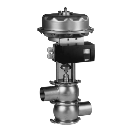
Design and Function Design Design and Function Design Designation Diaphragm actuator Actuator spindle Lantern Coupling Valve housing Valve insert with control cone The lantern (3) forms the connection between the actuator housing and the upper valve housing (5). It holds the pneumatic positioner. The coupling (4) connects the valve insert (6) with the actuator spindle (2). -
Page 25: Function
Design and Function Function Function Spring-to-close actuator (Z) The valve is closed in the non-actuated position. In the standard version, the control valve is supplied with a spring-to-close actuator – spring closed in the non-actuated position –, i.e.: If the input signal at the positioner increases, the control valve opens. Spring-to-open actuator (A) The valve is open in the non-actuated position. -
Page 26: Installation And Commissioning
Installation and Commissioning Notes on Installation GEA Tuchenhagen recommends that the valve should be installed vertically (actuator up, housing bottom). If the control valve is not installed vertically, the stress on the valve stem seals is higher than when installed vertically. Therefore, regularly check the control valve for leakage. -
Page 27: Control Valve With Welding Ends
Installation and Commissioning Control Valve with Welding Ends Control Valve with Welding Ends The valve housing must be dismantled for welding. Requirement: WARNING Spring tension in the valve Danger of injury when releasing the hinged clamps (2, 4) as the released spring preten- sion will suddenly lift the actuator. - Page 28 Installation and Commissioning Control Valve with Welding Ends Assemble the valve and depressurize the actuator. The valve disk is lowered. Done NOTE Welding method: we recommend using the TIG welding method. When assembling the valve always replace the housing O-rings to ensure that the valve is tight.
-
Page 29: Pneumatic Connections
Installation and Commissioning Pneumatic Connections Pneumatic Connections Pneumatic connections Item Explanation Exhaust air outlet with sound absorber at the bottom of the housing Supply air Feedback source Signal pressure on single and double-acting actuators Signal pressure on double-acting actuators The control air pressure may be max. -
Page 30: Electrical Connections
Installation and Commissioning Electrical Connections Electrical Connections DANGER Live parts Electrical shock can result in serious personal injury or death. Only allow properly qualified staff to carry out work on the electrical equipment. Prior to establishing electrical connections check the maximum permissible oper- ating voltage. -
Page 31: Commissioning
Installation and Commissioning Commissioning Commissioning Checks Prior to Commissioning Before starting commissioning observe the following: Mechanical • Check that all visible screws are firmly secured. • Make sure that there are no foreign materials in the system. • Check that all movable parts of the control valve can move freely. •... -
Page 32: Valve Stroke
Installation and Commissioning Commissioning Valve Stroke Valve Stroke Table Actuator type/size Valve stroke (mm) MFI-20 MFI-30 MFIII-30 MFIII-60 Tests During the Product Run Carry out the following steps: Check by visual inspection whether – all valve functions are correct and –... -
Page 33: Cleaning And Passivation
Cleaning and Passivation Cleaning Process Examples Cleaning and Passivation Cleaning All parts in contact with product must be cleaned at regular intervals. Always observe the safety data sheets issued by the cleaning agent manufacturers. Only use cleaning agents which do not cause damage to the seals and the inner parts of the valve. When the pipe is cleaned, the cleaning medium also flows through and cleans the valve hous- ings. -
Page 34: Cleaning Parameters
Cleaning and Passivation Cleaning Process Examples Cleaning Parameters The cleaning effect depends on the following factors: • Temperature • Time • Mechanics • Chemicals • Degree of soiling. These factors can be combined in various ways to achieve an optimal cleaning result. Please define the cleaning parameters yourself in accordance with your product and process and regularly verify the result. -
Page 35: Malfunctions
Malfunctions Malfunctions In the event of malfunctions immediately deactivate the control valve and secure it against inadvertent reactivation. Malfunctions may only be remedied by qualified staff, who must observe the safety instructions. Malfunction Cause Remedy Valve does not work Fault in the control system Check the system configuration No compressed air Check the compressed air supply Compressed air pressure... -
Page 36: Maintenance
Maintenance Inspections Maintenance Inspections Between the maintenance periods, the control valves must be checked for leakage and proper function. Product Contact Seals Carry out the following steps: Regularly check the seals. Done Pneumatic Connections Carry out the following steps: Check the operating pressure at the pressure reducing and filter station. -
Page 37: Maintenance Intervals
Maintenance Prior to Disassembly Maintenance Intervals To ensure the highest operational reliability of the valves, all wearing parts should be replaced at longer intervals. The actual maintenance intervals can only be determined by the user since they depend on the operating conditions, for instance: •... -
Page 38: Disassembly
Maintenance Disassembly Disassembly This section describes disassembly of various components. No solenoid valve must have been activated electrically or manually. Requirement: WARNING Spring tension in the valve Danger of injury when releasing the hinged clamps (2, 4) as the released spring preten- sion will suddenly lift the actuator. -
Page 39: Maintenance
Maintenance Maintenance Maintenance Cleaning the Valve IMPORTANT NOTE Sealing grooves and contact surfaces are precision areas. Damage to the valve can result in a malfunction. Observe the safety information sheets issued by the detergent manufacturers! Only use detergents which are not aggressive towards the materials of the valve, and which are non-abrasive. - Page 40 Maintenance Maintenance Replacing the V-Ring CAUTION The scriber can slip off when the V-ring is removed. Danger of injury! Grip the valve disk in a vice with protected jaws. Unscrew the curved side of the scriber. Carry out the following steps: Put a scriber into the V-ring and take it out.
-
Page 41: Lubricating Seals And Threads
They have the NSF- H1 (USDA H1) registration. PARALIQ GTE 703 can be ordered from GEA Tuchenhagen under material no. 413-064, and Rivolta F.L.G. MD-2 can be ordered under material no. -
Page 42: Assembly
Maintenance Assembly Assembly Carry out the following steps: Assemble control valve and housing in the reverse order of disassembly. Pay attention that the seat rings are positioned correctly: Soft sealing valve disks: inclined seating surface must face the valve disk (A). Metallically sealing valve disks: pointed edge must face the valve disk (B). -
Page 43: Dismantling The Actuator Housing Cover
Maintenance Checking the Function Dismantling the Actuator Housing Cover Depending on the type and size of the control valve, prestressed actuators can be Requirement: fitted with a certain number of over-long screws. If this is not the case, at least 2 opposite short screws must be replaced by long ones. -
Page 44: Valve Stroke
GEA Tuchenhagen accepts unopened actuators and arranges for proper disposal free of charge. Carry out the following steps: Remove the actuator, see “Disassembly“ (page 38). Safely pack the actuator and send it to GEA Tuchenhagen GmbH. Done Operating Instructions · Control Valve A... -
Page 45: Technical Data
Technical Data Type Plate Technical Data Type Plate The type plate clearly identifies the valve. Type plate of Control Valve A The type plate provides the following key data: Key data of the valve Type Control Valve A Serial Serial number Material 1.4404 / cone 1.457/EPDM (FDA) Control air pressure bar/psi... -
Page 46: Technical Data
Technical Data Technical Data Technical Data Technical data: Valve Designation Description Size DN 25 to DN 150 1" to 6" OD 2" to 6" IPS Installation position Any position (if valve and pipe system can drain prop- erly) Material of product contact parts Stainless steel 1.4404 (AISI316L) Product pressure DN 25 to 65 = max. -
Page 47: Resistance Of Sealing Materials
Technical Data Pipe Ends Resistance of Sealing Materials The resistance of sealing materials depends on the type and temperature of the medium conveyed. The exposure time can adversely affect the service life of the seals. The sealing materials comply with the regulations of FDA 21 CFR 177.2600 or FDA 21 CFR 177.1550. -
Page 48: Tools
Technical Data Tools Dimensions for Pipes in DN Metric Outside diameter Wall thickness Inside diam- Outside diameter eter acc. to DIN 11850 Dimensions for Pipes in Inch OD Inch OD Outside diameter Wall thickness Inside diam- Outside diameter eter acc. to BS 4825 Part 1"... -
Page 49: Lubricants
Technical Data Weights List of tools (Cont.) Tools Material no. Hexagon screwdriver a/f 6 408-124 (for hexagon socket screws) Hexagon screwdriver a/f 7 (for hexagon socket screws) Screwdriver, crosstip size 2 406-125 Screwdriver, blade width 3.5 406-103 Open end spanner a/f 8x10 408-032 Open end spanner a/f 13x17 408-036... - Page 50 Technical Data Weights Size Weight* [kg] DN 125 approx. 55.1 DN 150, 6" approx. 61.1 *Weights for housing combination L. Other weights on request. Operating Instructions · Control Valve A Edition 2016-06-07...
-
Page 51: Spare Parts Lists - Control Valves
Spare Parts Lists – Control Valves Control Valve A Spare Parts Lists – Control Valves Control Valve A Control valve with EPDM or FPM valve seat seal Control valve with metallic valve seat seal... - Page 52 Spare Parts Lists – Control Valves Control Valve A Spare Parts List Control Valve A Designation Actuator Coupling element Sealing ring Bearing Sealing disk Bearing disk O-ring V-ring Lantern Control cone Seat ring Cover Hinged clamp Hex screw Hex nut Housing, 1 socket(s) Housing connection A * Sealing set, complete...
-
Page 53: Control Valve A
Spare Parts Lists – Control Valves Control Valve A...W Control Valve A...W Spare parts drawing Control Valve A...W... - Page 54 Spare Parts Lists – Control Valves Control Valve A...W Spare Parts List Control Valve A...W Designation Actuator Coupling element Sealing ring Bearing Sealing disk Bearing disk O-ring V-ring Lantern Control cone Seat ring Cover Housing, 1 socket(s) Hinged clamp Hex screw Hex nut * Sealing set, complete ** Valve insert complete without seals...
-
Page 55: Control Valve A
Spare Parts Lists – Control Valves Control Valve A...X Control Valve A...X Spare parts drawing Control Valve A...X... - Page 56 Spare Parts Lists – Control Valves Control Valve A...X Spare Parts List Control Valve A...X Designation Actuator Coupling element Sealing ring Bearing Sealing disk Bearing disk O-ring V-ring Lantern Control cone Seat ring Cover Housing, 1 socket(s) Hinged clamp Hex screw Hex nut * Sealing set, complete ** Valve insert complete without seals...
- Page 57 For housing combinations AA, AB, AC and AE, an additional bearing is possible for nominal widths DN 125 and 6" IPS. This also applies for housing combinations AW and ABK in the nominal widths from DN 40 and from 2" OD. GEA Mechanical Equipment GEA Tuchenhagen GmbH Am Industriepark 2-10, D-21514 Büchen, Germany...
- Page 58 221-142.12 221-142.13 221-142.13 O-ring EPDM 930-150 930-156 930-372 930-260 930-176 930-178 930-178 930-259 3-stage seat 1.4404 229-168.23 229-168.24 GEA Mechanical Equipment GEA Tuchenhagen GmbH Am Industriepark 2-10, D-21514 Büchen, Germany Telephone +49 4155 49-0, Telefax +49 4155 49-2423 sales.geatuchenhagen@gea.com, http://www.tuchenhagen.com...
- Page 59 932-032 43.0 EPDM 932-021 932-033 50.0 EPDM 932-023 932-034 68.0 EPDM 85.0 EPDM EPDM EPDM EPDM EPDM EPDM GEA Mechanical Equipment GEA Tuchenhagen GmbH Am Industriepark 2-10, D-21514 Büchen, Germany Telephone +49 4155 49-0, Telefax +49 4155 49-2423 sales.geatuchenhagen@gea.com, http://www.tuchenhagen.com...
- Page 60 932-027 932-027 932-038 932-038 932-038 EPDM 932-028 932-039 EPDM 932-059 932-059 932-063 932-063 EPDM 932-045 932-045 932-044 932-044 GEA Mechanical Equipment GEA Tuchenhagen GmbH Am Industriepark 2-10, D-21514 Büchen, Germany Telephone +49 4155 49-0, Telefax +49 4155 49-2423 sales.geatuchenhagen@gea.com, http://www.tuchenhagen.com...
- Page 61 221-107.63 26.0 1.4404 221-107.62 221-107.64 43.0 1.4404 221-107.65 50.0 1.4404 221-107.66 68.0 1.4404 85.0 1.4404 1.4404 1.4404 1.4404 GEA Mechanical Equipment GEA Tuchenhagen GmbH Am Industriepark 2-10, D-21514 Büchen, Germany Telephone +49 4155 49-0, Telefax +49 4155 49-2423 sales.geatuchenhagen@gea.com, http://www.tuchenhagen.com...
- Page 62 221-107.63 26.0 1.4404 221-107.62 221-107.64 43.0 1.4404 221-107.65 50.0 1.4404 221-107.66 68.0 1.4404 85.0 1.4404 1.4404 1.4404 1.4404 GEA Mechanical Equipment GEA Tuchenhagen GmbH Am Industriepark 2-10, D-21514 Büchen, Germany Telephone +49 4155 49-0, Telefax +49 4155 49-2423 sales.geatuchenhagen@gea.com, http://www.tuchenhagen.com...
- Page 63 912-025 912-025 Housing, 1 socket(s) 1.4404 221-101.06 221-101.07 221-101.18 221-101.17 Housing, 2 socket(s) 1.4404 221-102.06 221-102.07 221-102.29 221-102.17 GEA Mechanical Equipment GEA Tuchenhagen GmbH Am Industriepark 2-10, D-21514 Büchen, Germany Telephone +49 4155 49-0, Telefax +49 4155 49-2423 sales.geatuchenhagen@gea.com, http://www.tuchenhagen.com...
- Page 64 221-131.13 50.0 1.4404 68.0 1.4404 221-131.11 221-131.17 85.0 1.4404 221-131.11 1.4404 221-131.23 221-131.29 1.4404 221-131.27 221-131.30 1.4404 221-131.31 GEA Mechanical Equipment GEA Tuchenhagen GmbH Am Industriepark 2-10, D-21514 Büchen, Germany Telephone +49 4155 49-0, Telefax +49 4155 49-2423 sales.geatuchenhagen@gea.com, http://www.tuchenhagen.com...
- Page 65 221-132.65 50.0 1.4404 68.0 1.4404 221-132.64 221-132.66 85.0 1.4404 221-132.64 1.4404 221-132.67 221-132.69 1.4404 221-132.68 221-132.70 1.4404 221-132.71 GEA Mechanical Equipment GEA Tuchenhagen GmbH Am Industriepark 2-10, D-21514 Büchen, Germany Telephone +49 4155 49-0, Telefax +49 4155 49-2423 sales.geatuchenhagen@gea.com, http://www.tuchenhagen.com...
- Page 66 1.4404 221-107.65 221-107.65 221-107.67 50.0 1.4404 221-107.66 68.0 1.4404 221-107.66 221-107.68 85.0 1.4404 221-107.66 1.4404 221-107.69 1.4404 221-107.70 GEA Mechanical Equipment GEA Tuchenhagen GmbH Am Industriepark 2-10, D-21514 Büchen, Germany Telephone +49 4155 49-0, Telefax +49 4155 49-2423 sales.geatuchenhagen@gea.com, http://www.tuchenhagen.com...
- Page 67 SUSTA-PVDF 935-099 935-099 935-102 Bearing, bottom PTFE/carbon 935-001 935-002 935-002 935-003 Bearing, 3A SUSTA-PVDF 935-098 935-099 935-099 935-102 GEA Mechanical Equipment GEA Tuchenhagen GmbH Am Industriepark 2-10, D-21514 Büchen, Germany Telephone +49 4155 49-0, Telefax +49 4155 49-2423 sales.geatuchenhagen@gea.com, http://www.tuchenhagen.com...
- Page 68 221-507.03 221-507.11 221-507.14 Housing, 1 socket(s) 1.4404 221-101.37 221-101.36 221-101.17 Housing, 2 socket(s) 1.4404 221-102.62 221-102.59 221-102.60 221-102.17 GEA Mechanical Equipment GEA Tuchenhagen GmbH Am Industriepark 2-10, D-21514 Büchen, Germany Telephone +49 4155 49-0, Telefax +49 4155 49-2423 sales.geatuchenhagen@gea.com, http://www.tuchenhagen.com...
- Page 69 Hole dia. KVS Value Material 2" IPS 3" IPS 4" IPS 6" IPS 1.4404 221-132.72 1.4404 221-132.73 1.4404 221-132.74 GEA Mechanical Equipment GEA Tuchenhagen GmbH Am Industriepark 2-10, D-21514 Büchen, Germany Telephone +49 4155 49-0, Telefax +49 4155 49-2423 sales.geatuchenhagen@gea.com, http://www.tuchenhagen.com...
- Page 70 Sterile lock HSP cpl., 221-601.19 221-601.09 221-601.10 221-601.11 221-601.12 Sterile lock HSP cpl., 221-601.07 221-601.09 221-601.10 221-601.11 221-601.12 bottom GEA Mechanical Equipment GEA Tuchenhagen GmbH Am Industriepark 2-10, D-21514 Büchen, Germany Telephone +49 4155 49-0, Telefax +49 4155 49-2423 sales.geatuchenhagen@gea.com, http://www.tuchenhagen.com...
- Page 71 EPDM 930-165 * The O-ring (Item 158) is not included in the sterile lock HSP cpl. and must be ordered separately. GEA Mechanical Equipment GEA Tuchenhagen GmbH Am Industriepark 2-10, D-21514 Büchen, Germany Telephone +49 4155 49-0, Telefax +49 4155 49-2423...
- Page 72 Spare Parts List – Control Valve Actuator A Spare Parts List – Control Valve Actuator A Spare Parts List Actuator A Designation Designation Spindle Washer Sealing ring Hex nut Bush Seal Plain bearing Threaded sleeve Operating Instructions · Control Valve A Edition 2016-06-07...
- Page 73 Spare Parts List – Control Valve Actuator A Spare Parts List Actuator A (Cont.) Designation Designation O-ring O-ring Reversing sleeve Diaphragm cover O-ring Diaphragm disk Diaphragm cover Hex screw Diaphragm disk Diaphragm Lantern Pressure spring Seal Spring cover Locking screw Seal Threaded sleeve Protection cap...
- Page 74 We live our values. Excellence Passion Integrity Responsibility GEA-versity GEA Group is a global engineering company with multi-billion euro sales and operations in more than 50 countries. Founded in 1881, the company is one of the largest providers of innovative equipment and ®...
Need help?
Do you have a question about the VARIVENT A and is the answer not in the manual?
Questions and answers