
Subscribe to Our Youtube Channel
Related Manuals for GEA VARIVENT N


Summary of Contents for GEA VARIVENT N
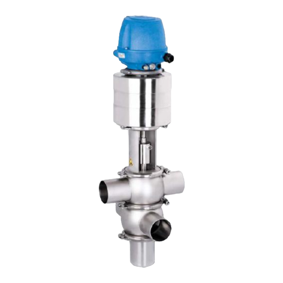
- Page 1 Hygienic valves ® GEA VARIVENT Shut-off valve type N and U, U_R, N_V and U_V Operating instruction (Translation from the original language) 430BAL008302EN_10...
- Page 2 EU Machinery Directive. This document is protected by copyright. All rights reserved. The document may not, in whole or in part, be copied, reproduced, translated or reduced to an electronic medium of machine-readable form without the express permission of GEA Tuchenhagen GmbH. LEGAL NOTICE Wordmarks ®...
-
Page 3: Table Of Contents
TABLE OF CONTENTS General Information Information on the Document 1.1.1 Binding Character of These Operating Instructions 1.1.2 Notes on the Illustrations 1.1.3 Symbols and Highlighting Manufacturer address Contact EU Declaration of Conformity in accordance with the EC Machinery Directive 2006/42/EC Safety Intended use 2.1.1... - Page 4 Cleaning 9.1.1 Cleaning Process Examples 9.1.2 Cleaning results Passivation Maintenance 10.1 Safety instructions 10.2 Inspections 10.2.1 Product contact seals 10.2.2 Pneumatic connections 10.2.3 Electrical connections 10.3 Maintenance intervals 10.4 Prior to disassembly 10.5 Disassembling Valve N 10.5.1 Detaching the Clamp Connection (43.1) 10.5.2 Removing the Control Top 10.5.3...
-
Page 5: General Information
General Information Information on the Document General Information Information on the Document The present Operating Instructions are part of the user information for the product. The Operating Instructions contain all the information you need to transport, install, commission, operate and carry out maintenance for the product. 1.1.1 Binding Character of These Operating Instructions These Operating Instructions contain the manufacturer's instructions to the... -
Page 6: Manufacturer Address
Second step in a sequence of operations. ® Result of the previous operation. ® The operation is complete, the goal has been achieved. Hint! Further useful information. Manufacturer address GEA Tuchenhagen GmbH Am Industriepark 2-10 21514 Büchen Contact Tel.:+49 4155 49-0 Fax:+49 4155 49-2035 flowcomponents@gea.com www.gea.com 430BAL008302EN_10 16.03.2023... -
Page 7: Eu Declaration Of Conformity In Accordance With The Ec Machinery Directive 2006/42/Ec
EU Declaration of Conformity in accordance with the EC Machinery Directive 2006/42/EC EU Declaration of Conformity in accordance with the EC Machinery Directive 2006/42/EC Manufacturer: GEA Tuchenhagen GmbH Am Industriepark 2-10 21514 Büchen We hereby declare that the machine named below... -
Page 8: Safety
Pressure Equipment Directive which specifies sound engineering practice. Nominal diameters ≥ IPS 4“; DN 125 valid for the fluid group II. In the event of any deviations, GEA Tuchenhagen GmbH will supply a specific Declaration of Conformity. 2.1.3... -
Page 9: Operator's Duty Of Care
Safety Operator’s Duty of Care The operation of the component is not permitted if: • Persons or objects are in the danger zone. • Safety devices are not working or were removed. • Malfunctions have been detected on the component. •... -
Page 10: Subsequent Changes
EC Machinery Directive on your own. In general, only original spare parts supplied by GEA Tuchenhagen GmbH should be fitted. This ensures that the component is always operating properly and efficiently. -
Page 11: Electrical Equipment
Safety Supplementary Regulations • Substances harmful to the environment must be collected and stored in suitable containers. Clearly mark the containers. • Dispose of lubricants as hazardous waste. 2.4.3 Electrical Equipment For all work on electrical equipment, the following principles apply: •... -
Page 12: Safety Equipment
Safety Safety equipment • Personal suitability for the respective task. • Sufficient professional qualification for the respective task. • Received instruction about the functionality of the component. • Received instruction about operating sequences on the component. • Familiar with the safety devices and their function. •... -
Page 13: Residual Dangers
Earthing and short-circuiting. Cover or safeguard any adjacent live parts. Spring tension in the actuator Danger to life caused by compression spring in the actuator. Do not open the actuator but return it to GEA Tuchenhagen for proper disposal. 430BAL008302EN_10 16.03.2023... -
Page 14: Danger Zones
Safety Danger zones Residual dangers on the valve and measures Danger Cause Measure Danger of injury Danger presented by moving or The operator must exercise caution and prudence. sharp-edged parts For all work: • Wear suitable work clothing. • Never operate the machine if the cover panels are not correctly fitted. - Page 15 Safety detaching the clamp connection (43.1) by supplying the actuator (A) with compressed air. • Before starting any service, maintenance or repair work, disconnect the valve from the power supply and secure it against inadvertently being switched back on again. •...
-
Page 16: Description
Description Design Description Design Fig.5 Design Designation Actuator T.VIS control top Sealing ring Bearing Sealing disk Bearing disk Lantern Valve disk Air connection 430BAL008302EN_10 16.03.2023... - Page 17 Description Design Design Designation Electrical connection Valve housing 430BAL008302EN_10 16.03.2023...
-
Page 18: Functional Description
Description Functional description Functional description 3.2.1 Valve N Closing Direction Closing direction: from top to bottom Standard: spring-to-close Fig.6: Distinguishing Feature of Spring-To-Close Actuator (Z) The valve is closed in the non-actuated position. Identification: – Green steady light (1): valve in non-actuated position –... - Page 19 Description Closing direction: from the bottom to the top Standard: spring-to-close Marking, type U: Ring groove (a) on the width across flats of the valve disk rod. Fig.8: Distinguishing Feature of Spring-To-Close Actuator (Z) The valve is closed in the non-actuated position. Identification: –...
-
Page 20: Transport And Storage
Transport and storage Storage conditions Transport and storage Storage conditions The valves, valve inserts or spare parts should be stored in a dry place, free of vibrations and dust, and protected from light. To avoid damage, leave the components in their original packaging if possible. If, during transport or storage, the valve is going to be exposed to temperatures ≤... -
Page 21: Scope Of Supply
Transport and storage • Only use approved, fully functional load lifting devices and lifting accessories which are suitable for the intended purpose. Observe the maximum load- bearing capacities. • Secure the valve against slipping. Take the weight of the valve into account and the position of the point of gravity. -
Page 22: Technical Data
Technical data Type plate Technical data Type plate The type plate clearly identifies the valve. GEA Tuchenhagen GmbH Am Industriepark 2-10, 21514 Büchen, Germany Type Serial Mat. Air bar/psi min. max. PSI bar/psi The type plate provides the following key data:... - Page 23 Technical data Technical data Technical data: Ambient temperatures Designation Description 0 to 45 °C (32 ... 113 °F), standard < 0 °C (32 °F): Use control air with low dew point. Protect valve rods against freezing. Valve < −15 °C: no solenoid valves in the control top <...
- Page 24 Technical data Technical data Technical data: Compressed air supply, product pressure Designation Description 6 bar (87 psi), max. 8 bar (116 psi) configuration with standard drive Control air pressure Alternative combinations of product pressure and control air pressure on request 5 bar (72.5 psi) configuration with standard drive max.
-
Page 25: Resistance And Permitted Operating Temperature Of The Sealing Materials
The maximum operating temperature is defined by the sealing type and its mechanical load. Due to the versatile conditions of use (e.g. usage duration, switching frequency, type and temperature of product and cleaning agents as well as usage environment), GEA Tuchenhagen recommends that the user carries out resistance tests. Resistance: •... -
Page 26: Pipe Ends - General Table Of Measurements
Technical data Pipe ends - General table of measurements Table sealing materials - temperature resistance Sealing materials General temperature resistance* -40...+135 °C EPDM (-40...275 °F) -10...+200 °C (+14...+392 °F) -25...+140 °C HNBR (-13...+284 °F) * The general resistance of the material does not correspond to the maximum operating temperature. -
Page 27: Tool
Technical data Tool Dimensions for Pipes in Inch OD Inch OD Outer Wall thickness Inner Outer diameter diameter diameter according to BS 4825 4" 101.6 2.11 97.38 6" 152.4 2.77 146.86 Dimensions for Pipes in Inch IPS Inch IPS Outer Wall thickness Inner Outer... - Page 28 Technical data Valve N and U Valve N_V Valve U_V Size Weight [kg] Weight [kg] Weight [kg] DN 50 approx. 10.5 approx. 15.0 DN 65 approx. 17.0 approx. 26.5 DN 80 approx. 17.5 approx. 27.0 approx. 21.0 DN 100 approx. 25.0 approx.
-
Page 29: Assembly And Installation
Assembly and installation Safety instructions Assembly and installation Safety instructions Hazardous situations during installation can be avoided by safety-conscious and proactive behaviour of the personnel. For installation, the following principles apply: • Only qualified personnel are allowed to set-up, install and commission the component. -
Page 30: Valve With Welded Ends
Assembly and installation Valve with Welded Ends Caution! Liquids in pipes Danger of injury due to liquid spraying out ► Therefore, before releasing any pipe connections or clamp connections: drain the pipe and, if necessary, clean or rinse it. ► Separate the pipe section in which the valve is to be fitted from the rest of the piping system to prevent product entering again. -
Page 31: Pneumatic Connections
Assembly and installation Pneumatic connections Fit the seals. ® The valve disk is lowered. ® Install the valve with welded ends. Hint! Welding method: We recommend using the automatic orbital welding method. All welding work should only be performed by certified welders or machine operators (orbital welders). -
Page 32: Electrical Connection With T.vis Control Top
Assembly and installation Electrical connection with T.VIS control top • A hose cutter Carry out the following steps: Shut off the compressed air supply. Use the hose cutter to cut the pneumatic hoses square. Push the air hose into the air connector on the control top. Re-open the compressed air supply. -
Page 33: Start-Up
Start-up Safety instructions Start-up Safety instructions Initial commissioning For initial commissioning, the following principles apply: • Take protective measures against dangerous contact voltages in accordance with pertinent regulations. • The valve must be completely assembled and correctly adjusted. All screw connections must be securely tightened. -
Page 34: Operation And Control
Operation and control Safety instructions Operation and control Safety instructions Dangerous situations during operation can be avoided by safety-conscious and proactive behaviour of the personnel. For operation, the following principles apply: • Monitor the component during operation. • Safety devices must not be changed, removed or taken out of service. Check all safety devices at regular intervals. -
Page 35: Cleaning
Cleaning Cleaning Cleaning Cleaning All parts in contact with product must be cleaned at regular intervals. Always observe the safety data sheets issued by the cleaning agent manufacturers. Only use cleaning agents which do not cause damage to the seals and the inner parts of the valve. -
Page 36: Passivation
Cleaning Passivation Depending on the cleaning method (medium, concentration, temperature and contact times), the seals are affected to different degrees. This can impair the function and the service life. In order to meet the EHEDG requirements and to guarantee correct cleaning of the valve, the recommended cleaning pressure is between 1 - 5 bar with a flow speed of ≥... -
Page 37: Maintenance
Maintenance Safety instructions Maintenance 10.1 Safety instructions Maintenance and repair Before carrying out maintenance and repair work on the component's electrical equipment, perform the following steps in accordance with the "5 safety rules": • Isolate from the power supply • Take appropriate measures to prevent switch on •... -
Page 38: Inspections
Maintenance Inspections • Disconnect all power and utility lines. • Markings, e.g. on lines, must not be removed. • Do not climb on the component. Use suitable access aids and working platforms. • Mark the lines (if unmarked) prior to disassembly to ensure they are not confused when re-assembling. -
Page 39: Maintenance Intervals
Maintenance Maintenance intervals ® Done Hint! The electrical cable must be long enough to allow the control top to be removed via the switch bar. 10.3 Maintenance intervals To ensure the highest operational reliability, all wearing parts should be replaced at longer intervals. -
Page 40: Disassembling Valve N
Maintenance Disassembling Valve N Take the valve out of the pipe section, with all housings and housing connections if possible. ® Done 10.5 Disassembling Valve N 10.5.1 Detaching the Clamp Connection (43.1) Fig.11 Fig.12 Requirement: • No solenoid valve must be actuated electrically or manually. •... - Page 41 Maintenance Disassembling Valve N Notice The valve disk (15), the bearing disk (4) and the sealing disk (3) are sensitive parts. Damage to these parts can result in malfunction. ► When the valve is pulled out, the stem of the valve disk (15) must not hit the valve housing! ►...
-
Page 42: Removing The Control Top
Maintenance Disassembling Valve N Notice The valve disk (15), the bearing disk (4) and the sealing disk (3) are sensitive parts. Damage to these parts can result in malfunction. ► When the valve is pulled out, the stem of the valve disk (15) must not hit the valve housing! ►... -
Page 43: Disconnecting The Valve From The Housing
Maintenance Disassembling Valve N Fig.17 Prerequisite: • The pneumatic and electrical connections on the plant side can remain on the control top. Notice The permanent magnet on the switch bar is fragile. Damage to the permanent magnet. ► Protect the permanent magnet against impact stress. Carry out the following steps: Remove the clamps (R) between control top and actuator. -
Page 44: Removing The Valve Disk
Maintenance Disassembling Valve N Fig.18 Notice Sensitive valve parts Damage to valve parts. ► Protect the valve parts against impact stress. Carry out the following steps: Withdraw the valve from the housing. ! The bearing disk (4) and the sealing disk (3) must not hit the stem of the valve disk when the valve insert is withdrawn. -
Page 45: Disassembling Valve U
Maintenance Disassembling Valve U Fig.19 Notice Sensitive valve parts Damage to valve parts. ► Protect the valve parts against impact stress. Carry out the following steps: Slacken the clamp connection (46) but do not remove it. Place an open end spanner on the spacer nut (10), use a strap wrench to turn the actuator and release the valve disk. -
Page 46: Detaching The Clamp Connection
Maintenance Disassembling Valve U Fig.22 Fig.20 Fig.21 Requirement: • No solenoid valve must be actuated electrically or manually. • The pneumatic and electrical connections on the plant side can remain on the control top. Spring-closing valve Warning! Spring tension in the valve There is a risk of injury when dismantling a spring-closing valve as the released spring tension will suddenly lift the actuator. - Page 47 Maintenance Disassembling Valve U Pre-tension the actuator with an emergency manual actuator (H) (material no. 221.310.74). Remove the clamp connection (46) between actuator and lantern. Loosen the spacer nut (10) using an open-ended wrench. Grip the valve disk at the width across flats (15.1) and loosen the actuator (A) with approx.
- Page 48 Maintenance Disassembling Valve U Fig.24 Pull the control top (B) upwards. Release the T.VIS switch bar (1) by applying a hex key at (1.1) or an a/f 13 open-ended wrench at (1.2) and remove it. ® Done Removing the Valve Disk Fig.25 430BAL008302EN_10 16.03.2023...
-
Page 49: Removing The Valve Disk
Maintenance Disassembling Valve U Notice Sensitive valve parts Damage to valve parts. ► Protect the valve parts against impact stress. Carry out the following steps: Remove the clamp connection (43.3) and the cover (35). Grip the valve disk at the width across flats (15.1) and unscrew the actuator (A) manually and remove it. - Page 50 Maintenance Disassembling Valve U Fig.26 Notice Sensitive valve parts Damage to valve parts. ► Protect the valve parts against impact stress. Carry out the following steps: Remove the clamp connection (43.3) and the cover (35). Grip the valve disk at the width across flats (15.1) and unscrew the actuator (A) manually and remove it.
-
Page 51: Maintenance
Maintenance Maintenance ® This completes removal of the valve disk. 10.7 Maintenance 10.7.1 Cleaning the Valve Fig.27 Notice The stem of the valve disk (15), the housing seat (402), the valve seat (15.1), the V-ring groove (A) and the O-ring groove are precision areas. - Page 52 Maintenance Maintenance Hint! Replace defective seals, but always fit new housing O-rings to ensure the tightness of the valve. Always use original spare parts. Fig.28: V-ring insertion tool Prerequisite: • Insert V-rings without grease. To facilitate fitting, use water with a drop of washing-up liquid to remove the surface tension.
-
Page 53: Exchanging The O-Ring (Tefasep Gold)
Maintenance Maintenance Fig.30 Use the insertion tool to press in the V-ring – evenly press in at several opposite points along the circumference. Fig.31 Insert the V-ring evenly. Replace all the other seals identified in the spare parts lists. ® Done Hint! Used seals must not be used again, since the proper function of the... - Page 54 Maintenance Maintenance Caution! Risk of injury due to hot and sharp-edged parts! The O-ring cutter cuts the seal with a hot metal tip. This process heats up the seal and possibly also metal parts of the valve. ► When removing the valve seat seal always wear heat-resistant protective gloves.
-
Page 55: Lubricating Seals And Threads
Maintenance Maintenance Fig.34 Then use both palms to press the valve seat seal in place in the radial groove. ! Make sure the valve seat seal "clicks" into the radial groove. The audible clicking noise indicates that the seal has been fitted correctly. ! The valve may not be totally leak-proof after a new TEFASEP gold valve seat seal has been fitted. -
Page 56: Installation
PARALIQ GTE 703 can be ordered from GEA Tuchenhagen under material no. 413-064, and Rivolta F.L.G. MD-2 can be ordered under material no. -
Page 57: Installing The Valve
Maintenance Installation N-valve U-valve Feedback side Resting position closed ® Resting position open Fig.36 Fig.37 Resting position open ® Resting position closed Fig.38 Fig.39 Valve side 10.8.2 Installing the Valve Caution! Danger of injury by spring force being released on valves with spring-closing actuator action (valve U –... -
Page 58: Torques For The Clamps And Clamp Connections
Maintenance Installation Fig.40 Fig.41 Emergency manual actuator (H) and assembly tool (HBV) Spacer nut Fig.42 Lock the spacer nut (10) against the actuator rod (S). 10.8.3 Torques for the Clamps and Clamp Connections Tighten the clamp connections and clamps on the valve to the torques specified in the table. -
Page 59: Checking The Function
Maintenance 10.8.4 Checking the function Setting the valve stroke Carry out the following steps: Actuate the valve with compressed air. Check stroke of the valve in accordance with the "Valve stroke" (see table). ® The stroke is set. Strokes depending on size Valve Stroke Valve size Valve stroke [mm]... -
Page 60: Alarms
Alarms Malfunctions and remedies Alarms 11.1 Malfunctions and remedies In the event of malfunctions immediately deactivate the valve and secure it against inadvertent reactivation. Malfunctions may only be remedied by qualified staff, who must observe the safety instructions. Malfunction Cause Remedy Valve does not work Check the system... -
Page 61: Decommissioning
► Never open the actuator. ► GEA Tuchenhagen accepts unopened actuators and arranges for proper disposal free of charge. Carry out the following steps: Remove the actuator. Pack the actuator safely and send it to GEA Tuchenhagen GmbH. ® Done 430BAL008302EN_10 16.03.2023... -
Page 62: Parts List - Shut-Off Valve N
Parts list - shut-off valve N Parts list - shut-off valve N Fig.43 Fig.44 430BAL008302EN_10 16.03.2023... - Page 63 Parts list - shut-off valve N Item Designation Material DN 25 DN 40 DN 50 DN 65 Sealing set complete 1) EPDM 221-304.01 221-304.02 221-304.02 221-304.03 221-511.80 221-511.81 221-511.81 221-511.82 HNBR 221-519.69 221-519.70 221-519.70 221-519.71 TEFASEP gold/EPDM 221-304.70 221-304.71 221-304.71 221-304.72 TEFASEP gold/FKM 221-511.100...
- Page 64 Parts list - shut-off valve N Item Designation Material DN 25 DN 40 DN 50 DN 65 Grease RIVOLTA F.L.G. 100g tube not included with sealing set. 413-136 1) The sealing set includes the items 1, 5, 6, 7, 29 and 30 * Items marked with an * are wearing parts ** Do not grease Item 7 Item...
- Page 65 Parts list - shut-off valve N Item Designation Material DN 80 DN 100 DN 125 DN 150 Actuator See parts list/dimensions sheet for VARIVENT® actuator Control head S See spare parts list for control head S Control top T.VIS® See parts list for control top T.VIS® Grease RIVOLTA F.L.G.
- Page 66 Parts list - shut-off valve N Item Designation Material 1" OD 1.5" OD 2" OD 2.5" OD Housing connection flange N 1.4404 221-570.02 221-570.03 221-570.05 221-570.08 Housing connection flange T 1.4404 221-409.12 221-409.07 221-409.07 221-409.08 Housing connection flange U 1.4404 221-149.01 221-149.02 221-149.02...
- Page 67 Parts list - shut-off valve N Item Designation Material 3" OD 4" OD 6" OD Housing NT 1.4404 221-637.10 221-637.13 221-174.36 Housing V1 1.4404 221-101.31 221-101.32 221-101.72 Housing V2 1.4404 221-102.56 221-102.57 221-102.58 Housing connection flange N 1.4404 221-570.10 221-570.13 221-570.18 Housing connection flange T 1.4404...
- Page 68 Parts list - shut-off valve N Designation Material 2" IPS 3" IPS 4" IPS 6" IPS Housing NT 1.4404 221-637.11 221-637.12 221-637.15 221-194.30 Housing V1 1.4404 221-101.37 221-101.35 221-101.36 221-101.17 Housing V2 1.4404 221-102.62 221-102.59 221-102.60 221-102.17 Housing connection flange N 1.4404 221-570.07 221-570.12...
- Page 69 Parts list - shut-off valve N sealing sets for the shut-off valve N DN 25 DN 40/50 DN 65/80 DN 100 DN 150 Designation Material DN 125 1" 1.5"/2" 2.5"/3" 4" 6" Sealing set complete EPDM 221-304.01 221-304.02 221-304.03 221-304.04 221-304.05 221-304.06 221-511.80...
-
Page 70: Parts List - Shut-Off Valve N_V
Parts list - shut-off valve N_V Parts list - shut-off valve N_V Fig.45 Fig.46 430BAL008302EN_10 16.03.2023... - Page 71 Parts list - shut-off valve N_V Item Designation Material DN 50 DN 65 DN 80 DN 100 Sealing set complete 1) EPDM 221-304.02 221-304.03 221-304.03 221-304.04 221-511.81 221-511.82 221-511.82 221-511.83 HNBR 221-519.70 221-519.71 221-519.71 221-519.96 Seal ring EPDM 924-084 924-085 924-085 924-085 924-082...
- Page 72 Parts list - shut-off valve N_V Item Designation Material DN 50 DN 65 DN 80 DN 100 Welded housing cpl. 1.4404 Actuator 221-183.01 221-603.01 221-603.01 221-603.01 Control top T.VIS® See parts list for control top T.VIS® Grease RIVOLTA F.L.G. 100g tube not included with sealing set. 413-136 1) The sealing set includes the items 1, 5, 6, 7, 29 and 30 * Items marked with an * are wearing parts...
- Page 73 Parts list - shut-off valve N_V Item Designation Material 2" OD 2.5" OD 3" OD 4" OD Sealing set complete 1) EPDM 221-304.02 221-304.03 221-304.03 221-304.04 221-511.81 221-511.82 221-511.82 221-511.83 HNBR 221-519.70 221-519.71 221-519.71 221-519.96 Seal ring EPDM 924-084 924-085 924-085 924-085 924-082...
- Page 74 Parts list - shut-off valve N_V Item Designation Material 2" OD 2.5" OD 3" OD 4" OD Welded housing cpl. 1.4404 Actuator 221-183.01 221-603.01 221-603.01 221-603.01 Control top T.VIS® See parts list for control top T.VIS® Grease RIVOLTA F.L.G. 100g tube not included with sealing set. 413-136 1) The sealing set includes the items 1, 5, 6, 7, 29 and 30 * Items marked with an * are wearing parts...
-
Page 75: Parts List - Shut-Off Valve U
Parts list - shut-off valve U Parts list - shut-off valve U Fig.47 430BAL008302EN_10 16.03.2023... - Page 76 Parts list - shut-off valve U Fig.48 430BAL008302EN_10 16.03.2023...
- Page 77 Parts list - shut-off valve U Item Designation Material DN 25 DN 40 DN 50 DN 65 Sealing set complete 1) EPDM 221-304.01 221-304.02 221-304.02 221-304.03 221-511.80 221-511.81 221-511.81 221-511.82 HNBR 221-519.69 221-519.70 221-519.70 221-519.71 Seal ring EPDM 924-084 924-084 924-084 924-085 924-082...
- Page 78 Parts list - shut-off valve U Item Designation Material DN 80 DN 100 DN 125 DN 150 Sealing set complete 1) EPDM 221-304.03 221-304.04 221-304.05 221-304.06 221-511.82 221-511.83 221-511.84 221-511.85 HNBR 221-519.71 221-519.96 Seal ring EPDM 924-085 924-085 924-088 924-088 924-083 924-083 924-087...
- Page 79 Parts list - shut-off valve U Item Designation Material 1" OD 1.5" OD 2" OD 2.5" OD Sealing set complete 1) EPDM 221-304.01 221-304.02 221-304.02 221-304.03 221-511.80 221-511.81 221-511.81 221-511.82 HNBR 221-519.69 221-519.70 221-519.70 221-519.71 Seal ring EPDM 924-084 924-084 924-084 924-085 924-082...
- Page 80 Parts list - shut-off valve U Item Designation Material 3" OD 4" OD 6" OD Sealing set complete 1) EPDM 221-304.03 221-304.04 221-304.06 221-511.82 221-511.83 221-511.85 HNBR 221-519.71 221-519.96 Seal ring EPDM 924-085 924-085 924-088 924-083 924-083 924-087 HNBR 924-313 924-313 Bearing PTFE/carbon...
- Page 81 Parts list - shut-off valve U Item Designation Material 2" IPS 3" IPS 4" IPS 6" IPS Sealing set complete 1) EPDM 221-304.02 221-304.03 221-304.04 221-304.06 221-511.81 221-511.82 221-511.83 221-511.85 HNBR 221-519.70 221-519.71 221-528.96 Seal ring EPDM 924-084 924-085 924-085 924-088 924-082 924-083...
- Page 82 Parts list - shut-off valve U sealing sets for shut-off valve U DN 25 DN 40/50 DN 65/80 DN 100 DN 150 Item Designation Material DN 125 1" 1.5"/2" 2.5"/3" 4" 6" Sealing set complete EPDM 221-304.01 221-304.02 221-304.03 221-304.04 221-304.05 221-304.06 221-511.80...
-
Page 83: Parts List - Shut-Off Valve U_V
Parts list - shut-off valve U_V Parts list - shut-off valve U_V Fig.49 Fig.50 430BAL008302EN_10 16.03.2023... - Page 84 Parts list - shut-off valve U_V Item Designation Material DN 80 DN 100 Sealing set complete 1) EPDM 221-304.03 221-304.04 221-511.82 221-511.83 HNBR 221-519.71 221-519.96 Seal ring EPDM 924-085 924-085 924-083 924-083 HNBR 924-313 924-313 Bearing PTFE/carbon 935-002 935-002 Bearing, 3A PEEK 935-099 935-099...
- Page 85 Parts list - shut-off valve U_V Item Designation Material 3" OD 4" OD Sealing set complete 1) EPDM 221-304.03 221-304.04 221-511.82 221-511.83 HNBR 221-519.71 221-519.96 Seal ring EPDM 924-085 924-085 924-083 924-083 HNBR 924-313 924-313 Bearing PTFE/carbon 935-002 935-002 Bearing, 3A PEEK 935-099 935-099...
-
Page 86: Parts List - Shut-Off Valve U_R
Parts list - shut-off valve U_R Parts list - shut-off valve U_R Fig.51 430BAL008302EN_10 16.03.2023... - Page 87 Parts list - shut-off valve U_R Fig.52 430BAL008302EN_10 16.03.2023...
- Page 88 Parts list - shut-off valve U_R Item Designation Material DN 25 DN 40 DN 50 DN 65 Sealing set complete 1) EPDM 221-304.50 221-304.51 221-304.51 221-304.52 221-511.112 221-511.113 221-511.113 221-511.114 HNBR 221-519.105 221-519.106 221-519.106 221-519.107 Seal ring EPDM 924-084 924-084 924-084 924-085 924-082...
- Page 89 Parts list - shut-off valve U_R Item Designation Material DN 80 DN 100 DN 125 DN 150 Sealing set complete 1) EPDM 221-304.52 221-304.53 221-304.54 221-304.55 221-511.114 221-511.115 221-511.116 221-511.117 HNBR 221-519.107 221-519.108 Seal ring EPDM 924-085 924-085 924-088 924-088 924-083 924-083 924-087...
- Page 90 Parts list - shut-off valve U_R Item Designation Material 1" OD 1.5" OD 2" OD 2.5" OD Sealing set complete 1) EPDM 221-304.50 221-304.51 221-304.51 221-304.52 221-511.112 221-511.113 221-511.113 221-511.114 HNBR 221-519.105 221-519.106 221-519.106 221-519.107 Seal ring EPDM 924-084 924-084 924-084 924-085 924-082...
- Page 91 Parts list - shut-off valve U_R Item Designation Material 3" OD 4" OD 6" OD Sealing set complete 1) EPDM 221-304.52 221-304.53 221-304.55 221-511.114 221-511.115 221-511.117 HNBR 221-519.107 221-519.108 Seal ring EPDM 924-085 924-085 924-088 924-083 924-083 924-087 HNBR 924-313 924-313 Bearing PTFE/carbon...
- Page 92 Parts list - shut-off valve U_R Item Designation Material 2" IPS 3" IPS 4" IPS 6" IPS Sealing set complete 1) EPDM 221-304.51 221-304.52 221-304.53 221-304.55 221-511.113 221-511.114 221-511.115 221-511.117 HNBR 221-519.106 221-519.107 221-519.108 Seal ring EPDM 924-084 924-085 924-085 924-088 924-082 924-083...
- Page 93 Parts list - shut-off valve U_R Sealing sets for shuttle valve U_R DN 25 DN 40/50 DN 65/80 DN 100 DN 125 DN 150 Designation Material 1" 1.5"/2" 2.5"/3" 4" 6" Seal ring Ø EPDM 924-084 924-084 924-085 924-085 924-088 924-088 924-082 924-082...
-
Page 94: Dimension Sheet - Shut-Off Valve N
Dimension sheet - shut-off valve N Dimension sheet - shut-off valve N Fig.53 430BAL008302EN_10 16.03.2023... - Page 95 Dimension sheet - shut-off valve N Pipe Housing Actuat Size Valve Nomina Ø Expansio Stroke Weight (mm) (mm) (mm) (mm) (mm) (mm) (mm) (mm) (kg) width (mm) (mm) DN 25 29.0 x 1.50 50.0 DN 40 41.0 x 1.50 62.0 DN 50 53.0 x 1.50 74.0...
-
Page 96: Dimension Sheet - Shut-Off Valve U
Dimension sheet - shut-off valve U Dimension sheet - shut-off valve U Fig.54 430BAL008302EN_10 16.03.2023... - Page 97 Dimension sheet - shut-off valve U Pipe Housing Actuat Size Valve Nomina Ø Ø 1 Stroke Weight (mm) (mm) (mm) (mm) (mm) (mm) (mm) (mm) (mm) (kg) width (mm) DN 25 29.0 x 1.50 70 x 2 50.0 50.0 DN 40 41.0 x 1.50 85 x 2 62.0...
-
Page 98: Dimensional Sheet - Shut-Off Valve U_R
Dimensional sheet - shut-off valve U_R Dimensional sheet - shut-off valve U_R Fig.55 430BAL008302EN_10 16.03.2023... - Page 99 Dimensional sheet - shut-off valve U_R Pipe Housing Actuator Size Valve Nominal- Ø Ø 1 X (mounting Stroke S Weight width (mm) (mm) (mm) (mm) (mm) (mm) (mm) (mm) dimensions) (mm) (kg) (mm) DN 25 29.0 x 1.50 70 x 2 50.0 50.0 DN 40...
-
Page 100: Appendix
Appendix Lists Appendix 21.1 Lists 21.1.1 Abbreviations and terms Abbreviation Explanation British Standard Unit of measurement of pressure [bar] All pressure data expressed in [bar/psi] is assumed to be gauge pressure [bar /psi ] unless explicitly specified otherwise. approx. approximately °C Unit of measurement of temperature [degree Celsius] Cleaning in place... - Page 101 Appendix Lists Abbreviation Explanation Unit of measurement of length [millimetre] Unit of measurement of length [micrometre] Metric normally closed Air-to-close/spring-to-open action Unit of measurement of work [newton metre] TORQUE SPECIFICATION: 1 Nm = 0.737 lbft Pound-Force (lb) + Feet (ft) normally open Spring-to-close/air-to-open action Polyamide...
- Page 102 Appendix Abbreviation Explanation Tube measurement according to British Standard (BS), Inch OD outside diameter Inch IPS American pipe measurement, iron pipe size 430BAL008302EN_10 16.03.2023...
- Page 103 Appendix 430BAL008302EN_10 16.03.2023...
Need help?
Do you have a question about the VARIVENT N and is the answer not in the manual?
Questions and answers