Table of Contents
Advertisement
Advertisement
Chapters
Table of Contents

Related Manuals for Zeiss IOLMaster 500


Summary of Contents for Zeiss IOLMaster 500
- Page 1 IOLMaster 500 Option Reference Image Documentation set...
- Page 2 It does not, however, continuously check for any changes which could form the basis for liability. If Carl Zeiss Meditec AG determines that a link which it has in- corporated could result in civil or criminal liability, or is alerted to the fact by a third party, the link will be removed.
- Page 3 Contents User manual IOLMaster 500, Option Reference Image [000000-1865-713-GA-en-US-080622] Appendix IOLMaster 500 - Option Reference Image - Quick instructions [000000-1865-713-KurzGA01-US-220321] 000000-1865-713-Inhalt0-en-US-080622...
- Page 5 IOLMaster 500 Option Reference Image User manual...
- Page 6 000000-1865-713-GA-en-US-080622...
-
Page 7: Table Of Contents
Contents Contents Contents ..................1 Notes on the user manual ............3 Purpose and availability of documentation ............ 3 Questions and comments ................3 Note on the addendum ................... 4 Explanation of symbols used ................4 Package check list ..............5 Country-specific information and labels ........ - Page 8 Contents Care and cleaning ..............30 Technical data ................31 Essential performance of Option Reference Image ........31 Device specifications ..................31 Abbreviations/Glossary ............32 Figures ..................33 Index ..................34 000000-1865-713-GA-en-US-080622...
-
Page 9: Notes On The User Manual
Notes on the user manual The Option Reference Image may only be used in conjunction with the IOLMaster 500 to capture images in which sclera vessels in the vicinity of the limbus are discernible in conjunction with superposition of the principal meridian of corneal curvature measurement. -
Page 10: Note On The Addendum
Notes on the user manual Note on the addendum This addendum is only valid in conjunction with the IOLMaster 500 user manual. Explanation of symbols used The symbols used in this user manual refer to important safety information which may warn against possible health risks or fatal injuries and contain useful notes. -
Page 11: Package Check List
The scope of supply of the Option Reference Image contains the following components: • Documentation set • Green Illumination with USB control • 1 USB flash drive with IOLMaster 500 update software • 2 Sleeves • 5 Holding clips • 2 Clip-on side covers for head rest... -
Page 12: Country-Specific Information And Labels
Option Reference Image purpose The Option Reference Image may only be used in conjunction with the IOLMaster 500 and is intended for use as a preoperative and postoperative image capture tool. The user is liable for any use of the device other than intended. -
Page 13: Disposal Of The Product
Country-specific information and labels Disposal of the product CAUTION – RISK OF ENVIRONMENTAL POLLUTION Packaging materials should be retained for future relocation or repair. If you decide to dispose of the packaging material, submit it to a recognized collection system for recycling. The device contains electronic components. -
Page 14: Labels
Country-specific information and labels Labels Fig. 1 Warning and information labels on the device 000000-1865-713-GA-en-US-080622... - Page 15 Country-specific information and labels Item Label Explanation Type label IOLMaster 500 Option Reference Image Manufacturer Identification label IOLMaster 500 Option Reference Image Catalogue number/part number Serial number Sign with manufacturing date Date of manufacture Sign with CSA approval for USA and...
-
Page 16: Performance Specifications
As soon as the Option Reference Image is connected to the USB port of the IOLMaster 500, the Reference Image mode is enabled as indicated by a new icon appearing in the navigation bar of the IOLMaster 500 user interface. -
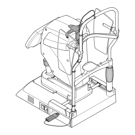
Page 17: Description Of The Device
2 Connecting cable 3 5 holding clips 4 4 green LEDs 5 2 sleeves to insert into the drill holes on the IOLMaster 500 6 USB control for green LED 7 Right and left pins on the holder 8 Protecting cap of USB control 9 2 clip-on side covers for head rest Fig. -
Page 18: Installation
Installation Installation Software update to version 7.7 1 Button for starting software update Fig. 3 Software update To install a new software version from a USB flash drive, proceed as follows: 1. Connect the USB flash drive with the new software version. ... - Page 19 Installation 2. To start the installation routine of the software update, click the Update button of the Program tab in the Settings menu. 3. Follow the instructions on the screen until prompted to reboot. 4. Remove the USB flash drive. When the New patient tab reappears in the Patient manager after the IOLMaster has been rebooted, the software update installation is complete.
-
Page 20: Installation Of Hardware Components
• Insert the two sleeves (2, Fig. 4) into the two upper drill holes (1, Fig. 4) on the right and left side of the IOLMaster 500 facing the patient. • First insert the pin (3 or 5, Fig. 4) into the sleeve on one side of the holder. -
Page 21: Fig. 5 Feeding The Connecting Cable And Inserting The Usb Control
• Now feed the connecting cable (2, Fig. 5) of the Option Reference Image to the center of the head rest. To avoid damage to the cable, pull the IOLMaster 500 back from the head rest as far as it will go (from physician's viewpoint to the left and to the front). -
Page 22: Fig. 6 Mounting The Side Covers
Installation of hardware components 1 Side cover 2 Mounting the side cover on the head rest bar Fig. 6 Mounting the side covers • Attach the side covers (1, Fig. 6) to both rods of the head rest bar above the head rest mount (2, Fig. -
Page 23: Operation Of The Instrument
Operation of the instrument Operation of the instrument User's safety obligations CAUTION – GENERAL HAZARDS The patient should not touch the instrument with his/her hands. In particular, the instrument should not be used as a support or an aid when standing up. -
Page 24: Measurement And Image Capture In Reference Image Mode
Operation of the instrument Measurement and image capture in Reference Image mode A WTW measurement taken preceding the Reference Image mode enables an additional plausibility check of the reference image which may lead to a more successful evaluation of the reference image in certain cases. -
Page 25: Fig. 9 Device Adjustment To Reach Optimum Measurement Position
Operation of the instrument Fig. 9 Device adjustment to reach optimum measurement position It is recommended that the patient blink shortly before the measurement to produce a continuous tear film. This will improve the reflectivity of the cornea. Make sure the patient’s eyelids are outside the lid aperture edges of the eye template (3, Fig. -
Page 26: Fig. 10 Image Capture In Reference Image Mode
Operation of the instrument Several single measurements are taken at short intervals for a single keratometer measurement. Following this, the radii or corneal K's (depending on program settings in the Settings - Measurement tab) of the two main sections will be displayed, together with the respective axial orientation and the astigmatic difference. -
Page 27: Fig. 11 Confirming Successful Data Export
The data record can be exported by clicking on the Send icon if the IOLMaster 500 is connected to a network using a DICOM-enabled data management solution. The data record can also be exported to a USB flash drive which is connected to the device. -
Page 28: Printing The Reference Image
Operation of the instrument Printing the reference image Once the measurements have been completed, the readings and the reference image can be printed. The following print formats are supported (upright format only): A4 (210 x 297 mm), Letter (8.5” x 11.0”), B5 (182 x 257 mm). The printout of the readings may be started in the Option Reference Image mode. -
Page 29: Application Guidelines For Reference Image Measurement
Application guidelines for Reference Image measurement Application guidelines for Reference Image measurement Evaluation of reference image quality Ambient and room lighting conditions of device location The following information refers to ambient lighting conditions of the location where the device is installed. Minimize variations of ambient lighting conditions e.g. -
Page 30: Stray Light From Local Light Sources Or Lateral Sunlight
Application guidelines for Reference Image measurement Stray light from local light sources or lateral sunlight Lateral illumination from local light or reflection sources or from lateral illumination when the sun is low can lead to local reflections or stray light in the sclera. -
Page 31: Eye Is Not Correctly Centered
Application guidelines for Reference Image measurement Eye is not correctly centered The following information refers primarily to the operation of the device. Lateral decentration of the reference image can lead to erroneous evaluations of the reference image quality. Fig. 14 Eye is not correctly centered. -
Page 32: The Palpebral Aperture Is Not Large Enough
Application guidelines for Reference Image measurement The palpebral aperture is not large enough The following information refers primarily to characteristics of the patient's eye. It may be difficult for some patients to open the eye sufficiently wide. Palpebral apertures which are too small prevent accurate detection of vessels near the limbus. -
Page 33: Excessive Eye Movements Prevent Images Of Sufficient Quality From Being Obtained
Application guidelines for Reference Image measurement Excessive eye movements prevent images of sufficient quality from being obtained In some cases, eyes may move considerably during image capture. Excessive eye movements prevent sufficient quality of the reference image. Fig. 16 Excessive eye movements prevent images of sufficient quality from being obtained Error message: "Unstable fixation."... -
Page 34: Few Vessels Near The Limbus
Application guidelines for Reference Image measurement Few vessels near the limbus In some cases the eye may have not enough vessels near the limbus which prevents detection of a sufficient number of vessels. Fig. 17 Not enough vessels near the limbus Error message: "Not enough vessels near the limbus have been found"... -
Page 35: Fluctuations In Keratometer Values
Application guidelines for Reference Image measurement Fluctuations in keratometer values The precision and repeatability of keratometer measurement values, especially those relating to the axial orientation of the main meridians, are of particular significance for measurements in Reference Image mode. Error message: "Borderline keratometry" Fault Axial variations in single measurements of keratometry values are too strong in relation to the astigmatic difference of the main meridians. -
Page 36: Care And Cleaning
Care and cleaning Care and cleaning Do not use acetone and acetone-based cleaning agents to clean the devices, as they could damage the surfaces. 000000-1865-713-GA-en-US-080622... -
Page 37: Technical Data
Technical data Technical data Essential performance of Option Reference Image There is no essential performance. Device specifications Optical radiation Illumination for Option Reference Image Source Wavelength 520 nm Delivered power < 381 µW Ambient conditions for intended use +10 °C to +35 °C Temperature Relative humidity 30 % to 90 %, non condensing... -
Page 38: Abbreviations/Glossary
Abbreviations/Glossary Abbreviations/Glossary Anterior chamber depth Deutsches Institut für Normung (German Standards Institute) European standard Fig. Figure Intraocular lens Light emitting diode Millimeter Personal computer Universal serial bus (standard interface for PC peripherals) White-to-white distance 000000-1865-713-GA-en-US-080622... -
Page 39: Figures
Figures Figures Fig. 1 Warning and information labels on the device ......8 Fig. 2 Option Reference Image ............. 11 Fig. 3 Software update ................. 12 Fig. 4 Mounting the holder ..............14 Fig. 5 Feeding the connecting cable and inserting the USB control ..15 Fig. -
Page 40: Index
Index Index Abbreviations .................... 32 Contraindications ..................6 Country-specific information ............... 6 Description of the device................11 Device classification ..................6 Disposal ...................... 7 Figures ...................... 33 Functional description ................10 Glossary ....................32 Installation ....................12 Labels ......................8 Manufacturer’s declaration ................. - Page 42 Manufacturer Carl Zeiss Meditec AG Goeschwitzer Str. 51-52 07745 Jena Germany Phone: +49 3641 220 333 Fax: +49 3641 220 112 000000-1692-983-GA-en-US-080622 Email: info.meditec@zeiss.com IOLMaster Option Reference Image Internet: www.zeiss.com/med Specifications subject to change...
- Page 44 Manufacturer Carl Zeiss Meditec AG Goeschwitzer Str. 51-52 07745 Jena Germany Phone: +49 3641 220 333 Fax: +49 3641 220 112 Email: info.meditec@zeiss.com Internet: www.zeiss.com/med IOLMaster 500 Option Reference Image Specifications subject to change 000000-1865-713-DokS-en-US-080622...
Need help?
Do you have a question about the IOLMaster 500 and is the answer not in the manual?
Questions and answers