Table of Contents
Advertisement
Quick Links
Advertisement
Table of Contents

Related Manuals for Zeiss PLEX Elite 9000


Summary of Contents for Zeiss PLEX Elite 9000
- Page 1 PLEX® Elite 9000 Version 1.7 Instructions for Use...
- Page 2 © 2018, Carl Zeiss Meditec, Dublin, CA Trademarks All Zeiss products mentioned herein are either registered trade- marks or trademarks of Carl Zeiss Meditec, Inc. in the United States and/or other countries. Windows, Windows Media, Windows Server, and Microsoft are either registered trademarks or trademarks of Microsoft Corpo- ration in the United States and/or other countries.
-
Page 3: Table Of Contents
Instructions for Use Table of Contents 2660021169042 Rev. A 2018-03 Table of Contents Safety and Certifications ................ 9 Symbols and Labels ...................... 9 Definitions .......................... 10 Safety .......................... 10 1.3.1 Product Safety.......................... 11 1.3.2 Product Safety.......................... 14 1.3.3 Optical Safety .......................... 17 1.3.4 Laser Safety and Compliance ...................... 19 1.3.5 Electrical Safety .......................... 19 1.3.6... - Page 4 Table of Contents Instructions for Use 2660021169042 Rev. A 2018-03 2.6.1 New in Version 1.7.......................... 34 System Overview.................. 37 Hardware Overview...................... 37 3.1.1 Acquisition Device ........................... 38 3.1.2 PC .............................. 38 3.1.3 Monitor............................ 39 3.1.4 Network-Attached Storage (NAS) .................... 39 3.1.5 Network Switch.......................... 40 3.1.6 Power Table ............................ 40 Software Overview ...................... 40 3.2.1 Screen Layout.......................... 41...
- Page 5 Instructions for Use Table of Contents 2660021169042 Rev. A 2018-03 Before Every Use .................. 71 Safety During Preparation for Use .................. 71 Prepare the Device for Use .................... 72 Read and Understand Physician Instructions .............. 72 Operation .................... 73 User Login/Logout ...................... 73 8.1.1 Logging In as Operator or Data Analyst ................... 73 8.1.2 Logging Out ............................ 73...
- Page 6 Table of Contents Instructions for Use 2660021169042 Rev. A 2018-03 9.4.8 Image Navigation .......................... 137 Using Presets ........................ 142 9.5.1 About Presets.......................... 142 9.5.2 Show or Hide Presets ........................ 142 9.5.3 Angiography Analysis Presets ...................... 143 9.5.4 Enface and Cube Report Presets .................... 146 9.5.5 Creating Custom Presets........................ 149 Show or Hide the Fundus Image.................. 150 Editing B-Scans......................... 150 Editing Segmentation Results ................... 151...
- Page 7 Instructions for Use Table of Contents 2660021169042 Rev. A 2018-03 11.3 Connecting Review Stations to Instrument Data Archives .......... 178 11.4 Adding a Network Storage Device.................. 179 11.4.1 NAS Device Requirements ...................... 179 11.4.2 Network File Server Minimum Requirements ................. 180 11.4.3 Setting Up a Network File Server (external NAS) ................ 180 Cleaning and Disinfection.................
- Page 8 Table of Contents Instructions for Use 2660021169042 Rev. A 2018-03 15.4.1 Dell Tower 5810.......................... 214 15.4.2 Network Attached Storage ...................... 214 15.4.3 DLink DGS-1008 Switch ........................ 215 15.4.4 Supporting Power Table ........................ 216 15.4.5 Dimensions and Weight ........................ 216 15.5 Environmental Conditions.................... 216 15.5.1 Environmental Conditions of Use.................... 216 15.5.2 Storage Conditions........................ 217 15.5.3...
-
Page 9: Safety And Certifications
Instructions for Use 1 Safety and Certifications 2660021169042 Rev. A 2018-03 1.1 Symbols and Labels 1 Safety and Certifications Before using the PLEX® Elite 9000, you must fully understand potential safety hazards. Read the following safety warnings and cautions in their entirety before using the instrument. Additional warnings and cautions are found throughout the instructions for use. -
Page 10: Definitions
1 Safety and Certifications Instructions for Use 1.2 Definitions 2660021169042 Rev. A 2018-03 Serial Number Catalog Number/Part Number Model Number Certification mark of CSA – Nationally recognized test laboratory for US and Canada Disposal of the Product within the E.U. Do not dispose via domestic waste disposal system or communal waste disposal facility. -
Page 11: Product Safety
An ungrounded Device WARNING! could lead to electric shock. Do not remove or disable the ground pin. Only an authorized ZEISS service representative may service the instrument. Only an authorized ZEISS representative may install the instrument. Installation of devices and systems by persons not autho-... - Page 12 1 Safety and Certifications Instructions for Use 1.3 Safety 2660021169042 Rev. A 2018-03 Device proximity to flammable gases or vapors WARNING! may cause ignition. Do NOT use in the presence of flammable anesthetics, or oxidizing gases such as nitrous oxide and pure oxygen. Opening Instrument Covers WARNING! can lead to exposure to electrical and optical hazard.
- Page 13 Only authorized ZEISS personnel are authorized to modify or dismantle the instrument or its components. Reconfiguring system components on the table, or adding...
-
Page 14: Product Safety
An ungrounded Device WARNING! could lead to electric shock. Do not remove or disable the ground pin. Only an authorized ZEISS service representative may service the instrument. Only an authorized ZEISS representative may install the instrument. Installation of devices and systems by persons not autho-... - Page 15 Use only the accessories, transducers, and cables specified or provided by ZEISS. Device proximity to flammable gases or vapors WARNING! may cause ignition.
- Page 16 Only authorized ZEISS personnel are authorized to modify or dismantle the instrument or its components. 16 / 246 2660021169042 Rev. A 2018-03...
-
Page 17: Optical Safety
CAUTION! non-system devices or components to the table, or replacing original system components with substitutes not approved by ZEISS could result in failure of the table height adjustment mechanism, instability of the table, tipping and damage to the instrument, and injury to operator and patient. - Page 18 1 Safety and Certifications Instructions for Use 1.3 Safety 2660021169042 Rev. A 2018-03 Patient injection with photo–dynamic therapy (PDT) WARNING! treatment drugs, such as Visudyne® could lead to unintended exposure and uncontrolled treatment of neovascular vessels. Do not scan patients who have been injected with photo– dynamic therapy (PDT) treatment drugs, such as Visudyne®, in the previous 48 hours.
-
Page 19: Laser Safety And Compliance
When using a printer in the USB configuration, always power the printer through an isolation transformer. Some ZEISS equipment comes with an isolation transformer that may be 2660021169042 Rev. A 2018-03... - Page 20 If you do use a peripheral device that conforms with the requirements in this section but is not supplied by Zeiss, do not install any unapproved third party software on the instrument. 20 / 246...
-
Page 21: Networking Safety
MANCE OF THE FOLLOWING ACTIVITIES. ZEISS does not support the following network activities, although they may be possible: • Printing with a printer not approved by ZEISS for use with this instrument. Refer to our website for the current list of approved hardware and software. -
Page 22: Record And Data Safety
Read the user documentation. Follow directions carefully. Do not make upgrades, or carry out repairs or modifications, without specific guidance and instruction from ZEISS or an authorized ZEISS represenative. The following activities are prohibited using the PLEX® Elite 9000 instrument: •... -
Page 23: Electromagnetic Emissions
Installing or putting the device into service without regard to WARNING! EMC information provided may void your ZEISS instrument warranty, result in damage to the instrument and/or compromise safety for patients and operators. This instrument has special EMC precaution requirements and needs to be installed and put into service according to the EMC information provided herein. - Page 24 1 Safety and Certifications Instructions for Use 1.4 Electromagnetic Compatibility (EMC) 2660021169042 Rev. A 2018-03 Voltage dips, short inter- <5% UT (>95% dip <5% UT (>95% dip Mains power quality should be ruptions, and voltage in UT) for 0,5 cycle in UT) for 0,5 that of a typical commercial or variations on power supply...
- Page 25 Instructions for Use 1 Safety and Certifications 2660021169042 Rev. A 2018-03 1.4 Electromagnetic Compatibility (EMC) Guidance and manufacturer’s declaration – electromagnetic immunity The PLEX® Elite 9000 is intended for use in the electromagnetic environment specified below. The customer or user of the PLEX® Elite 9000 should assure that it is used in such an environment. Immunity Test IEC 60601 test level Compliance...
- Page 26 1 Safety and Certifications Instructions for Use 1.4 Electromagnetic Compatibility (EMC) 2660021169042 Rev. A 2018-03 Recommended separation distances between portable and mobile RF communications equipment and the PLEX® Elite 9000 The PLEX® Elite 9000 is intended for use in an electromagnetic environment in which radiated RF distur- bances are controlled.
-
Page 27: Operator Training And Equipment Maintenance
ü Regular technical safety inspections must be carried out as specified for this device by any and all applicable national regulations. ü Equipment inspections may only be performed by Zeiss or Zeiss- qualified personnel. Comply with the specified maintenance intervals. -
Page 28: Notification Of Serious Incident
Making changes to equipment without first consulting your WARNING! ZEISS Field Representative could result in the equipment being Out of Compliance. Any additional equipment connected to medical electrical devices must demonstrably comply with the applicable IEC or ISO standards (e.g. -
Page 29: Introduction
Instructions for Use 2 Introduction 2660021169042 Rev. A 2018-03 2.1 Scope 2 Introduction 2.1 Scope 2.1.1 Intended Use The PLEX® Elite 9000, a Swept-Source OCT [SS-OCT], is a non- contact, high resolution, wide field-of-view tomographic and biomicroscopic imaging device intended for in-vivo viewing, axial cross-sectional and three-dimensional imaging of posterior ocular structures. -
Page 30: Essential Performance
2 Introduction Instructions for Use 2.2 Subject/Patient Profile 2660021169042 Rev. A 2018-03 2.1.4 Essential Performance The PLEX® Elite 9000 is a retinal imaging device intended to be used as a non-contact, diagnostic imaging instrument for in vivo viewing, axial cross-sectional imaging, and three-dimensional imaging of ocular structures. -
Page 31: Job Requirements (Operators)
Instructions for Use 2 Introduction 2660021169042 Rev. A 2018-03 2.4 Data Analyst Profile • Able to work with elderly patients and those with disabilities 2.3.3 Job Requirements (Operators) Must be able to perform all of the following operations: • Power on the unit and log on •... -
Page 32: Job Requirements (Analysts)
2 Introduction Instructions for Use 2.5 User Documentation 2660021169042 Rev. A 2018-03 • Able to work with elderly patients and those with disabilities 2.4.3 Job Requirements (Analysts) • Accurately identify ocular anomalies • Have a history of correct diagnoses of eye disease or work solely within a research environment •... -
Page 33: Conventions Used In This Document
• My documents > Documents 2.5.6 Questions and Comments If you have questions or comments regarding this user documen- tation, or about the device, contact ZEISS Service. Contact infor- mation can be found at www.zeiss.com/med. 2.6 PLEX® Elite 9000 Technology PLEX®... -
Page 34: New In Version 1.7
2 Introduction Instructions for Use 2.6 PLEX® Elite 9000 Technology 2660021169042 Rev. A 2018-03 In Swept Source OCT, spectral data is acquired over time by illumi- nating the interferometer with a light source that produces only a very narrow optical frequency band at a given moment, and then rapidly shifts that band across a broad spectrum. - Page 35 Instructions for Use 2 Introduction 2660021169042 Rev. A 2018-03 2.6 PLEX® Elite 9000 Technology non HD HD 51 Line Table 2: Cube 6mmx6mm B-Scan Examples 2.6.1.2 Fast Montage (15x9) A new scan option, Montage Angio (15mmx9mm), acquires two Angio 15mmx9mm scans at central fixation combined to form a single image with a FOV greater than 50 degrees.
- Page 36 2 Introduction Instructions for Use 2.6 PLEX® Elite 9000 Technology 2660021169042 Rev. A 2018-03 36 / 246 2660021169042 Rev. A 2018-03...
-
Page 37: System Overview
Instructions for Use 3 System Overview 2660021169042 Rev. A 2018-03 3.1 Hardware Overview 3 System Overview 3.1 Hardware Overview The PLEX® Elite 9000 will be unpacked and installed for you (components shown below). 4 5 6 PLEX® Elite 9000 Acquisition PC (Workstation) Device Computer Shelf... -
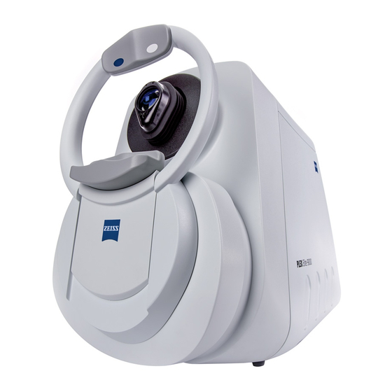
Page 38: Acquisition Device
3 System Overview Instructions for Use 3.1 Hardware Overview 2660021169042 Rev. A 2018-03 3.1.1 Acquisition Device Figure 3: PLEX® Elite 9000 Acquisition Device Port for External Fixation Arm 2 Head Rest Imaging Aperture Dual Chin Rest with Automatic Right/Left Sensors Motorized Patient Alignment Unit 3.1.2 PC The PC provides the data and image processing for the PLEX®... -
Page 39: Monitor
Instructions for Use 3 System Overview 2660021169042 Rev. A 2018-03 3.1 Hardware Overview 3.1.3 Monitor Figure 5: Monitor Function Buttons On/Off Button NOTE! It is not necessary to turn off the monitor. 3.1.4 Network-Attached Storage (NAS) Figure 6: Network Attached Storage Device Status Indicators On/Off Button NOTE! It is not necessary to turn the NAS off. -
Page 40: Network Switch
3 System Overview Instructions for Use 3.2 Software Overview 2660021169042 Rev. A 2018-03 3.1.5 Network Switch The network switch is provided to allow access to your institution's network (see Networking [} 175]). Figure 7: Network Switch (Back) Ethernet Ports 3.1.6 Power Table Cables that connect components are routed under the table. -
Page 41: Screen Layout
Instructions for Use 3 System Overview 2660021169042 Rev. A 2018-03 3.2 Software Overview 3.2.1 Screen Layout Figure 9: Screen Layout Pos. Name Explanation Toolbar Menus common to all screens Work Area Varies depending on mode and function Navigation Bar Status indicator and mode selection common to all screens 3.2.2 Toolbar Each PLEX®... - Page 42 3 System Overview Instructions for Use 3.2 Software Overview 2660021169042 Rev. A 2018-03 Option Description Enabled in User Type(s) Archive Patient ID Mode Operator Management Preferences Tabs: Patient ID Mode Operator • Archive/Synchronize: Enable alerts to archive exams during instrument startup or shutdown. •...
- Page 43 Instructions for Use 3 System Overview 2660021169042 Rev. A 2018-03 3.2 Software Overview 3.2.2.3 Tools Menu Figure 12: Tools Menu Option Description Enabled in User Type(s) Live Fundus Turns the live fundus overlay on or off. Fundus Acquire mode Operator Overlay: overlay is on by default.
-
Page 44: Navigation
3 System Overview Instructions for Use 3.2 Software Overview 2660021169042 Rev. A 2018-03 Option Description Enabled in User Type(s) Options > Create, edit, or delete categories for patient records. Patient ID Mode Operator Categories\ Admin Options > Enables you to customize your PLEX® Elite 9000 and All modes Admin Institution Edit... - Page 45 Instructions for Use 3 System Overview 2660021169042 Rev. A 2018-03 3.2 Software Overview 3.2.3.1 Navigation Buttons Figure 14: Navigation Buttons Button Description Opens ID Patient mode. Opens Acquisition mode. NOTE! This button is only active when a patient is selected. Opens Analysis mode. NOTE! This button is only active when a patient with saved scans is selected.
-
Page 46: Basic Screens
3 System Overview Instructions for Use 3.2 Software Overview 2660021169042 Rev. A 2018-03 3.2.4 Basic Screens Figure 15: Basic Screen Examples Pos. Name Explanation Patient ID Screen Select or add a patient (see Find Existing Patient Screen [} 74]). Acquire Screen (Instrument Only) Acquire scans for the selected patient (see Acquire Angio, Cube, and HD 51 Scans Screen [} 83] Acquire HD Spotlight Screen [} 88], and Acquire Montage Screen [} 92]). -
Page 47: Installation
On arrival, the ZEISS Field Representative will carefully unpack and assemble all system components at the location you have selected for its placement. Once the PLEX® Elite 9000 is assembled, a ZEISS Service Representative will set up an appointment to install the PLEX®... -
Page 48: Install Review Station Software
NOTE onto the instrument could result in instability and incorrectly captured data. Unless otherwise instructed by an authorized ZEISS Represen- tative, do not attempt to install software on your PLEX® Elite 9000. These instructions are provided only for installing PLEX®... -
Page 49: Software And Document Media
Instructions for Use 4 Installation 2660021169042 Rev. A 2018-03 4.3 Install Review Station Software 4.3.1 Software and Document Media PLEX® Elite 9000 comes with a USB case that contains two flash drives. Content Label Software to install on review stations. User Documentation. -
Page 50: Review Station Performance
Press the Print Screen button on your keyboard and save the error message to inform ZEISS Customer Support: 800–341– 6968. Outside the U.S., contact your local Zeiss distributor. þ The Review Station fulfills the minimum system requirements for the Review Software (see: Review Station Requirements [} 49]). - Page 51 Instructions for Use 4 Installation 2660021169042 Rev. A 2018-03 4.3 Install Review Station Software 2. Navigate to the USB drive. 3. Double-click Setup.exe. Installation takes a few moments to prepare before the NOTE installation wizard opens. ð The installation wizard opens, prepares the installation and opens installation settings.
- Page 52 4 Installation Instructions for Use 4.3 Install Review Station Software 2660021169042 Rev. A 2018-03 The review software installs in several steps and takes a few NOTE minutes to complete. A series of progress bars indicate the progress of each step. ð...
-
Page 53: Installing User Documentation
Instructions for Use 4 Installation 2660021169042 Rev. A 2018-03 4.4 Installing User Documentation 9. Select ZDB.ib and click Open. 10. Remove the USB flash drive from the USB port and return it to the media kit. 11. Configure the Review Station: Configuring an Additional Instrument or Review Station [} 58]. - Page 54 Empty page, for your notes...
-
Page 55: Startup And Shutdown
Instructions for Use 5 Startup and Shutdown 2660021169042 Rev. A 2018-03 5.1 System Startup 5 Startup and Shutdown 5.1 System Startup Unsecured Logins NOTE may result in unauthorized access or inaccurate record-keeping. Create individual user accounts for each staff member. Staff members should log out after every use. - Page 56 5 Startup and Shutdown Instructions for Use 5.2 System Shutdown 2660021169042 Rev. A 2018-03 To turn off the PLEX® Elite 9000, press the PC power button. It is not necessary to turn off the instrument or any other system components or peripherals. Action 1.
-
Page 57: Configuring Software
Instructions for Use 6 Configuring Software 2660021169042 Rev. A 2018-03 6.1 System Administration 6 Configuring Software 6.1 System Administration Logging in as the System Administrator allows access to additional configuration, including: • Managing User Accounts [} 61] • Editing the Instrument Identifier [} 61] •... - Page 58 6 Configuring Software Instructions for Use 6.1 System Administration 2660021169042 Rev. A 2018-03 Task Required (if using DICOM) Set up DICOM connection (Enabling Automatic Worklist Search (DICOM) [} 68]). Required (if networked) Set internet protocol (Setting the Preventive Maintenance Schedule [} 70]). Recommended Configure Windows updates (Configuring Windows Automatic Updates [} 176]).
-
Page 59: Log In As Admin
Instructions for Use 6 Configuring Software 2660021169042 Rev. A 2018-03 6.1 System Administration Requirement Task Required (if using DICOM) Setup up DICOM connection (Enabling Automatic Worklist Search (DICOM) [} 68]). Required (if networked) Set internet protocol (Setting the Preventive Maintenance Schedule [} 70]). - Page 60 6 Configuring Software Instructions for Use 6.1 System Administration 2660021169042 Rev. A 2018-03 If you change the Issuer of Patient ID, the change will apply to future patient records; patient information already in the database does not change. 6.1.3.2 Editing Your Institution Information You must restart the software for the Institution Name NOTE changes to appear in report headers.
-
Page 61: Managing User Accounts
Instructions for Use 6 Configuring Software 2660021169042 Rev. A 2018-03 6.1 System Administration 6.1.3.3 Editing the Instrument Identifier You must create a unique name for each PLEX® Elite 9000 instrument and review station. Tip: Use Station Names meaningful When configuring these settings, important instrument information to your organization (for example: displays, including: "Imaging Room 215"). - Page 62 6 Configuring Software Instructions for Use 6.1 System Administration 2660021169042 Rev. A 2018-03 6.1.4.1 User Types Operator Referring Requesting Reading Physician Physician Physician Ordering ✔ ✔ scans Reviewing ✔ scans Acquiring ✔ scans Table 8: User Types and Permissions 6.1.4.2 Viewing User Accounts Only Administrators can complete this task.
- Page 63 Instructions for Use 6 Configuring Software 2660021169042 Rev. A 2018-03 6.1 System Administration Action 1. Select Tools >Options > Users. ð The Staff Registration dialog opens listing the users already added to the system. If no users exist, the list is empty.
- Page 64 6 Configuring Software Instructions for Use 6.1 System Administration 2660021169042 Rev. A 2018-03 First Name, Last Name and Password are case-sensitive. NOTE When you add a new user, you must provide at least one name (last name or first name). All other fields are optional. To edit a user: þ...
-
Page 65: Managing Patient Categories
Instructions for Use 6 Configuring Software 2660021169042 Rev. A 2018-03 6.2 Managing Patient Categories 2. Select the user you want to delete. 3. Click Delete. ð A confirmation opens. 4. Click OK. 6.2 Managing Patient Categories You can create custom categories for patient records. Then you can use categories to identify a group of patients that fit into your category (or combination of categories) using Advanced Search [} 75]. -
Page 66: Adding A Category
6 Configuring Software Instructions for Use 6.2 Managing Patient Categories 2660021169042 Rev. A 2018-03 6.2.2 Adding a Category To add a category: þ Logging In as Operator or Data Analyst [} 73] Prerequisite Action 1. Select Tools > Options > Categories. ð... -
Page 67: Deleting A Category
Instructions for Use 6 Configuring Software 2660021169042 Rev. A 2018-03 6.3 Setting Preferences 3. Update the category information. 4. Click Save. 6.2.4 Deleting a Category You cannot edit categories created by another institution. NOTE To delete a category: Prerequisite þ Logging In as Operator or Data Analyst [} 73] Action 1. -
Page 68: Setting The Default Patient Screen
6 Configuring Software Instructions for Use 6.3 Setting Preferences 2660021169042 Rev. A 2018-03 3. To alert the operator of un-archived data each time the instrument starts up, check Startup . 4. To alert the operator of un-archived data each time the instrument shuts down, check Shutdown. -
Page 69: Setting The Internet Protocol Version
Instructions for Use 6 Configuring Software 2660021169042 Rev. A 2018-03 6.3 Setting Preferences 2. Select the DICOM Archive tab. 3. Check Enable Auto-Query of Modality Worklist. ü The DICOM worklist automatically populates today's Result patients list. 6.3.4 Setting the Internet Protocol Version PLEX®... -
Page 70: Setting The Preventive Maintenance Schedule
6 Configuring Software Instructions for Use 6.3 Setting Preferences 2660021169042 Rev. A 2018-03 6.3.5 Setting the Preventive Maintenance Schedule PLEX® Elite 9000 instruments require regular maintenance. The frequency of this maintenance depends on how much your insti- tution uses the instrument. To set the maintenance schedule: þ... -
Page 71: Before Every Use
Instructions for Use 7 Before Every Use 2660021169042 Rev. A 2018-03 7.1 Safety During Preparation for Use 7 Before Every Use 7.1 Safety During Preparation for Use Improper operator training CAUTION! could lead to poor scan quality, damage to system components, or inadvertent patient safety compromise. -
Page 72: Prepare The Device For Use
7 Before Every Use Instructions for Use 7.2 Prepare the Device for Use 2660021169042 Rev. A 2018-03 Figure 16: Patient Pinch Hazard Area to Avoid 7.2 Prepare the Device for Use Action 1. Wipe the chinrest and forehead rest with an alcohol pad and allow it to dry. -
Page 73: Operation
Instructions for Use 8 Operation 2660021169042 Rev. A 2018-03 8.1 User Login/Logout 8 Operation 8.1 User Login/Logout 8.1.1 Logging In as Operator or Data Analyst You are prompted to log in: • After system startup • After application logout For information about the features available for operators, data analysts and administrators, refer to: User Types [} 62]. -
Page 74: Select The Patient
8 Operation Instructions for Use 8.2 Select the Patient 2660021169042 Rev. A 2018-03 8.2 Select the Patient You must select the appropriate patient record before you scan or analyze images. You can add a new patient or select an existing patient. - Page 75 Instructions for Use 8 Operation 2660021169042 Rev. A 2018-03 8.2 Select the Patient Pos. Symbol Name Explanation Search Quick search to find a patient when all or part of their last name or ID is known. Advanced Search Additional criteria to narrow the search results further or to search using different known criteria.
- Page 76 8 Operation Instructions for Use 8.2 Select the Patient 2660021169042 Rev. A 2018-03 Patient ID Enter the Patient ID. If necessary, the clinician or doctor who issued the ID. The obscured ID is assigned to all patients on obscuration. See Patient Privacy [} 156] for information on the Obscured ID field.
-
Page 77: Select From Today's Patients
Instructions for Use 8 Operation 2660021169042 Rev. A 2018-03 8.2 Select the Patient 8.2.2 Select from Today's Patients 8.2.2.1 View Today's Patients Screen Figure 18: View Today's Patients Tab Pos. Name Explanation Results Lists patient information for patients scheduled for a PLEX® Elite 9000 exam today (from the electronic medical record system). -
Page 78: Prepare The Patient
8 Operation Instructions for Use 8.3 Prepare the Patient 2660021169042 Rev. A 2018-03 2. To refresh this list, click Refresh List. 3. Select a patient's name. 4. To acquire a scan for this patient, click Acquire. 8.3 Prepare the Patient 8.3.1 Dilating the Patient's Eyes (Optional) You do not need to dilate the patient's eye(s) for scans using NOTE... - Page 79 Instructions for Use 8 Operation 2660021169042 Rev. A 2018-03 8.3 Prepare the Patient If necessary, remind the patient to rest their head gently against the head rest so their forehead moves easily with the chinrest as it moves left, right, up, or down. The video image of the eye is clearest when the instrument is the right distance from the patient.
-
Page 80: Determine Scan Type
8 Operation Instructions for Use 8.4 Determine Scan Type 2660021169042 Rev. A 2018-03 8. After the capture is complete, instruct the patient to relax but maintain chinrest position while the technician reviews the scan. 9. If scan quality is not sufficient, retake the scan. 10. - Page 81 Instructions for Use 8 Operation 2660021169042 Rev. A 2018-03 8.4 Determine Scan Type PLEX® Elite 9000 Angiography uses differences between B-scans to generate contrast associated with the motion of blood through the vasculature. Angiography uses swept-source frequency filtering to generate images with detailed vasculature. To image vascular flow, each B-scan in the scan pattern is repeated several times consecutively.
-
Page 82: Acquire Data (Scan)
8 Operation Instructions for Use 8.5 Acquire Data (Scan) 2660021169042 Rev. A 2018-03 – Angle: adjustable -89 to 90 degrees – Position: anywhere on the fundus image You can set the number of Frames (scan repetitions): 10, 20, 30, 40, 50, 60, 70, 80, 90, or 100. •... - Page 83 Instructions for Use 8 Operation 2660021169042 Rev. A 2018-03 8.5 Acquire Data (Scan) 8.5.1.1 Acquire Angio, Cube, and HD 51 Scans Screen Figure 19: Angio Scan, Cube Scan, and HD 51 Scan: Acquire Screen Pos. Symbol Name Explanation <Select Scan Selection Selection list of scans available for OD (right eye) and one>...
- Page 84 8 Operation Instructions for Use 8.5 Acquire Data (Scan) 2660021169042 Rev. A 2018-03 Pos. Symbol Name Explanation Live Fundus Viewport Displays the live image showing the scan pattern Fundus limits. Viewport Prior Scan Identifies Selected Prior Scan Replicates the settings of a prior scan (to compare same scans of the same eye using the same settings).
- Page 85 Instructions for Use 8 Operation 2660021169042 Rev. A 2018-03 8.5 Acquire Data (Scan) Pos. Symbol Name Explanation Live B- Scan Viewport Auto and Manual B-Scan Automatically enhances the live scan or use the Enhancement arrows to adjust manually. Center Live Scan Automatically center the live scan or use the arrows to adjust manually.
- Page 86 8 Operation Instructions for Use 8.5 Acquire Data (Scan) 2660021169042 Rev. A 2018-03 ð The Acquire Screen opens. 2. Select the appropriate scan (1) under OD or OS. ð The chinrest moves into place for the selected scan. 3. Left-click on the center of the pupil (2) in the viewport (3). ð...
-
Page 87: Acquire Hd Spotlight Scans
Instructions for Use 8 Operation 2660021169042 Rev. A 2018-03 8.5 Acquire Data (Scan) 9. To adjust B-scan (9) image quality, fine-tune Enhance (10) (polarization) settings. 10. To adjust B-scan (9) image centering, fine-tune Center (11) (Z- offset) settings. 11. To turn on FastTrac, click the FastTrac icon (12). ð... - Page 88 8 Operation Instructions for Use 8.5 Acquire Data (Scan) 2660021169042 Rev. A 2018-03 8.5.2.1 Acquire HD Spotlight Screen This section describes the unique elements of the HD Spotlight acquire screen. For information about the common elements of acquire screens, refer to: Acquire Angio, Cube, and HD 51 Scans Screen [} 83].
- Page 89 Instructions for Use 8 Operation 2660021169042 Rev. A 2018-03 8.5 Acquire Data (Scan) 8.5.2.2 Acquiring HD Spotlight Scans To repeat the settings for a prior scan, see: Repeating an Earlier Scan [} 96]. To acquire HD scans: þ Select the Patient [} 74] Prerequisite þ...
- Page 90 8 Operation Instructions for Use 8.5 Acquire Data (Scan) 2660021169042 Rev. A 2018-03 ð The fixation target (green crosshair) moves to the location selected. 7. Click Optimize (7). 8. To adjust image brightness or make other fine adjustments for any viewport, click the corresponding Fine Adjustment (8) tool and make adjustments.
-
Page 91: Acquire Montage Angio Data
Instructions for Use 8 Operation 2660021169042 Rev. A 2018-03 8.5 Acquire Data (Scan) 18. Click Capture (19). ð The Check Quality screen opens. 19. Check Scan Quality [} 97]. 8.5.3 Acquire Montage Angio Data When you acquire a montage, PLEX® Elite 9000 captures a set series of individual images-- each in a different area-- and stitches them into a composite image. - Page 92 8 Operation Instructions for Use 8.5 Acquire Data (Scan) 2660021169042 Rev. A 2018-03 8.5.3.1 Acquire Montage Screen This section describes the unique elements of the montage acquire screen. For information about the common elements of acquire screens, refer to: Acquire Angio, Cube, and HD 51 Scans Screen [} 83].
- Page 93 Instructions for Use 8 Operation 2660021169042 Rev. A 2018-03 8.5 Acquire Data (Scan) Pos. Symbol Name Explanation Scan Positions (12mm x Preset positions for each of the five 12mm) component scans that are stitched together to create a 12mm x 12 mm montage.
- Page 94 8 Operation Instructions for Use 8.5 Acquire Data (Scan) 2660021169042 Rev. A 2018-03 ð The chinrest moves into place for the selected scan. 3. To change the FOV, click the FOV (2) appropriate for the patient. 4. Left-click on the center of the pupil (3) in the viewport (4). ð...
- Page 95 Instructions for Use 8 Operation 2660021169042 Rev. A 2018-03 8.5 Acquire Data (Scan) 8. To adjust image brightness or make other fine adjustments for any viewport, click the corresponding Fine Adjustment (8) tool and make adjustments. (B-Scan viewport indicated.) 9. To adjust B-scan (9) image quality, fine-tune Enhance (10) (polarization) settings.
-
Page 96: Repeating A Prior Scan (Track To Prior)
8 Operation Instructions for Use 8.5 Acquire Data (Scan) 2660021169042 Rev. A 2018-03 17. To complete the montage before all scans are acquired, click Done (18). 18. When all scans are captured, click Finish (19). ð The Check Quality screen opens. 19. -
Page 97: Check Scan Quality
Instructions for Use 8 Operation 2660021169042 Rev. A 2018-03 8.6 Check Scan Quality 2. To view the details of a prior scan, select it. 3. Select the scan with the settings you want to repeat. 4. Click OK. ð If the prior scan used FastTrac, the current scan also sets FastTrac (2) on. -
Page 98: Quality Check Screen (Angio)
8 Operation Instructions for Use 8.6 Check Scan Quality 2660021169042 Rev. A 2018-03 8.6.1 Quality Check Screen (Angio) Angio quality check provides the standard set of tools for reviewing the scanned images before you save them. The screen is the same for all sizes of Angio Scans. - Page 99 Instructions for Use 8 Operation 2660021169042 Rev. A 2018-03 8.6 Check Scan Quality Pos. Symbol Name Explanation Scan Details Signal Strength Indicates the structure image strength of the scan (%). Fundus Image Indicates the fundus image strength of the scan (%). Tracked During Indicates whether FastTrac was on or off during the Scan...
-
Page 100: Quality Check Screen (Montage)
8 Operation Instructions for Use 8.6 Check Scan Quality 2660021169042 Rev. A 2018-03 8.6.2 Quality Check Screen (Montage) This description includes only features unique to the montage screen. For general Quality Check screen features, refer to: Quality Check Screen (Angio) [} 98]. Figure 23: Angio Montage Quality Check Screen Pos. -
Page 101: Checking Scan Quality
Instructions for Use 8 Operation 2660021169042 Rev. A 2018-03 8.6 Check Scan Quality Pos. Symbol Name Explanation Rescan Options Indicates which component scans of the montage exist and selects which scans to retake. Indicates the component scan exists. Check to indicate which scans to retake. Rescan Begin scan sequence for selected scan(s). -
Page 102: Acceptance Criteria
8 Operation Instructions for Use 8.6 Check Scan Quality 2660021169042 Rev. A 2018-03 6. Scan is complete in all windows (no missing data). 7. Light intensity is uniform across the image. 8. Scan passes: RPE Acceptance Criteria [} 103]. Retina is not too low in the scan, which impacts sub-RPE slice detection. - Page 103 Instructions for Use 8 Operation 2660021169042 Rev. A 2018-03 8.6 Check Scan Quality 8.6.4.1 RPE Acceptance Criteria Test Pass Fail Explanation Retina Retina is in an Retina is too low in the scan If the retinal tissue is captured too Position appropriate position low in the axial FOV of the scan,...
- Page 104 8 Operation Instructions for Use 8.6 Check Scan Quality 2660021169042 Rev. A 2018-03 8.6.4.3 Decorrelation Tails Acceptance Criteria Test Pass Fail Explanation Bright No Decorrelation Decorrelation Tails Bright shadows of more superficial vessels that Tails; signal Appear appear in posterior layers are decorrelation tails. detected shows Decorrelation tails result from light that passes •...
- Page 105 Instructions for Use 8 Operation 2660021169042 Rev. A 2018-03 8.6 Check Scan Quality EnFace B-Scan Explanation • Boundary lines that determine the enface image appear as pink dotted lines overlying the B-scan. • B-scan shows a bright area not associated with pathological flow.
- Page 106 Empty page, for your notes...
-
Page 107: Analyzing Exam Data And Creating Reports
Instructions for Use 9 Analyzing Exam Data and Creating Reports 2660021169042 Rev. A 2018-03 9 Analyzing Exam Data and Creating Reports Using the Analysis and Report screens, you can view, group, characterize, measure, annotate, and adjust scanned data in multiple ways and save the adjusted scans and create reports. -
Page 108: Analysis And Report Screen Elements
9 Analyzing Exam Data and Creating Reports Instructions for Use 9.1 Analysis and Report Screen Elements 2660021169042 Rev. A 2018-03 9.1 Analysis and Report Screen Elements Screen elements common to the analysis and report screens are described below. Figure 24: Analysis and Report Screens Pos. -
Page 109: Reports
Instructions for Use 9 Analyzing Exam Data and Creating Reports 2660021169042 Rev. A 2018-03 9.2 Reports Pos. Symbol Name Explanation Options Set for Scan Capture: FastTrac Indicates that the scan was created using FastTrac. Comparison Indicates that the operator retook the scan using a prior scan's settings. - Page 110 9 Analyzing Exam Data and Creating Reports Instructions for Use 9.2 Reports 2660021169042 Rev. A 2018-03 Angiography provides non-invasive, high quality images of the retinal and choroidal vasculature. Ten Preset slabs on the left side of the Angiography Analysis screen show calculated retinal layers.
- Page 111 Instructions for Use 9 Analyzing Exam Data and Creating Reports 2660021169042 Rev. A 2018-03 9.2 Reports Pos. Symbol Name Explanation Fundus Image Displays or hides the fundus Image over the AngioPlex and Structure images. Combining structural and functional information of the retinal area of interest can provide greater insight into retinal pathologies and increase diagnostic accuracy.
- Page 112 9 Analyzing Exam Data and Creating Reports Instructions for Use 9.2 Reports 2660021169042 Rev. A 2018-03 Pos. Symbol Name Explanation B-Scan Displays the selected slab layer (see Image Navigation [} 137]). NOTE! Drag the segmentation lines to change the boundaries. AngioPLEX Displays the retinal structure to Structure reference along side the AngioPLEX Image.
-
Page 113: En Face Report
Instructions for Use 9 Analyzing Exam Data and Creating Reports 2660021169042 Rev. A 2018-03 9.2 Reports 9.2.1.3.1 Data Cube Planes If you consider the data as a cube, the B-scan shows the slice data in planes parallel to the front of the cube or the side of the cube as shown below. - Page 114 9 Analyzing Exam Data and Creating Reports Instructions for Use 9.2 Reports 2660021169042 Rev. A 2018-03 cross-sections and retinal vessels as landmarks, the images can be correlated to other fundus imaging modalities and used to precisely locate certain kinds of abnormalities. 9.2.2.1 En Face Report Screen Figure 27: En Face Report Screen Pos.
-
Page 115: Cube Report
Instructions for Use 9 Analyzing Exam Data and Creating Reports 2660021169042 Rev. A 2018-03 9.2 Reports 9.2.3 Cube Report The PLEX® Elite 9000 Cube Report provides interactive OCT images. The Fundus Image can be overlaid on the selected OCT image. Each scan shows an associated 3-D thickness map, the colors of which denote Macular thickness in micrometers (µm). -
Page 116: Ou Cube Report
9 Analyzing Exam Data and Creating Reports Instructions for Use 9.2 Reports 2660021169042 Rev. A 2018-03 Pos. Explanation Pos. Explanation Slice Navigator (horizontal blue line) OCT Fundus Image (Current Exam) Fundus Image (Previous Exam) Horizontal Slices (B-Scans) for Selected Scan Data 3D Thickness Map for Selected Scan Data Color Code for Thickness Overlays... -
Page 117: Spotlight Report
Instructions for Use 9 Analyzing Exam Data and Creating Reports 2660021169042 Rev. A 2018-03 9.2 Reports 9.2.4.1 OU Cube Report Screen Figure 29: OU Cube Report Screen Pos. Explanation Slab Presets: Predefined views that reflect specific layers within the retina (See: Using Presets [} 142]). -
Page 118: High Definition Images Report Screen
9 Analyzing Exam Data and Creating Reports Instructions for Use 9.2 Reports 2660021169042 Rev. A 2018-03 9.2.5.1 Spotlight Report Screen Figure 30: HD Spotlight Report (12 mm) 10-100X Pos. Explanation HD Spotlight Option Buttons OCT Image and HD Spotlight Tomogram Prior Scan OCT Image and HD Spotlight Tomogram 9.2.6 High Definition Images Report Screen High Definition Images Screen is for HD 51 scans. - Page 119 Instructions for Use 9 Analyzing Exam Data and Creating Reports 2660021169042 Rev. A 2018-03 9.2 Reports 9.2.6.1 High Definition Images Report Screen Figure 31: High Definition Images Report Screen Pos. Name Explanation Hides or displays the fundus image. Selects the prior scan. Displays only the prior scan.
-
Page 120: Opening A Report Or Analysis
Displays an image 1024 A-scans and 1536 axial pixels. Pixel compresses the image horizontally making retinal layers appear thicker for better visual detail. Displays the default Zeiss image display of 2:1 pixel ratio Displays an anatomically accurate image. OCT Image HD Tomogram 9.3 Opening a Report or Analysis... -
Page 121: Comparing The Current And Prior Scans
Instructions for Use 9 Analyzing Exam Data and Creating Reports 2660021169042 Rev. A 2018-03 9.4 Working with Viewport Images 9.4.1 Comparing the Current and Prior Scans You can compare Angio images over time to see changes in vascu- lature and observe signs of degradation or improvement. The option is only available when a patient has the same scan repeated on different visits. -
Page 122: Hide Or Show A Fundus Overlay
9 Analyzing Exam Data and Creating Reports Instructions for Use 9.4 Working with Viewport Images 2660021169042 Rev. A 2018-03 for which there may appear to be bright patches or areas in this image that are not necessarily due to pathology. These are listed below. -
Page 123: Editing The Fundus Overay
Instructions for Use 9 Analyzing Exam Data and Creating Reports 2660021169042 Rev. A 2018-03 9.4 Working with Viewport Images þ The scan report or analysis is open: Opening a Report or Analysis [} 120] Action 1. Click the hide / show fundus overlay icon. ü... -
Page 124: Creating A Custom Slice
9 Analyzing Exam Data and Creating Reports Instructions for Use 9.4 Working with Viewport Images 2660021169042 Rev. A 2018-03 5. To adjust the transparency of the overlay, click the trans- parency icon (3) and move the slider up to increase trans- parency or down to decrease transparency. - Page 125 Instructions for Use 9 Analyzing Exam Data and Creating Reports 2660021169042 Rev. A 2018-03 9.4 Working with Viewport Images 9.4.6.1 Switching Between Fast and Slow B-Scans You can easily switch B-scans between the Fast B-scan ( ) in the X- direction and slow B-scan ( ) in the Y-direction.
- Page 126 9 Analyzing Exam Data and Creating Reports Instructions for Use 9.4 Working with Viewport Images 2660021169042 Rev. A 2018-03 2. Click on the ellipse. ð An editing toolbar opens above the image. 3. To close the image editing toolbar, click the X on the right. 9.4.6.3 Zooming In and Out To adjust zoom: þ...
- Page 127 Instructions for Use 9 Analyzing Exam Data and Creating Reports 2660021169042 Rev. A 2018-03 9.4 Working with Viewport Images Action 1. Click the brightness icon. ð A slider opens on the left side of the image. 2. To increase brightness, move the slider marker up. 3.
- Page 128 9 Analyzing Exam Data and Creating Reports Instructions for Use 9.4 Working with Viewport Images 2660021169042 Rev. A 2018-03 9.4.6.6 Adding Annotations to Images In each annotation, you can enter up to 32 characters, including spaces. To add annotations to images: þ...
- Page 129 Instructions for Use 9 Analyzing Exam Data and Creating Reports 2660021169042 Rev. A 2018-03 9.4 Working with Viewport Images 12. To delete a text annotation, click on the annotation and click the remove icon ( ). 9.4.6.7 Adding Calipers to Images You can add up to ten calipers on an image or B-Scans.
- Page 130 9 Analyzing Exam Data and Creating Reports Instructions for Use 9.4 Working with Viewport Images 2660021169042 Rev. A 2018-03 2. Point to the measurement line. ð The icon changes to ( ). 3. To move the caliper, click on the middle of the caliper and drag it to a new location.
- Page 131 Instructions for Use 9 Analyzing Exam Data and Creating Reports 2660021169042 Rev. A 2018-03 9.4 Working with Viewport Images 9.4.6.8 Viewing the Images as a Movie You can view the scan as a movie that begins at the top of the B- Scan slice and moves down through the tissue in 51 µm incre- ments.
-
Page 132: Exporting Images And Movies
9 Analyzing Exam Data and Creating Reports Instructions for Use 9.4 Working with Viewport Images 2660021169042 Rev. A 2018-03 ü The image returns to its original size, contrast, and brightness. Result 9.4.7 Exporting Images and Movies 9.4.7.1 Exporting an Image To export an image: You can export a single image and save it as an image file (.tiff, .jpg, .bmp, .png, etc). -
Page 133: Rev. A
Instructions for Use 9 Analyzing Exam Data and Creating Reports 2660021169042 Rev. A 2018-03 9.4 Working with Viewport Images 2. Click Save Movie. ð A browse dialog opens. 3. Navigate to the location you want to save the movie file and click OK. - Page 134 9 Analyzing Exam Data and Creating Reports Instructions for Use 9.4 Working with Viewport Images 2660021169042 Rev. A 2018-03 To export thickness map values: þ Logged in to review station (or instrument): Logging In as Prerequisite Operator or Data Analyst [} 73] þ...
- Page 135 Instructions for Use 9 Analyzing Exam Data and Creating Reports 2660021169042 Rev. A 2018-03 9.4 Working with Viewport Images Action 1. To save the report, click the save icon (1). 2. To print the report, click the print icon (2). 3.
- Page 136 9 Analyzing Exam Data and Creating Reports Instructions for Use 9.4 Working with Viewport Images 2660021169042 Rev. A 2018-03 Patient names, IDs, etc., are extracted from information provided in the New Patient and Edit Institution screens, as described in Adding a New Patient [} 160] and Editing Your Institution Information [} 60] respectively.
-
Page 137: Image Navigation
Instructions for Use 9 Analyzing Exam Data and Creating Reports 2660021169042 Rev. A 2018-03 9.4 Working with Viewport Images • TIFF - Tag Image Format • EMF - Enhanced Windows Metafile • WMF - Windows Metafile • Close the Review screen by clicking the "X" in the upper right corner of the screen. - Page 138 9 Analyzing Exam Data and Creating Reports Instructions for Use 9.4 Working with Viewport Images 2660021169042 Rev. A 2018-03 through a data cube and stop when you see an area of interest. The image in the main viewport can be overlaid with the LSO fundus image as shown in the figure below.
- Page 139 Instructions for Use 9 Analyzing Exam Data and Creating Reports 2660021169042 Rev. A 2018-03 9.4 Working with Viewport Images 9.4.8.1 Show or Hide the Slice Navigators Slice navigators help to orient you to the B-scan Figure 35: Fundus Image with Overlay in Review Screen To hide or display slice navigators: þ...
- Page 140 9 Analyzing Exam Data and Creating Reports Instructions for Use 9.4 Working with Viewport Images 2660021169042 Rev. A 2018-03 9.4.8.2 Adjusting Slab Thickness Using the B-Scan Presets detect an upper and lower boundary for retina layers in a patient's scan. For example, the preset for the Superficial layer uses the boundaries ILM and IPL.
- Page 141 Instructions for Use 9 Analyzing Exam Data and Creating Reports 2660021169042 Rev. A 2018-03 9.4 Working with Viewport Images 2. Select and drag the blue segmentation line (ILM layer) or the red segmentation line (RPE) to adjust a boundary, as shown below.
-
Page 142: Using Presets
9 Analyzing Exam Data and Creating Reports Instructions for Use 9.5 Using Presets 2660021169042 Rev. A 2018-03 4. After each propagation step, review the thickness map, using the slider on the right of the B-Scan images to change the boundary (or step through the B-scans segments one at a time using ( ) to identify areas that require further editing. -
Page 143: Angiography Analysis Presets
Instructions for Use 9 Analyzing Exam Data and Creating Reports 2660021169042 Rev. A 2018-03 9.5 Using Presets Action 1. To show or hide the Presets, click on the presets tab (1). 9.5.3 Angiography Analysis Presets Figure 36: Angiogrphy Analysis Presets and Boundaries Name Inner Boundary Outer Boundary... - Page 144 9 Analyzing Exam Data and Creating Reports Instructions for Use 9.5 Using Presets 2660021169042 Rev. A 2018-03 Name Inner Boundary Outer Boundary Example Retina Inner Limiting Offset above the Membrane (ILM) RPE-fit by 70 µm Illustrates to minimize the vasculature contribution of the of the entire hyper-reflective...
- Page 145 Instructions for Use 9 Analyzing Exam Data and Creating Reports 2660021169042 Rev. A 2018-03 9.5 Using Presets Name Inner Boundary Outer Boundary Example Superficial Inner Plexiform Layer (IPL) +70%(T ILM- • Z is the boundary location of the estimated IPL •...
-
Page 146: Enface And Cube Report Presets
9 Analyzing Exam Data and Creating Reports Instructions for Use 9.5 Using Presets 2660021169042 Rev. A 2018-03 Name Inner Boundary Outer Boundary Example Choriocapil- 29 µm below the 49 µm below the laris RPE (20 µm uniform thickness) CCIB RPE + 29 µm CCOB RPE + 49 µm Choroid... - Page 147 Instructions for Use 9 Analyzing Exam Data and Creating Reports 2660021169042 Rev. A 2018-03 9.5 Using Presets Name Inner Boundary Outer Boundary Example OCT Fundus The colors of the ILM–RPE color bar represent the depth in micrometers (µm), The struc- ranging from 0 (blue) to 500 (white) in tural view increments of 25 µm for each bar.
- Page 148 9 Analyzing Exam Data and Creating Reports Instructions for Use 9.5 Using Presets 2660021169042 Rev. A 2018-03 Name Inner Boundary Outer Boundary Example Mid-Retina 72 μm below the 72 μm below the RPE-Fit layer RPE-Fit layer Central 1/3 of retinal Follows the RPE contour and is elevated thickness slightly to put it at the level of the IS/OS –...
-
Page 149: Creating Custom Presets
Instructions for Use 9 Analyzing Exam Data and Creating Reports 2660021169042 Rev. A 2018-03 9.5 Using Presets 9.5.5 Creating Custom Presets There are four presets reserved for you to define your own custom presets. You can create one or two of each type of custom perset: •... -
Page 150: Show Or Hide The Fundus Image
9 Analyzing Exam Data and Creating Reports Instructions for Use 9.6 Show or Hide the Fundus Image 2660021169042 Rev. A 2018-03 4. For Top Layer, select the top layer for your preset (if needed). 5. For Bottom Layer, select the bottom layer for your preset (if needed). -
Page 151: Editing Segmentation Results
Instructions for Use 9 Analyzing Exam Data and Creating Reports 2660021169042 Rev. A 2018-03 9.8 Editing Segmentation Results 2. To show the B-Scan in reverse gray scale, slide Reversed Gray Scale on. 3. To hide the B-Scan in normal gray scale, slide Reversed Gray Scale off. - Page 152 9 Analyzing Exam Data and Creating Reports Instructions for Use 9.8 Editing Segmentation Results 2660021169042 Rev. A 2018-03 2. Click Edit Segmentation Results. ð The segment editor opens. 3. To view a full-screen image, click ( ). Click again to exit full-screen mode.
-
Page 153: Changing Viewport Layout
Instructions for Use 9 Analyzing Exam Data and Creating Reports 2660021169042 Rev. A 2018-03 9.9 Changing Viewport Layout ð The new segmentation location blends with the automatic segmentation and appears continuous. 5. Select the bottom layer to edit under the red line, adjust the red line to the new layer location, and click Auto Propagate. - Page 154 9 Analyzing Exam Data and Creating Reports Instructions for Use 9.10 Exporting a Report or Analysis 2660021169042 Rev. A 2018-03 2. To show a watermark on the exported images, slide Show Device Watermark on. 3. To omit a watermark on the exported images, slide Show Device Watermark off.
-
Page 155: Data Management
Instructions for Use 10 Data Management 2660021169042 Rev. A 2018-03 10.1 Protection of Patient Health Information 10 Data Management 10.1 Protection of Patient Health Information Not using encryption during data storage and transfer NOTE could result in the loss of patient confidentiality. Health care providers have responsibility for the protection of patient health information (PHI), both hardcopy and electronic. -
Page 156: Patient Data
10 Data Management Instructions for Use 10.3 Patient Data 2660021169042 Rev. A 2018-03 10.3 Patient Data 10.3.1 Patient Privacy Obscuring Patient Identities NOTE leads to better security. The unique Patient ID is created when you export with this option, referred to as the Obscured Patient ID. In order to search on a patient with an Obscured Patient ID, enter the ID into the Obscured Patient ID field of Advanced Search (see Advanced Search [} 75]). -
Page 157: Move Scan
Instructions for Use 10 Data Management 2660021169042 Rev. A 2018-03 10.3 Patient Data Figure 37: The Merge Patient window 2. Select the 2 patient records by holding down <Ctrl> and left- clicking the patient records. 3. Select Merge Patients. The patient records are now combined for the patient under the identifier selected. -
Page 158: Editing Patient Records
10 Data Management Instructions for Use 10.3 Patient Data 2660021169042 Rev. A 2018-03 10.3.4 Editing Patient Records To edit a patient record: Action 1. From the "ID Patient Screen," select a patient. 2. Select Edit > Patient Record. The Edit Patient window will appear. -
Page 159: Add A New Patient
Instructions for Use 10 Data Management 2660021169042 Rev. A 2018-03 10.3 Patient Data 10.3.7 Add a New Patient When you add a new patient, the patient automatically appears in the View Today's Patients list. 10.3.7.1 Add New Patient Screen Figure 38: Add New Patient Screen Pos. - Page 160 10 Data Management Instructions for Use 10.3 Patient Data 2660021169042 Rev. A 2018-03 Pos. Symbol Name Explanation Suffix & Prefix Comments Allows you to add comments to the patient record. Add/Remove Categories Allows you to apply categories to the patient record (see: About Patient Categories [} 65]).
-
Page 161: Finding A Worklist Patient Record (Dicom)
Instructions for Use 10 Data Management 2660021169042 Rev. A 2018-03 10.3 Patient Data 6. To have PLEX® Elite 9000 create a Patient ID, click Generate 7. To use your own numbering system, type a unique Patient ID number. 8. To save the patient's refractive error, type the diopters for Spherical Equiv. - Page 162 10 Data Management Instructions for Use 10.3 Patient Data 2660021169042 Rev. A 2018-03 • Modality: – IOD – OP – OPT – OPT IOD – OP IOD A Patient Based Query allows searches using the following para- meters: • First Name •...
-
Page 163: Data Archiving And Retrieval
Instructions for Use 10 Data Management 2660021169042 Rev. A 2018-03 10.4 Data Archiving and Retrieval To view more information about a patient, select the patient and click Details. ð A dialog opens showing more details of the patient's record. To add patient records to your instrument database, select the patient(s), and click Save. -
Page 164: Setting Up An Archive
10 Data Management Instructions for Use 10.4 Data Archiving and Retrieval 2660021169042 Rev. A 2018-03 there is some other reason why operators wish to maintain more than one archive. Archives should only be associated with the UNC path as described in Adding a Network Storage Device [} 179]. Figure 39: Archive Location Dialog Box Showing Several Archives NOTE! Using several archives is not advised. -
Page 165: Data Export
Instructions for Use 10 Data Management 2660021169042 Rev. A 2018-03 10.5 Data Export 4. Click New. ð The New Archive Location dialog opens. 5. If you want to be able to identify this archive location via a distinct descriptor, specify it in the Descriptor field (up to 85 characters). -
Page 166: Patient Identifying Information Omission Options
10 Data Management Instructions for Use 10.5 Data Export 2660021169042 Rev. A 2018-03 Export Exam Description Option Exports patient data formatted as an IMG file. The dimensions of the volume or lines exported varies depending on the scan and scan settings. On export, the system creates a folder for each patient exam in the format P<patient ID>... -
Page 167: Exporting Data
Instructions for Use 10 Data Management 2660021169042 Rev. A 2018-03 10.5 Data Export System-generated patient identifiers do not change. NOTE There was a change in the way patient identifiers are generated when you want to obscure the patient's name, day, and month of birth. - Page 168 10 Data Management Instructions for Use 10.5 Data Export 2660021169042 Rev. A 2018-03 Always create a new folder when exporting zip files NOTE If you exporting zip files to a folder that has existing files from previous exports, the new zip file will combine the newly exported records with the existing files (excluding existing zip files).
-
Page 169: Create, View And Export A Montage
Instructions for Use 10 Data Management 2660021169042 Rev. A 2018-03 10.6 Create, View and Export a Montage Click Search. For additional search options, refer to Advanced Search [} 75]. Under Results, click on the records to export. Ctrl-click to select multiple patients. Click Select All to select all patients in the list. -
Page 170: Export A Montage
10 Data Management Instructions for Use 10.6 Create, View and Export a Montage 2660021169042 Rev. A 2018-03 ð The montage series have a dash before the number (for example, -3). The sequential numbers correspond to the scan position in the montage. 2. -
Page 171: Data Import
Instructions for Use 10 Data Management 2660021169042 Rev. A 2018-03 10.7 Data Import Figure 40: Export a Montage 3. Browse to the location where you want the exported images to go and click OK. The exported graphics, along with a log file listing the scan types and time stamps for all the constituent scans used to generate the montage images are saved to the directory location. - Page 172 10 Data Management Instructions for Use 10.7 Data Import 2660021169042 Rev. A 2018-03 NOTE! Zip files containing a large number of partients take extra time to uncompress, which can be significant. To Import Data: þ Removable media is inserted (If saving to removable media Prerequisite such as a USB flash drive) þ...
-
Page 173: Log Files
When the maximum limit for files and file size is reached, the device overwrites the existing files. The default folder for the audit log files is: C:\ProgramData\Carl Zeiss Meditec\...\Logs. Save (export) audit log files regularly NOTE to ensure events of consequence can be tracked should you encounter a data error. - Page 174 Empty page, for your notes...
-
Page 175: Networking
It is strongly recommended that you allow a knowledgeable CAUTION! IT professional to assist you with network configuration and software installation. ZEISS does not provide technical support for the use of third NOTE party hardware or software. Installation of any unapproved software, including drivers... -
Page 176: Configuring Windows Automatic Updates
11 Networking Instructions for Use 11.2 Configuring Windows Automatic Updates 2660021169042 Rev. A 2018-03 • Windows networks • Creating user accounts • Networking via a local area network or intranet • Archiving to and retrieving from a network file server 11.2 Configuring Windows Automatic Updates Installing non-high-priority updates CAUTION! - Page 177 Instructions for Use 11 Networking 2660021169042 Rev. A 2018-03 11.2 Configuring Windows Automatic Updates Under Important updates, select Check for updates but let me choose whether to download and install them. Click OK. Click Check for updates. Deselect all non-high priority, driver, and hardware updates. Click OK.
-
Page 178: Connecting Review Stations To Instrument Data Archives
11 Networking Instructions for Use 11.3 Connecting Review Stations to Instrument Data Archives 2660021169042 Rev. A 2018-03 11.3 Connecting Review Stations to Instrument Data Archives Some IT departments only allow computer administrators to NOTE map network drives. If your computer does not allow you to map network drives, contact your institution's IT representative to request that a computer administrator map this drive for you. -
Page 179: Adding A Network Storage Device
Users are responsible for network setup and maintenance. NOTE Users are responsible for installing and configuring all networking hardware and software. ZEISS Technical Support is limited to testing instrument network connectivity. ZEISS Technical Support cannot troubleshoot or repair problems with network connectivity. -
Page 180: Network File Server Minimum Requirements
11 Networking Instructions for Use 11.4 Adding a Network Storage Device 2660021169042 Rev. A 2018-03 11.4.2 Network File Server Minimum Requirements Additional Network File Servers (external NAS or computer serving as one) must meet the following requirements: • Server class 800 MHz processor •... - Page 181 Instructions for Use 11 Networking 2660021169042 Rev. A 2018-03 11.4 Adding a Network Storage Device On the instrument select Records > Archive Management > Archive Locations > New Archive Location. Type the path of the Network File Server. For the external NAS supplied with the instrument, the path is \\kilinas\archives.
- Page 182 Empty page, for your notes...
-
Page 183: Cleaning And Disinfection
Instructions for Use 12 Cleaning and Disinfection 2660021169042 Rev. A 2018-03 12.1 Safety During Cleaning and Disinfection 12 Cleaning and Disinfection 12.1 Safety During Cleaning and Disinfection Improper care and cleaning of optical components CAUTION! could lead to coating failure. Contaminants on the optical surfaces increase scatter off the surface and absorb light energy, creating hot spots that eventually lead to coating failure. -
Page 184: Cleaning Optical Components
12 Cleaning and Disinfection Instructions for Use 12.3 Cleaning optical components 2660021169042 Rev. A 2018-03 12.3 Cleaning optical components 12.3.1 Brush Cleaning Method This technique is ideal for cleaning smaller optics, including lenses, and involves holding a folded lens tissue with a hemostat to brush the surface clean. -
Page 185: Dust Cleaning
Instructions for Use 12 Cleaning and Disinfection 2660021169042 Rev. A 2018-03 12.4 Cleaning the Chin Cup and Forehead Rest 12.3.3 Dust Cleaning Dust on optics can be very tightly bound by static electricity. Blowing removes some dirt; the remainder can be collected by the surface tension of a wet alcohol swab. - Page 186 12 Cleaning and Disinfection Instructions for Use 12.5 Cleaning Peripherals and Table 2660021169042 Rev. A 2018-03 2. Regularly dust or wipe down the System table. 186 / 246 2660021169042 Rev. A 2018-03...
-
Page 187: Maintenance And Repair
Only authorized ZEISS personnel may make modifications to, or dismantle, the instrument or its components. Before performing cleaning or maintenance, refer to: Safety [} 10]. -
Page 188: Device Access
13 Maintenance and Repair Instructions for Use 13.2 Device Access 2660021169042 Rev. A 2018-03 13.2 Device Access 13.2.1 Remove Rear Cover Remove the instrument's back panel to access the power module, power cord, and cooling fan. Figure 41: Acquisition Unit (Back View) To remove the rear cover: Action 1. -
Page 189: Performance Verification Check
Handle the tool carefully. Do not use the tool for testing if it has been dropped or for any reason you suspect it is broken. Immediately contact ZEISS customer service. In the U.S., call 800–341–6968. Outside the U.S., contact your local Zeiss distributor. -
Page 190: Run The Performance Verification
13 Maintenance and Repair Instructions for Use 13.3 Performance Verification Check 2660021169042 Rev. A 2018-03 2. CAUTION! Make sure that both screws are tight before releasing the tool, to avoid dropping it. Using only your fingers, turn the screws clockwise, on the top and bottom to secure the tool in place. - Page 191 Instructions for Use 13 Maintenance and Repair 2660021169042 Rev. A 2018-03 13.3 Performance Verification Check 5. Select Optimize. 6. Select Cube 12 mm x 12 mm (512 x 512). Figure 42: Acquire Screen showing a default Cube scan 7. Click Auto Focus to get a clearer image of the cross–hair test pattern.
- Page 192 13 Maintenance and Repair Instructions for Use 13.3 Performance Verification Check 2660021169042 Rev. A 2018-03 Figure 43: Review screen with En Face selected. Note the poor image quality on the right. This is unimportant and no adjustment to the image is required. 13.
- Page 193 Instructions for Use 13 Maintenance and Repair 2660021169042 Rev. A 2018-03 13.3 Performance Verification Check Figure 44: Your alignment target is the center of the cross-hair 15. Adjust the vertical and horizontal navigators to align with the cross-hair target. Figure 45: Align the navigators with the cross-hair target 16.
-
Page 194: Pass/Fail Conditions
13 Maintenance and Repair Instructions for Use 13.3 Performance Verification Check 2660021169042 Rev. A 2018-03 13.3.1.2 Pass/Fail Conditions Condition Description Image Pass If both scan line indicators pass partially or wholly through the center of the cross- hairs on both LSO and OCT Fundus images, the Test passes. -
Page 195: Performance Verification Examples
Instructions for Use 13 Maintenance and Repair 2660021169042 Rev. A 2018-03 13.3 Performance Verification Check 13.3.1.3 Performance Verification Examples Examples of FAIL conditions Figure 46: OCT Fundus Fail Figure 47: LSO Fail Examples of PASS conditions 2660021169042 Rev. A 2018-03 195 / 246... - Page 196 13 Maintenance and Repair Instructions for Use 13.3 Performance Verification Check 2660021169042 Rev. A 2018-03 Because no fine adjustments are required during scanning NOTE for the Performance Verification Test, the slice image might be very poor. This makes no difference to the Test and may safely be ignored.
- Page 197 Instructions for Use 13 Maintenance and Repair 2660021169042 Rev. A 2018-03 13.3 Performance Verification Check 13.3.2 Run The Performance Verification To run the Performance Check: Action 1. NOTE! You cannot edit or delete the Performance Verifi- cation patient record. In the ID Patient Screen, select the patient name Performance Verification 2.
- Page 198 13 Maintenance and Repair Instructions for Use 13.3 Performance Verification Check 2660021169042 Rev. A 2018-03 11. In the Analyze screen, select the scan you just saved. 12. Select En Face Report in the right-hand column. 13. When the scan loads, make sure that OCT Fundus is selected. 14.
- Page 199 Instructions for Use 13 Maintenance and Repair 2660021169042 Rev. A 2018-03 13.3 Performance Verification Check 15. Adjust the vertical and horizontal navigators to align with the cross-hair target. 16. Click "X" at upper right (or double–click anywhere on the image) to exit full screen mode. 17.
- Page 200 13 Maintenance and Repair Instructions for Use 13.3 Performance Verification Check 2660021169042 Rev. A 2018-03 13.3.3 Pass/Fail Conditions Conditio Description Explanation Image Pass If both scan line indicators pass partially or wholly Both lines centered through the center of the cross-hairs on both LSO and OCT Fundus images, the Test passes.
- Page 201 Instructions for Use 13 Maintenance and Repair 2660021169042 Rev. A 2018-03 13.3 Performance Verification Check 13.3.4 Performance Verification Examples Examples of FAIL conditions Figure 50: OCT Fundus Fail Figure 51: LSO Fail Examples of PASS conditions 2660021169042 Rev. A 2018-03 201 / 246...
- Page 202 13 Maintenance and Repair Instructions for Use 13.3 Performance Verification Check 2660021169042 Rev. A 2018-03 Because no fine adjustments are required during scanning NOTE for the Performance Verification Test, the slice image might be very poor. This makes no difference to the Test and may safely be ignored.
-
Page 203: Power Entry Module Fuse Replacement
Instructions for Use 13 Maintenance and Repair 2660021169042 Rev. A 2018-03 13.4 Power Entry Module Fuse Replacement 13.4 Power Entry Module Fuse Replacement Device fuses are located inside the rear compartment of the Acqui- sition device and are part of the Power Entry Module. Failure to replace fuses with those of the same type and WARNING! rating... -
Page 204: Power Table Fuse Replacement
13 Maintenance and Repair Instructions for Use 13.5 Power Table Fuse Replacement 2660021169042 Rev. A 2018-03 10. Replace the rear cover. 11. Your device may now be powered on. 13.5 Power Table Fuse Replacement Two fuses are located just below the table power cord socket, near the floor. - Page 205 Instructions for Use 13 Maintenance and Repair 2660021169042 Rev. A 2018-03 13.5 Power Table Fuse Replacement Figure 55: Table Power Entry Module / Fuse Holder Assembly Figure 56: Table Fuse Holder Assembly Removal 2660021169042 Rev. A 2018-03 205 / 246...
-
Page 206: Maintenance Schedule
13 Maintenance and Repair Instructions for Use 13.6 Maintenance Schedule 2660021169042 Rev. A 2018-03 13.6 Maintenance Schedule It is highly recommended that periodic inspection be carried out to ensure that the PLEX® Elite 9000 system is well maintained and free of dust; that wiring is inspected, and optics are cleaned as discussed in Cleaning and Disinfection [} 183]. -
Page 207: Troubleshooting
Read the user documentation. Follow directions carefully. Do not make upgrades, or carry out repairs or modifications, without specific guidance and instruction from ZEISS or an authorized ZEISS represenative. Using a non-approved or incorrectly connected device CAUTION! could invalidate the system safety approval. -
Page 208: Status Messages
14 Troubleshooting Instructions for Use 14.2 Status Messages 2660021169042 Rev. A 2018-03 Report Serious Accidents NOTE If a serious incident has occurred in relation to this medical device, to the user, or to another person, then the user (or responsible person) must report the serious incident to the medical device manufacturer or the distributor. - Page 209 (recom- device. mended) Turn instrument power off User and then on. If the problem persists, contact ZEISS customer service. Hard Critically Not enough hard drive space You cannot Acquire or Local IT Drive low hard to aquire or analyze patient Analyze data.
- Page 210 Empty page, for your notes...
-
Page 211: Specifications
Instructions for Use 15 Specifications 2660021169042 Rev. A 2018-03 15.1 Imaging Parameters 15 Specifications 15.1 Imaging Parameters 15.1.1 OCT and OCT Angiography Imaging Methodology Swept Source OCT Optical Source Swept Source Tunable Laser Center Wavelength Centered between 1040 nm-1060 nm; Sweep range: 980 nm –... -
Page 212: Fundus Imaging
15 Specifications Instructions for Use 15.2 Laser Classification 2660021169042 Rev. A 2018-03 15.1.2 Fundus Imaging Methodology Line Scanning Ophthalmoscope (LSO) Live Fundus Image During Alignment and During OCT Scan Optical Source Super-luminescent diode (SLD), 750 nm Optical Power 1.1 mW at the cornea (nominal) Field of View 36°... -
Page 213: Electrical
Instructions for Use 15 Specifications 2660021169042 Rev. A 2018-03 15.3 Electrical 15.3 Electrical Overall Ratings 100 V ~, 60 Hz, 8.0 A 100 V ~, 8.0 A, 50/60 Hz, 120 V ~, 8.0 A, 50/ 60 Hz, 220 V ~, 4.0 A, 50/60 Hz, 240 V ~, 4.0 A, 50/60 Hz, Fuse T 8.0 AL, 250 V... -
Page 214: Mechanical
15 Specifications Instructions for Use 15.4 Mechanical 2660021169042 Rev. A 2018-03 15.4 Mechanical 15.4.1 Dell Tower 5810 Value Unit Processor Intel® XEON Internal storage USB ports 6 (4 user available) Operating system Windows 7 Ultimate Input devices Keyboard, mouse 15.4.2 Network Attached Storage There are three approved storage devices for PLEX®... -
Page 215: Dlink Dgs-1008 Switch
Instructions for Use 15 Specifications 2660021169042 Rev. A 2018-03 15.4 Mechanical 15.4.3 DLink DGS-1008 Switch Number of Ports (Gb Ethernet) Data Transfer Rate 2000 Mbps 2660021169042 Rev. A 2018-03 215 / 246... -
Page 216: Supporting Power Table
15 Specifications Instructions for Use 15.5 Environmental Conditions 2660021169042 Rev. A 2018-03 15.4.4 Supporting Power Table Unit Value Operating Load kg/lb 125-135/61.3-70 Minimum Height cm/in 71.1/28 Maximum Height cm/in 101.6/40 Dimentions, Table Top cm/in 104.1 x 66/41 x 26 Weight kg/lb 60/110 15.4.5 Dimensions and Weight... -
Page 217: Storage Conditions
Instructions for Use 15 Specifications 2660021169042 Rev. A 2018-03 15.5 Environmental Conditions 15.5.2 Storage Conditions Unit Value Temperature º C –10 to +55 Relative humidity (non-condensing) 10 to 95 Atmospheric pressure 700 to 1060 15.5.3 Transport Conditions Unit Value Temperature º... - Page 218 Empty page, for your notes...
-
Page 219: Legal Notices
16 Legal Notices 16.1 Software Copyright The software program (“Software”) included with your PLEX® Elite 9000 is a proprietary product of ZEISS and in certain instances contains material proprietary to Microsoft Corporation. These proprietary products are protected by copyright laws and interna- tional treaty. -
Page 220: Acknowledgment
16 Legal Notices Instructions for Use 16.3 Acknowledgment 2660021169042 Rev. A 2018-03 • provide on–line or similar uses to third parties • use the Software in any manner that infringes the intellectual property or other rights of another party. You may be held legally responsible for any copyright infringement that is caused or encouraged by Your failure to abide by the terms of the License. -
Page 221: Accessories And User Replaceable Spare Parts
Use only accessories authorized by ZEISS. In the U.S., call 800–341–6968. Outside the U.S., contact your local Zeiss distributor. You can find the ZEISS contact partner for your country on our website: www.zeiss.com. 17.2 Parts Orders 17.2.1 U.S. -
Page 222: Returning Defective Parts
17.3 Returning Defective Parts 2660021169042 Rev. A 2018-03 17.3 Returning Defective Parts The return of defective parts is a very important part of ZEISS' responsibility to its customers and helps us to: Action Evaluate returned parts to assist in root cause analysis. -
Page 223: Cables
Instructions for Use 17 Accessories and User Replaceable Spare Parts 2660021169042 Rev. A 2018-03 17.6 Part Numbers 17.6.2 Cables Designation Length Part Number Ethernet CAT5E Shielded 1.5 m/59 in 2660021158754 Display Port Cable 2 m/79 in 2660021163181 17.6.3 Cleaner Designation Specification Part Number Alcohol Wipes... - Page 224 Empty page, for your notes...
-
Page 225: Decommissioning
Attempting to decommission your system CAUTION! may result in damaged equipment and danger to personnel. Never attempt to decommission a ZEISS system or device. Only ZEISS approved field service representatives are qualified to safely decommission your system. Contact your ZEISS Representative to set up an appointment for system/device decommissioning. - Page 226 Empty page, for your notes...
-
Page 227: Packaging And Transport
CAUTION! could result in damage, loss, or non-compliance within the country of transit. Allow only change to Zeiss approved representative to prepare the instrument and associated components for transport. Allow only ZEISS-approved personnel to transport the instrument and associated components. - Page 228 Empty page, for your notes...
-
Page 229: Disposal
For more information about the disposal of the device, please contact the ZEISS contact partner in your country. If you want to sell the device or its components: Inform the purchaser that they must dispose of the device according to the regulations valid at that time. - Page 230 Empty page, for your notes...
-
Page 231: Glossary
Instructions for Use Glossary 2660021169042 Rev. A 2018-03 Glossary HiRes Tracking Advanced Retina Imaging Network Portal tracks eye motion using 6mmx8mm fundus image with twice the resolution of our standard tracker. The increased resolution allows for more precise motion correction, Center - position of the component image helping reduce magnitude of artifacts in a montage. - Page 232 Review Station A separate networked computer, laptop or PC (often in the doctor's office) with ZEISS instrument software installed to access patient data and images from the instrument for analysis. Retinal Pigment Epithelium: the pigmented...
-
Page 233: Index
Instructions for Use Index 2660021169042 Rev. A 2018-03 Index 2660021169042 Rev. A 2018-03 233 / 246... - Page 234 Index Instructions for Use 2660021169042 Rev. A 2018-03 Numerical En Face Report........ 114 Quality Check.......... 98 12 x 12 Angio Repeat Prior Scan........ 96 About ............. 81 Acquire ........... 85 Angiography Anlaysis Report .... 110 En Face Report........ 114 Quality Check.......... 98 Repeat Prior Scan........
- Page 235 Instructions for Use Index 2660021169042 Rev. A 2018-03 Auto Focus .......... 84 Auto Repeat .......... 43 About ............ 44 Autopropogate About Patient Categories ...... 65 Segmentation ........ 151 Acceptance Criteria........ 102 Avascular Layer Preset ....... 145 Sub-RPE .......... 103 Accessories .......... 221 Accounts, User Delete .............
- Page 236 Index Instructions for Use 2660021169042 Rev. A 2018-03 Calipers, Add to Image ...... 129 Data Management Capture Button.......... 84 Integrity of imported records .... 171 Categories ........... 44 Log Files.......... 173 About ............. 65 Patient Privacy ........ 156 Category Database Adding............
- Page 237 Instructions for Use Index 2660021169042 Rev. A 2018-03 Audit Log files........ 173 Exam Data .......... 168 Edit Exams ............. 42 Auto Repeat.......... 43 Export Exams Buttons ...... 166 B-Scans .......... 150 Image ........... 132 Categories .......... 66 Images, Montage........ 153 Change My Password ......
- Page 238 Index Instructions for Use 2660021169042 Rev. A 2018-03 Fast B-Scan .......... 99 Hardware .......... 214 Fast B-Scans .......... 113 Hardware Overview ........ 47 FastTrac............ 84 File Print Report .......... 134 JPG ............ 133 HD 51 Scan Files About ............. 81 AVI ............
- Page 239 Instructions for Use Index 2660021169042 Rev. A 2018-03 IB File ............ 155 Keyboard............. 37 ID Patient Button ......... 45 Keyboard Shortcuts ........ 44 ID Search ............. 74 ID, User Editing ............ 64 Laser IEC 61000–4–8 .......... 24 Classification......... 212 ILM............ 144 Laser Safety and Compliance Image Complies with 21 CFR Subchapter J ..
- Page 240 Index Instructions for Use 2660021169042 Rev. A 2018-03 Maintenance Obscured Patient Records ...... 156 Fuse replacement, Table .... 203, 204 Obsuring Patient Identification.... 167 Performance Verification Check .... 189 OCT Angiography Maintenance Schedule......... 70 Decorrelation Tails ........ 104 Max Algorithm .......... 149 Methods ..........
- Page 241 Instructions for Use Index 2660021169042 Rev. A 2018-03 Sleep, hibernate, hybrid ...... 73 Preferences Parts Default Patient Screen....... 68, 69 Ordering, US ......... 221 DICOM Worklist........ 68 Ording, International..... 221, 222 Patient Categories........ 66 Replaceable .......... 221 Preventive Maintenance Schedule ... 70 Returning defective.......
- Page 242 Index Instructions for Use 2660021169042 Rev. A 2018-03 RDE Preset .......... 143 Safety Records Cleaning the Instrument...... 183 Obscured patient ........ 156 Electrical .......... 19 Records Menu .......... 41 Installation .......... 47 Refresh List Button ........ 77 Instrument Use ........ 72 Repeat Prior Scan ........
- Page 243 Instructions for Use Index 2660021169042 Rev. A 2018-03 Patient Categories...... 65, 66 Show or Hide........ 153 Preventive Maintenance Schedule ... 70 Sub-RPE Acceptance ........ 103 User Accounts......... 61 SUM Algorithm.......... 149 Show Superficial Layer Preset ...... 145 AngioPlex Image ........ 153 Surge IEC 61000–4–5 ........
- Page 244 Index Instructions for Use 2660021169042 Rev. A 2018-03 Warnings Definition.......... 10 Hardware Installation and Setup ..... 47 Watermark, On / Off........ 153 Whole Eye Preset........ 146 Windows, automatic updates .... 176 Workstation, PC........... 37 XML Export .......... 165 ZIP File............ 168 Zoom In / Out Adjusting ..........
- Page 245 Empty page, for your notes...
- Page 246 Carl Zeiss Meditec, Inc Carl Zeiss Meditec AG 5160 Hacienda Drive Goeschwitzer Strasse 51–52 Dublin, CA 94568 07745 Jena Germany Toll Free: 1-800-341-6968 Phone: +49 36 41 22 03 33 Phone: 1–925–557–4100 Fax: +49 36 41 22 01 12 PLEX® Elite 9000 User Manual Fax: 1-925-557-4101 info.meditec@zeiss.com...
Need help?
Do you have a question about the PLEX Elite 9000 and is the answer not in the manual?
Questions and answers