Table of Contents
Advertisement
Quick Links
The AFE5805EVM is an evaluation tool designed for the ultrasound analog front-end (AFE) device
AFE5805. In order to deserialize the outputs of the AFE5805, an ADSDeSer-50EVM or TSW1400EVM is
needed during the evaluation.
...................................................................................................................
1
1.1
1.2
1.3
1.4
2
2.1
2.2
2.3
3
3.1
3.2
3.3
3.4
4
4.1
4.2
4.3
5
1
2
3
4
5
6
7
8
9
10
11
12
13
14
15
SPI is a trademark of Motorola, Inc.
SLOU222C - March 2008 - Revised March 2015
Submit Documentation Feedback
........................................................................................
..............................................................................................................
.....................................................................................................
.............................................................................................................
.........................................................................................................
........................................................................................
.................................................................................................
...........................................................................................................
.............................................................................................................
..............................................................................
...................................................................................................
....................................................................................................
......................................................................................................
....................................................................................................
.........................................................................................................
........................................................................................................
....................................................................................................
.......................................................................................................
.............................................................................
List of Figures
..............................................................................................
..................................................................................................
...........................................................................................
.................................................................................
...........................................................................................................
.....................................................................................................
.......................................................................................................
.......................................................................................................
.....................................................................................................
.......................................................................................................
Copyright © 2008-2015, Texas Instruments Incorporated
SLOU222C - March 2008 - Revised March 2015
Contents
..............................................
...........................................................................
...................................................
.......................................................................
.........................................................................
......................................................................
User's Guide
AFE5805EVM
2
2
2
3
3
4
4
5
7
8
8
10
11
12
12
12
12
21
24
26
36
3
4
5
6
8
9
10
11
11
13
14
15
16
17
18
1
AFE5805EVM
Advertisement
Table of Contents

Related Manuals for Texas Instruments AFE5805EVM


Summary of Contents for Texas Instruments AFE5805EVM
-
Page 1: Table Of Contents
SLOU222C – March 2008 – Revised March 2015 AFE5805EVM The AFE5805EVM is an evaluation tool designed for the ultrasound analog front-end (AFE) device AFE5805. In order to deserialize the outputs of the AFE5805, an ADSDeSer-50EVM or TSW1400EVM is needed during the evaluation. -
Page 2: Introduction
HSDCPro Install List of Tables ..............AFE5805EVM Default Settings When Powered On ......Channel-to-Channel Matching Between the AFE5805EVM and ADSDeSER-50EVM ......................Bill of Materials Introduction The AFE5805 includes an 8-channel, voltage-controlled amplifier (VCA) and an 8-channel, 50-MSPS analog-to-digital converter (ADC). The outputs of the ADC are 8-channel LVDS outputs, which can be deserialized by the ADSDeSer-50EVM or TSW1400EVM. -
Page 3: Power Supplies
Includes multiple power management solutions for the AFE5805 and other devices. • Onboard Vcntl generator (0 V - 1.2 V). Power Supplies The AFE5805EVM requires only ±5-V power supplies for operation. Indicators The AFE5805EVM has four LEDs onboard as shown in Figure 1. -
Page 4: Board Configuration
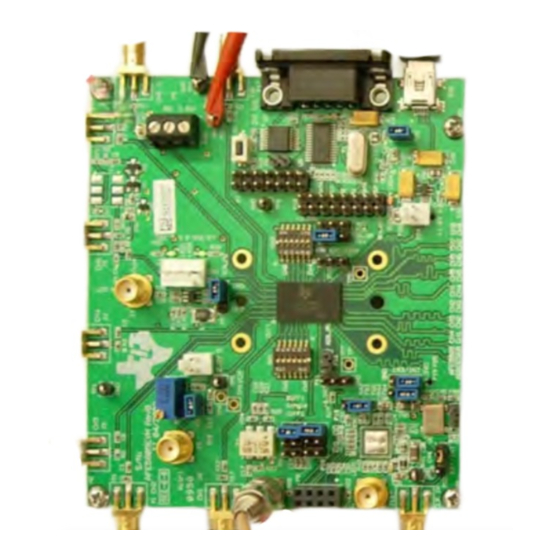
I/O and Power Connectors Pin A1 of the AFE5805 is marked by a white dot on its package as well as a white dot on the board. The positions and functions of the AFE5805EVM connectors are discussed in this section. CW Out... -
Page 5: Jumpers And Setup
Jumpers and Setup In the following detailed description, the board has been set to default mode (see Figure Figure 3. Locations of Jumpers, JTAG, and Switches on the AFE5805EVM SLOU222C – March 2008 – Revised March 2015 AFE5805EVM Submit Documentation Feedback... -
Page 6: Default Setup For Jumpers
Board Configuration www.ti.com Figure 4. Default Setup for Jumpers AFE5805EVM SLOU222C – March 2008 – Revised March 2015 Submit Documentation Feedback Copyright © 2008–2015, Texas Instruments Incorporated... -
Page 7: Test Points
TP6: GND • TP7: Test point, TI internal only • TP8: +5 V • TP9: CM • TP10:GND • TP11: -5 V SLOU222C – March 2008 – Revised March 2015 AFE5805EVM Submit Documentation Feedback Copyright © 2008–2015, Texas Instruments Incorporated... -
Page 8: Board Operation
The personal computer (PC) should recognize the EVM after software installation. To launch the software after successful installation, click: Start Menu → All Programs → Texas Instruments → AFE5805EVM USB SPI → AFE5805EVM USB SPI Three different modes are shown in Figure... -
Page 9: Afe5805Evm Usb Spi Interface For Cw Mode
Board Operation www.ti.com Figure 6. AFE5805EVM USB SPI Interface for CW Mode SLOU222C – March 2008 – Revised March 2015 AFE5805EVM Submit Documentation Feedback Copyright © 2008–2015, Texas Instruments Incorporated... -
Page 10: Hardware Setup
Figure 7. AFE5805EVM USB SPI Interface for ADC Setup Hardware Setup When the AFE5805EVM is powered on in the default mode, the AFE5805 is set as described in Table Table 1. AFE5805EVM Default Settings When Powered On TGC mode... -
Page 11: Clock Selection
ADSDESER FCLK LCLK For example, when an analog signal is present on CH1 of the AFE5805EVM, the corresponding 12-bit digital output can be seen on CH4 of the ADSDeSER-50EVM. Clock Selection The AFE5805 can be clocked through a transformer-based differential clock, single-ended clock, or future... -
Page 12: Data Analysis
HP8644s are required for generating an ADC clock and analog signal. For most users, this may be infeasible. Data analysis based on windowing is a more suitable approach. Schematics and Layout This section provides the schematics, the AFE5805EVM board layout, and the bill of materials. Schematics The schematics appear at the end of the document. -
Page 13: Top Layer, Signal
Schematics and Layout www.ti.com Figure 10. Top Layer, Signal SLOU222C – March 2008 – Revised March 2015 AFE5805EVM Submit Documentation Feedback Copyright © 2008–2015, Texas Instruments Incorporated... -
Page 14: Inner Layer 1, Ground
Schematics and Layout www.ti.com Figure 11. Inner Layer 1, Ground AFE5805EVM SLOU222C – March 2008 – Revised March 2015 Submit Documentation Feedback Copyright © 2008–2015, Texas Instruments Incorporated... -
Page 15: Inner Layer 2, Signal
Schematics and Layout www.ti.com Figure 12. Inner Layer 2, Signal SLOU222C – March 2008 – Revised March 2015 AFE5805EVM Submit Documentation Feedback Copyright © 2008–2015, Texas Instruments Incorporated... -
Page 16: Inner Layer 3, Power
Schematics and Layout www.ti.com Figure 13. Inner Layer 3, Power AFE5805EVM SLOU222C – March 2008 – Revised March 2015 Submit Documentation Feedback Copyright © 2008–2015, Texas Instruments Incorporated... -
Page 17: Inner Layer 4, Ground
Schematics and Layout www.ti.com Figure 14. Inner Layer 4, Ground SLOU222C – March 2008 – Revised March 2015 AFE5805EVM Submit Documentation Feedback Copyright © 2008–2015, Texas Instruments Incorporated... -
Page 18: Bottom Layer, Signal
Schematics and Layout www.ti.com Figure 15. Bottom Layer, Signal AFE5805EVM SLOU222C – March 2008 – Revised March 2015 Submit Documentation Feedback Copyright © 2008–2015, Texas Instruments Incorporated... - Page 19 Schematics and Layout www.ti.com Figure 16. Top Silk Screen Layer SLOU222C – March 2008 – Revised March 2015 AFE5805EVM Submit Documentation Feedback Copyright © 2008–2015, Texas Instruments Incorporated...
- Page 20 Schematics and Layout www.ti.com Figure 17. Bottom Silk Screen Layer AFE5805EVM SLOU222C – March 2008 – Revised March 2015 Submit Documentation Feedback Copyright © 2008–2015, Texas Instruments Incorporated...
-
Page 21: Bill Of Materials
P6, P10 HEADER,THU,6P,2x3,MALE,DUAL ROW,100LS,200TL SAMTEC TSW-107-07-G-D HEADER,THU,14P,2x7,MALE,DUAL ROW,100LS,100TL SAMTEC TSW-108-07-G-D HEADER,THU,16P,2x8,MALE,DUAL ROW,100LS,100TL(UNINSTALLED) TYCO 103321-2 P3, P8, P12, P21, P23 HEADER W/SHUNT,2P,100LS ELECTRONICS SLOU222C – March 2008 – Revised March 2015 AFE5805EVM Submit Documentation Feedback Copyright © 2008–2015, Texas Instruments Incorporated... - Page 22 5006 TP1, TP2, TP5, TP6, TP10 TESTPOINT,THU,COMPACT,0.125LS,130TL, BLACK ELECTRONICS KEYSTONE 5006(UN) TP3, TP4, TP7, TP9 UNINSTALLED PART ( TEST POINT ) ELECTRONICS AFE5805EVM SLOU222C – March 2008 – Revised March 2015 Submit Documentation Feedback Copyright © 2008–2015, Texas Instruments Incorporated...
- Page 23 2: ITEM 30, 32, and 34 ARE STRAIGHT SINGLE ROW 36 POSITION HEADER QUANTITY OF STRIPS WILL CHANGE WITH NUMBER OF BOARDS BEING BUILT. SLOU222C – March 2008 – Revised March 2015 AFE5805EVM Submit Documentation Feedback Copyright © 2008–2015, Texas Instruments Incorporated...
-
Page 24: Typical Performance
Typical Performance This section provides some typical performance characteristics of the AFE5805EVM to assist users in verifying their setup. After analysis of the data file acquired by a logic analyzer, the SNR of the AFE5805 should be better than 59 dB when the PGA is set to 30 dB and Vctnl is set as 1 V. - Page 25 19, the settings are PGA=30 dB, Vcntl=1 V, and LPF=15 MHz. Figure 19. Typical Performance of AFE5805 With (a) HP8644 and (b) Onboard 40-MHz Clock SLOU222C – March 2008 – Revised March 2015 AFE5805EVM Submit Documentation Feedback Copyright © 2008–2015, Texas Instruments Incorporated...
-
Page 26: Appendix Atsw1400 For Evaluating Afe5805
This application note demonstrates typical steps of evaluating the AFE5805 using the TSW1400EVM and its associated data. Step 1: Hardware Setup Figure 20. Connection between TSW1400EVM and AFE5805 TSW1400 for Evaluating AFE5805 SLOU222C – March 2008 – Revised March 2015 Submit Documentation Feedback Copyright © 2008–2015, Texas Instruments Incorporated... - Page 27 Step 1: Hardware Setup www.ti.com Figure 21. Connection of the Instruments SLOU222C – March 2008 – Revised March 2015 TSW1400 for Evaluating AFE5805 Submit Documentation Feedback Copyright © 2008–2015, Texas Instruments Incorporated...
- Page 28 Set Amplitude of the signal generator to about -3dBm – -33dBm Set the Frequency of the Clock Generator to 40MHz. Set Amplitude of the Clock Generator to 13 dBm. TSW1400 for Evaluating AFE5805 SLOU222C – March 2008 – Revised March 2015 Submit Documentation Feedback Copyright © 2008–2015, Texas Instruments Incorporated...
- Page 29 Following the steps in the orders as indicated in the following figure to set the test condition. Figure 23. User Interface: Step-by-Step setup After the above steps are complete; the following figure appears. SLOU222C – March 2008 – Revised March 2015 TSW1400 for Evaluating AFE5805 Submit Documentation Feedback Copyright © 2008–2015, Texas Instruments Incorporated...
- Page 30 For noisy conditions, the amplitude of the signal may be too large; continue decrement the signal generator amplitude by 1dBm until the desired results are achieved. TSW1400 for Evaluating AFE5805 SLOU222C – March 2008 – Revised March 2015 Submit Documentation Feedback Copyright © 2008–2015, Texas Instruments Incorporated...
- Page 31 Launch TSW1400 GUI www.ti.com A.3.1 Single Tone FFT Data Figure 25. Typical Performance of AFE5805 SLOU222C – March 2008 – Revised March 2015 TSW1400 for Evaluating AFE5805 Submit Documentation Feedback Copyright © 2008–2015, Texas Instruments Incorporated...
- Page 32 Single Tone FFT Data -100 -125 5000000 10000000 15000000 20000000 Frequency Figure 26. Single Tone FFT Test Data Plot in EXCELL TSW1400 for Evaluating AFE5805 SLOU222C – March 2008 – Revised March 2015 Submit Documentation Feedback Copyright © 2008–2015, Texas Instruments Incorporated...
- Page 33 3. The whole picture includes the setup parameter are saved. Figure 27. Single Tone FFT Test Data Saved as filename.jpeg SLOU222C – March 2008 – Revised March 2015 TSW1400 for Evaluating AFE5805 Submit Documentation Feedback Copyright © 2008–2015, Texas Instruments Incorporated...
- Page 34 The signal generator is still required for the signal source. Figure 28. Typical Performance of AFE5805 in Non-Coherent Case TSW1400 for Evaluating AFE5805 SLOU222C – March 2008 – Revised March 2015 Submit Documentation Feedback Copyright © 2008–2015, Texas Instruments Incorporated...
- Page 35 Figure 29. User Interface: Time Domain Format SLOU222C – March 2008 – Revised March 2015 TSW1400 for Evaluating AFE5805 Submit Documentation Feedback Copyright © 2008–2015, Texas Instruments Incorporated...
-
Page 36: Appendix B High Speed Data Converter Pro (Hsdcpro) Gui Installation
Leave the destination directories as the default location, for the TSW1400GUI installation and press the NEXT button as shown in Figure High Speed Data Converter Pro (HSDCPro) GUI Installation SLOU222C – March 2008 – Revised March 2015 Submit Documentation Feedback Copyright © 2008–2015, Texas Instruments Incorporated... - Page 37 Appendix B www.ti.com Figure 31. HSDCPro Install (Install Directory) • Read the License Agreement from Texas Instruments and select I accept the License Agreement and press the Next button as shown in Figure SLOU222C – March 2008 – Revised March 2015...
- Page 38 Read the License Agreement from National Instruments and select I accept the License Agreement and press the Next button as shown in Figure High Speed Data Converter Pro (HSDCPro) GUI Installation SLOU222C – March 2008 – Revised March 2015 Submit Documentation Feedback Copyright © 2008–2015, Texas Instruments Incorporated...
- Page 39 Figure 33. HSDCPro Install (NI License Agreement) • Press the Next button as shown in Figure SLOU222C – March 2008 – Revised March 2015 High Speed Data Converter Pro (HSDCPro) GUI Installation Submit Documentation Feedback Copyright © 2008–2015, Texas Instruments Incorporated...
- Page 40 The window shown in Figure 35 should appear indicating that the installation is in progress. High Speed Data Converter Pro (HSDCPro) GUI Installation SLOU222C – March 2008 – Revised March 2015 Submit Documentation Feedback Copyright © 2008–2015, Texas Instruments Incorporated...
- Page 41 • The window shown in Figure 36 appears indicating Installation Complete. Press the Next button. SLOU222C – March 2008 – Revised March 2015 High Speed Data Converter Pro (HSDCPro) GUI Installation Submit Documentation Feedback Copyright © 2008–2015, Texas Instruments Incorporated...
- Page 42 Figure 36. HSDCPro Install (Installation Complete) • The window shown in Figure 37 appears briefly to complete the process. High Speed Data Converter Pro (HSDCPro) GUI Installation SLOU222C – March 2008 – Revised March 2015 Submit Documentation Feedback Copyright © 2008–2015, Texas Instruments Incorporated...
- Page 43 National Instruments MCR Installer. If requested, hit the Restart button to complete the installation. Figure 38. HSDCPro Install SLOU222C – March 2008 – Revised March 2015 High Speed Data Converter Pro (HSDCPro) GUI Installation Submit Documentation Feedback Copyright © 2008–2015, Texas Instruments Incorporated...
- Page 46 Added Appendix B: High Speed Data Converter Pro (HSDCPro) GUI Installation. NOTE: Page numbers for previous revisions may differ from page numbers in the current version. Revision History SLOU222C – March 2008 – Revised March 2015 Submit Documentation Feedback Copyright © 2008–2015, Texas Instruments Incorporated...
- Page 47 STANDARD TERMS AND CONDITIONS FOR EVALUATION MODULES Delivery: TI delivers TI evaluation boards, kits, or modules, including any accompanying demonstration software, components, or documentation (collectively, an “EVM” or “EVMs”) to the User (“User”) in accordance with the terms and conditions set forth herein. Acceptance of the EVM is expressly subject to the following terms and conditions.
- Page 48 FCC Interference Statement for Class B EVM devices NOTE: This equipment has been tested and found to comply with the limits for a Class B digital device, pursuant to part 15 of the FCC Rules. These limits are designed to provide reasonable protection against harmful interference in a residential installation.
- Page 49 【無線電波を送信する製品の開発キットをお使いになる際の注意事項】 本開発キットは技術基準適合証明を受けておりません。 本製品のご使用に際しては、電波法遵守のため、以下のいずれかの措置を取っていただく必要がありますのでご注意ください。 1. 電波法施行規則第6条第1項第1号に基づく平成18年3月28日総務省告示第173号で定められた電波暗室等の試験設備でご使用 いただく。 2. 実験局の免許を取得後ご使用いただく。 3. 技術基準適合証明を取得後ご使用いただく。 なお、本製品は、上記の「ご使用にあたっての注意」を譲渡先、移転先に通知しない限り、譲渡、移転できないものとします。 上記を遵守頂けない場合は、電波法の罰則が適用される可能性があることをご留意ください。 日本テキサス・インスツルメンツ株式会社 東京都新宿区西新宿6丁目24番1号 西新宿三井ビル 3.3.3 Notice for EVMs for Power Line Communication: Please see http://www.tij.co.jp/lsds/ti_ja/general/eStore/notice_02.page 電力線搬送波通信についての開発キットをお使いになる際の注意事項については、次のところをご覧くださ い。http://www.tij.co.jp/lsds/ti_ja/general/eStore/notice_02.page SPACER EVM Use Restrictions and Warnings: 4.1 EVMS ARE NOT FOR USE IN FUNCTIONAL SAFETY AND/OR SAFETY CRITICAL EVALUATIONS, INCLUDING BUT NOT LIMITED TO EVALUATIONS OF LIFE SUPPORT APPLICATIONS.
- Page 50 Notwithstanding the foregoing, any judgment may be enforced in any United States or foreign court, and TI may seek injunctive relief in any United States or foreign court. Mailing Address: Texas Instruments, Post Office Box 655303, Dallas, Texas 75265 Copyright © 2015, Texas Instruments Incorporated...
- Page 51 IMPORTANT NOTICE Texas Instruments Incorporated and its subsidiaries (TI) reserve the right to make corrections, enhancements, improvements and other changes to its semiconductor products and services per JESD46, latest issue, and to discontinue any product or service per JESD48, latest issue.
- Page 52 Mouser Electronics Authorized Distributor Click to View Pricing, Inventory, Delivery & Lifecycle Information: Texas Instruments AFE5805EVM...
Need help?
Do you have a question about the AFE5805EVM and is the answer not in the manual?
Questions and answers