Table of Contents
Advertisement
www.ti.com
User's Guide
AFE4500 EVM User Guide
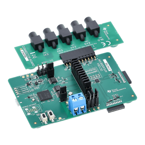
This user guide describes the operation of the AFE4500 EVM demonstration kit. This demonstration kit is
an evaluation module for the AFE4500 device. The AFE4500 is a fully-Integrated AFE for Wearable Optical
Heart-Rate Monitoring, SpO2, ECG and BIA. The EVM is intended for evaluation of the AFE features. This
document also describes the steps for generating the AFE4500 register configuration files using the provided
Excel tool for different operating conditions.
Evaluation.......................................................................................................................................................2
Contents...............................................................................................................................................2
1.3 Install the USB driver.........................................................................................................................................................
Upgrade.....................................................................................................................................................4
1.5 Setup the Hardware...........................................................................................................................................................
Software..........................................................................................................................................................................9
2.1 Import AFE Register Configuration..................................................................................................................................
2.2 Capturing the AFE data and Plotting................................................................................................................................
3 AFE4500 EVM Hardware .....................................................................................................................................................
3.1 Power Supply...................................................................................................................................................................
3.2 Clock................................................................................................................................................................................
3.3 Accessing AFE4500 Digital Signals ................................................................................................................................
3.5 To Interface an MCU on a Different Board with the AFE of EVM.....................................................................................
Interface...................................................................................................................................................................19
3.7 On-Board Key Interface...................................................................................................................................................
3.8 Visual Indication...............................................................................................................................................................
Interface..............................................................................................................................................................20
4.1 Micro-USB Connector......................................................................................................................................................
Connector.....................................................................................................................................................20
5.1 PPG Configuration...........................................................................................................................................................
5.2
ECG-Configuration...........................................................................................................................................................24
5.3
BIA-Configuration.............................................................................................................................................................25
5.4 Mix configuration..............................................................................................................................................................
6.1 Adding a new script file....................................................................................................................................................
6.2 Writing a script to configure the device and the capture data..........................................................................................
A Hardware Reference............................................................................................................................................................
A.1 AFE4500 Schematics......................................................................................................................................................
Recommendations.......................................................................................................................................34
A.3 AFE4500 Bill of Materials................................................................................................................................................
History...................................................................................................................................................................46
Trademarks
All trademarks are the property of their respective owners.
SBAU370 - APRIL 2021
Submit Document Feedback
Table of Contents
Software............................................................................................................................3
............................................................................................................................................22
Excel...................................................................................................................................23
Files................................................................................................................................................27
Script.......................................................................................................................................28
Copyright © 2021 Texas Instruments Incorporated
ABSTRACT
Board......................................................................18
Table of Contents
3
5
10
11
16
16
17
17
18
19
19
20
23
26
28
28
31
31
40
AFE4500 EVM User Guide
1
Advertisement
Table of Contents

Related Manuals for Texas Instruments AFE4500EVM


Summary of Contents for Texas Instruments AFE4500EVM
-
Page 1: Table Of Contents
A.1 AFE4500 Schematics..............................A.2 PCB Layout Recommendations............................34 A.3 AFE4500 Bill of Materials..............................B Revision History...................................46 Trademarks All trademarks are the property of their respective owners. SBAU370 – APRIL 2021 AFE4500 EVM User Guide Submit Document Feedback Copyright © 2021 Texas Instruments Incorporated... -
Page 2: Afe4500 Evm Evaluation
Table 1-1. EVM software and other useful files in MSS folder File Description Bio-Sensing_Installer_Vx.exe Base Installer for GUI AFE4500EVM_Installer_Vx.exe Project specific installer for AFE4500EVM Register-Config_Vx.zip Contains latest Excel based register generation tool BSL_Vx.zip Contains latest compiled firmware as well as a utility to load the firmware into EVM USB_Driver_Vx.zip... -
Page 3: Install The Pc Application Evm Software
1-2) before installing the new driver. Figure 1-2. Uninstalling the driver of previous generation AFE44xx/AFE49xx EVM After deleting the old driver, if AFE4500EVM doesn’t get detected as 2 USB COM port then follow the step given below to install the new driver. -
Page 4: Evm Firmware Upgrade
1-3(a) shows the firmware loader application with the appropriate firmware selected. The firmware is provided along with EVM software and will be at the below location. Version number could differ. C:\Program Files\Texas Instruments\Bio- Sensing\AFE4500EVM\EVM Firmware\AFE4500 V1.1.0.txt 3. Press the switch named BSL on the EVM while plugging in the micro-USB interface cable on the EVM. -
Page 5: Setup The Hardware
Figure 1-4. Figure 1-4. Connecting USB cable to AFE4500EVM 3. Connect the PPG sensor module to the EVM’s J3 connector using 10-pin to 10-pin sensor board extension cable. Make sure that the sensor module is connected in the correct orientation, that is the pin 1 should line... - Page 6 Figure 1-6, connect the connector board with ECG connector to the J2 Connector of AFE4500EVM and the connect the ECG Cables provided to the ECG connectors on the connector board. Figure 1-6. Connecting the ECG cables to the EVM 5. Place the sensor side of the PPG sensor board on the wrist and tie it snugly.
- Page 7 Figure 1-7. PPG sensor board and ECG cable interaction to the hand for acquiring PPG and ECG signals 6. Open the EVM software by running Bio-Sensing.exe. Figure 1-8. Opening Bio-Sensing.exe 7. From project specific profile (i.e. AFE4500EVM >> GUI) go to devInit.py script file and run (Short cut for running the script: F5) as shown in Figure 1-9, which loads the default EVM configuration.
- Page 8 AFE4500 EVM Evaluation www.ti.com Figure 1-9. Running the EVM software. AFE4500 EVM User Guide SBAU370 – APRIL 2021 Submit Document Feedback Copyright © 2021 Texas Instruments Incorporated...
-
Page 9: Evm Software
6. BIA: This page has controls that helps in loading BIA configuration and BIA calibration settings. SBAU370 – APRIL 2021 AFE4500 EVM User Guide Submit Document Feedback Copyright © 2021 Texas Instruments Incorporated... -
Page 10: Import Afe Register Configuration
Wait for the loading to complete and reach 100%. After loading is completed, navigate to CAPTURE page. Figure 2-4. Loading configuration file generated using the configuration tool AFE4500 EVM User Guide SBAU370 – APRIL 2021 Submit Document Feedback Copyright © 2021 Texas Instruments Incorporated... -
Page 11: Capturing The Afe Data And Plotting
Check “APPLY FILTERING” if signal needs to be filtered using software filters. • Select the Plot1, Plot2, Plot3 or Plot4 in which the signal is to be plotted. Click Add Plot. SBAU370 – APRIL 2021 AFE4500 EVM User Guide Submit Document Feedback Copyright © 2021 Texas Instruments Incorporated... - Page 12 Characteristics of each filter such as filter order and cutoff frequency can be tweaked in “FILTER SETTINGS” tab. Each filer can be individually enabled or disabled. AFE4500 EVM User Guide SBAU370 – APRIL 2021 Submit Document Feedback Copyright © 2021 Texas Instruments Incorporated...
- Page 13 5. BIA: For measuring the Body Impedance, all useful controls are given in this tab. • Plug-In board for demonstration of BIA as shown in Figure 2-10 SBAU370 – APRIL 2021 AFE4500 EVM User Guide Submit Document Feedback Copyright © 2021 Texas Instruments Incorporated...
- Page 14 Figure 2-11. Loading closed electrode configuration • Select the DATA that need to be available in the data to plot drop down as shown in Figure 2-12 AFE4500 EVM User Guide SBAU370 – APRIL 2021 Submit Document Feedback Copyright © 2021 Texas Instruments Incorporated...
- Page 15 Select the signal source to be plotted and start capture as shown in Figure 2-13. Figure 2-13. Selecting data to be plotted and stating capture SBAU370 – APRIL 2021 AFE4500 EVM User Guide Submit Document Feedback Copyright © 2021 Texas Instruments Incorporated...
-
Page 16: Afe4500 Evm Hardware
3 AFE4500 EVM Hardware CAUTION Many of the components on the AFE4500EVM are susceptible to damage by electrostatic discharge (ESD). Customers are advised to observe proper ESD handling precautions when unpacking and handling the EVM, including the use of a grounded wrist strap, bootstraps, or mats at an approved ESD workstation. -
Page 17: Clock
The digital signals of the AFE that interface with the MSP430 can be accessed through the test 24 pin dual row connector. Figure 3-2. Digital signals SBAU370 – APRIL 2021 AFE4500 EVM User Guide Submit Document Feedback Copyright © 2021 Texas Instruments Incorporated... -
Page 18: Interfacing The Msp430 On The Evm To An Afe4500 On A Different Board
ADC_RDY J1-AFE_ADC_RDY ADC_RDY RESETZ J1- AFE_RESET RESETZ J1- AFE_CLK LDO_BYP J1- AFE_LDO_BYP LDO_BYP • Share the GND signal between the module and EVM AFE4500 EVM User Guide SBAU370 – APRIL 2021 Submit Document Feedback Copyright © 2021 Texas Instruments Incorporated... -
Page 19: Usb Interface
D21 ON: USB is not enumerated. This can happen if the EVM is only getting power from the USB and not able to communicate • D23 ON: AFE4500 registers are getting written by MCU. • D22 ON: MCU is reading the AFE4500 registers. SBAU370 – APRIL 2021 AFE4500 EVM User Guide Submit Document Feedback Copyright © 2021 Texas Instruments Incorporated... -
Page 20: Connector Interface
Table 4-2 . EVM uses two SFH7072 sensor boards. The connections of the sensor board to the AFE are also listed in Table 4-3 AFE4500 EVM User Guide SBAU370 – APRIL 2021 Submit Document Feedback Copyright © 2021 Texas Instruments Incorporated... - Page 21 PD2 (INP2-INM2) PD1 (INP1-INM1) Green LED1 Green LED2 Red LED IR LED Green (IR Cut) PD RED/IR (Broadband) PD PD3 (INP3-INM3) PD4 (INP4-INM4) SBAU370 – APRIL 2021 AFE4500 EVM User Guide Submit Document Feedback Copyright © 2021 Texas Instruments Incorporated...
-
Page 22: 10-Pin Bia+Ecg Connector
10-pin BIA+ECG connector pinout. The BIA and ECG demonstration boards need to be interface to this connector. Figure 4-3. 10 pin PPG sensor board interface connector pinout AFE4500 EVM User Guide SBAU370 – APRIL 2021 Submit Document Feedback Copyright © 2021 Texas Instruments Incorporated... -
Page 23: Afe4500 Register Generation Excel
5 AFE4500 Register Generation Excel The AFE4500_Register_Generation_v*.xlsm will be given by TI. This configuration file will be in the EVM software installation directory. Default file location: C:\Program Files\Texas Instruments\Bio-Sensing\AFE4500EVM\Register config\ AFE4500_Register_Generation_v*.xlsm By default the EVM ships in LDO enable mode with following configuration •... -
Page 24: Ecg-Configuration
Settings related to ECG can be configured in the worksheet called ECG-Configuration. ECG parameters such as INA Gain, Electrode configuration, Lead detection and saturation detection can be configured in this worksheet. AFE4500 EVM User Guide SBAU370 – APRIL 2021 Submit Document Feedback Copyright © 2021 Texas Instruments Incorporated... -
Page 25: Bia-Configuration
Figure 5-3. ECG configuration 5.3 BIA-Configuration Register configuration tool configured for BIA operation is provided along with the installer. The pre- configured high frequency BIA configuration tool is placed at “C:\Program Files\Texas Instruments\Bio- SBAU370 – APRIL 2021 AFE4500 EVM User Guide Submit Document Feedback Copyright ©... -
Page 26: Mix Configuration
AFE4500 Register Generation Excel www.ti.com Sensing\AFE4500EVM\Register Config\BIA HF Closed Electrode\”. BIA related settings can be configured in “BIA_Config” worksheet. “BIACalibConfigs” worksheet contains the dynamic switch positions. Figure 5-4. BIA Configuration 5.4 Mix configuration If the acquisition mode selected is MIX1/MIX2, the “MIX_Config” worksheet needs to be configured. The PRF, time slot related settings, decimation filter settings are available in this worksheet. -
Page 27: Generate The Output Files
AFE4500_Settings_mcu.cfg: Register configuration in {address, data} format • AFE4500_FIFO_SEQ.cfg: Data sequence in the FIFO • AFE4500_DATARATE.cfg: Output data rate for each type of output data. SBAU370 – APRIL 2021 AFE4500 EVM User Guide Submit Document Feedback Copyright © 2021 Texas Instruments Incorporated... -
Page 28: Modifying Or Creating Own Script
This section details on how to create a custom script or modify any of the existing script to match the expected configurations. 6.1 Adding a new script file Click on the required profile (AFE4500EVM➜GUI) in which the script file needs to be added. • Right click the profile under which the new script file should be added. - Page 29 While doing a raw write using the AFE.writeReg function, the bitfield variables doesn’t get updated. In-order to update the bitfield names, call function workSpaceWindow.updateRegisterSettingsTab() SBAU370 – APRIL 2021 AFE4500 EVM User Guide Submit Document Feedback Copyright © 2021 Texas Instruments Incorporated...
- Page 30 6.2.4 Starting and stopping capture from script Below script shows capturing the data for 10 seconds, stopping it and then accessing the captured data. AFE4500 EVM User Guide SBAU370 – APRIL 2021 Submit Document Feedback Copyright © 2021 Texas Instruments Incorporated...
-
Page 31: A Hardware Reference
Figure A-1 through Figure A-6 show the EVM schematics. Figure A-1. AFE4500 Schematic 1 of 6 Figure A-2. AFE4500 Schematic 2 of 6 SBAU370 – APRIL 2021 AFE4500 EVM User Guide Submit Document Feedback Copyright © 2021 Texas Instruments Incorporated... - Page 32 Hardware Reference www.ti.com Figure A-3. AFE4500 Schematic 3 of 6 Figure A-4. AFE4500 Schematic 4 of 6 AFE4500 EVM User Guide SBAU370 – APRIL 2021 Submit Document Feedback Copyright © 2021 Texas Instruments Incorporated...
- Page 33 Hardware Reference Figure A-5. AFE4500 Schematic 5 of 6 Figure A-6. AFE4500 Schematic 6 of 6 SBAU370 – APRIL 2021 AFE4500 EVM User Guide Submit Document Feedback Copyright © 2021 Texas Instruments Incorporated...
-
Page 34: Pcb Layout Recommendations
A.2 PCB Layout Recommendations Figure A-7 through Figure A-12 show the PCB Layout Recommendations. Figure A-7. AFE4500 PCB Layout Recommendation 1 of 11 AFE4500 EVM User Guide SBAU370 – APRIL 2021 Submit Document Feedback Copyright © 2021 Texas Instruments Incorporated... - Page 35 Hardware Reference Figure A-8. AFE4500 PCB Layout Recommendation 2 of 11 SBAU370 – APRIL 2021 AFE4500 EVM User Guide Submit Document Feedback Copyright © 2021 Texas Instruments Incorporated...
- Page 36 Hardware Reference www.ti.com Figure A-9. AFE4500 PCB Layout Recommendation 3 of 11 AFE4500 EVM User Guide SBAU370 – APRIL 2021 Submit Document Feedback Copyright © 2021 Texas Instruments Incorporated...
- Page 37 Hardware Reference Figure A-10. AFE4500 PCB Layout Recommendation 4 of 11 SBAU370 – APRIL 2021 AFE4500 EVM User Guide Submit Document Feedback Copyright © 2021 Texas Instruments Incorporated...
- Page 38 Hardware Reference www.ti.com Figure A-11. AFE4500 PCB Layout Recommendation 5 of 11 AFE4500 EVM User Guide SBAU370 – APRIL 2021 Submit Document Feedback Copyright © 2021 Texas Instruments Incorporated...
- Page 39 Hardware Reference Figure A-12. AFE4500 PCB Layout Recommendation 6 of 11 SBAU370 – APRIL 2021 AFE4500 EVM User Guide Submit Document Feedback Copyright © 2021 Texas Instruments Incorporated...
-
Page 40: Afe4500 Bill Of Materials
C0603X5R1E102K 10%, X5R, 0201 030BA C54, C55, C57, 10pF CAP, CERM, 10 pF, 25 V, +/- 5%, 0201 GJM0335C1E100J MuRata C0G/NP0, 0201 B01D AFE4500 EVM User Guide SBAU370 – APRIL 2021 Submit Document Feedback Copyright © 2021 Texas Instruments Incorporated... - Page 41 Receptacle, 2.54mm, 613010143121 Wurth Elektronik Gold, R/A, TH 10x1, TH J302, J303, J304, Touchproof Jack, R/A, TH Touchproof Jack, R/A, 8R004182801F PlasticsOne J305, J306 SBAU370 – APRIL 2021 AFE4500 EVM User Guide Submit Document Feedback Copyright © 2021 Texas Instruments Incorporated...
- Page 42 1.40k RES, 1.40 k, 1%, 0.05 W, 0201 0201 RC0201FR-071K4 Yageo America 33.0 RES, 33.0, 1%, 0.05 W, 0201 0201 RC0201FR-0733R Yageo America AFE4500 EVM User Guide SBAU370 – APRIL 2021 Submit Document Feedback Copyright © 2021 Texas Instruments Incorporated...
- Page 43 DPW0005A (X2SON-5) 500mA Low Dropout CMOS NGG0006A LP38693SD-5.0/ Texas Instruments Linear Regulators Stable with NOPB Ceramic Output Capacitors, 6- pin LLP, Pb-Free, 1000 Reel SBAU370 – APRIL 2021 AFE4500 EVM User Guide Submit Document Feedback Copyright © 2021 Texas Instruments Incorporated...
- Page 44 C211, C212 C102, C107, C110, 100pF CAP, CERM, 100 pF, 50 V, +/- 0402 04025A101FAT2A C113, C202, C207, 1%, C0G/NP0, 0402 C210, C213 AFE4500 EVM User Guide SBAU370 – APRIL 2021 Submit Document Feedback Copyright © 2021 Texas Instruments Incorporated...
- Page 45 TP7, TP8 Note Unless otherwise noted in the Alternate PartNumber and/or Alternate Manufacturer columns, all parts may be substituted with equivalents. SBAU370 – APRIL 2021 AFE4500 EVM User Guide Submit Document Feedback Copyright © 2021 Texas Instruments Incorporated...
-
Page 46: B Revision History
B Revision History NOTE: Page numbers for previous revisions may differ from page numbers in the current version. DATE REVISION NOTES April 2021 Initial Release AFE4500 EVM User Guide SBAU370 – APRIL 2021 Submit Document Feedback Copyright © 2021 Texas Instruments Incorporated... - Page 47 STANDARD TERMS FOR EVALUATION MODULES Delivery: TI delivers TI evaluation boards, kits, or modules, including any accompanying demonstration software, components, and/or documentation which may be provided together or separately (collectively, an “EVM” or “EVMs”) to the User (“User”) in accordance with the terms set forth herein.
- Page 48 www.ti.com Regulatory Notices: 3.1 United States 3.1.1 Notice applicable to EVMs not FCC-Approved: FCC NOTICE: This kit is designed to allow product developers to evaluate electronic components, circuitry, or software associated with the kit to determine whether to incorporate such items in a finished product and software developers to write software applications for use with the end product.
- Page 49 www.ti.com Concernant les EVMs avec antennes détachables Conformément à la réglementation d'Industrie Canada, le présent émetteur radio peut fonctionner avec une antenne d'un type et d'un gain maximal (ou inférieur) approuvé pour l'émetteur par Industrie Canada. Dans le but de réduire les risques de brouillage radioélectrique à...
- Page 50 www.ti.com EVM Use Restrictions and Warnings: 4.1 EVMS ARE NOT FOR USE IN FUNCTIONAL SAFETY AND/OR SAFETY CRITICAL EVALUATIONS, INCLUDING BUT NOT LIMITED TO EVALUATIONS OF LIFE SUPPORT APPLICATIONS. 4.2 User must read and apply the user guide and other available documentation provided by TI regarding the EVM prior to handling or using the EVM, including without limitation any warning or restriction notices.
- Page 51 Notwithstanding the foregoing, any judgment may be enforced in any United States or foreign court, and TI may seek injunctive relief in any United States or foreign court. Mailing Address: Texas Instruments, Post Office Box 655303, Dallas, Texas 75265 Copyright © 2019, Texas Instruments Incorporated...
- Page 52 TI products. TI’s provision of these resources does not expand or otherwise alter TI’s applicable warranties or warranty disclaimers for TI products.IMPORTANT NOTICE Mailing Address: Texas Instruments, Post Office Box 655303, Dallas, Texas 75265 Copyright © 2021, Texas Instruments Incorporated...
Need help?
Do you have a question about the AFE4500EVM and is the answer not in the manual?
Questions and answers