Table of Contents
Advertisement
Quick Links
www.ti.com
User's Guide
AFE539A4EVM
This user's guide describes the characteristics, operation, and use of the AFE539A4EVM evaluation module
(EVM). This EVM is designed to evaluate the performance of the AFE539A4. Throughout this document, the
terms evaluation board, evaluation module, and EVM are synonymous with the AFE539A4EVM. This document
includes a schematic, reference printed-circuit board (PCB) layouts, and a complete bill of materials.
SLAU859 – JULY 2021
Submit Document Feedback
ABSTRACT
Copyright © 2021 Texas Instruments Incorporated
AFE539A4EVM
1
Advertisement
Table of Contents

Subscribe to Our Youtube Channel
Related Manuals for Texas Instruments AFE539A4EVM


Summary of Contents for Texas Instruments AFE539A4EVM
- Page 1 AFE539A4EVM ABSTRACT This user’s guide describes the characteristics, operation, and use of the AFE539A4EVM evaluation module (EVM). This EVM is designed to evaluate the performance of the AFE539A4. Throughout this document, the terms evaluation board, evaluation module, and EVM are synonymous with the AFE539A4EVM. This document includes a schematic, reference printed-circuit board (PCB) layouts, and a complete bill of materials.
-
Page 2: Table Of Contents
Figure 2-3. TI Cloud Agent Installation............................Figure 2-4. Hardware Setup................................ Figure 2-5. Hardware Setup Guidelines............................Figure 3-1. BOOSTXL-DAC-PORT Hardware Block Diagram.....................9 Figure 3-2. AFE539A4EVM Hardware Simplified Schematic....................Figure 3-3. AFE539A4EVM GUI Location..........................Figure 3-4. AFE539A4EVM GUI Connection Detection......................Figure 3-5. Home Page................................Figure 3-6. Setup Page................................16... - Page 3 Trademarks Trademarks LaunchPad ™ is a trademark of Texas Instruments. Windows ™ is a trademark of Microsoft Corporation. macOS ™ is a trademark of Apple Inc. Linux ™ is a trademark of Linus Torvalds. All trademarks are the property of their respective owners.
-
Page 4: Overview
Table 1-1 details the contents of the EVM kit. Contact the nearest TI Product Information Center if any component is missing. Make sure to verify the latest versions of the related software at the Texas Instruments website, www.ti.com. Table 1-1. Contents of AFE539A4EVM Kit... -
Page 5: System Setup
AFE539A4EVM software installer executable. When the AFE539A4EVM software is launched, an installation dialog window opens and prompts the user to select an installation directory. If left unchanged, the software location defaults to C:\Program Files (x86)\Texas... -
Page 6: Figure 2-2. Tm4C1294 Connected Ti Launchpad™ Evaluation Kit
8. Press Load Image followed by Verify Image. 9. Move jumper JP1 to the OTG position, and connect the USB cable to the port labeled U7, as shown in part 4 Figure 2-2. AFE539A4EVM SLAU859 – JULY 2021 Submit Document Feedback Copyright © 2021 Texas Instruments Incorporated... -
Page 7: Hardware Setup
3.3 V of power for use with I C pullup resistors. The IO ports of the TI launchpad and level translators used on the BOOSTXL-DAC-PORT and AFE539A4EVM withstand maximum IO levels of 3.6 V. The TI launchpad also generates digital signals used to communicate with the EVM. -
Page 8: Figure 2-5. Hardware Setup Guidelines
Figure 2-5. Hardware Setup Guidelines 2.2.3 Electrostatic Discharge Caution Many of the components on the AFE539A4EVM are susceptible to damage by electrostatic discharge (ESD). Observe proper ESD handling precautions when unpacking and handling the EVM, including the use of a grounded wrist strap at an approved ESD workstation. -
Page 9: Detailed Description
Figure 3-1. BOOSTXL-DAC-PORT Hardware Block Diagram 3.1.1.1 Signal Definition of the BOOSTXL-DAC-PORT The BOOSTXL-DAC-PORT provides hardware connectors for the TI launchpad (J13, J14), external power (J12), the AFE539A4EVM (J1, J2), and the external function extender (J4, J5). The descriptions are provided in Table through Table 3-5. -
Page 10: Table 3-1. Boostxl-Dac-Port J13 Pin Definitions
SCLK_A0 SPI SCLK or I C A0 GPIO General-purpose I/O GPIO General-purpose I/O GPIO General-purpose I/O C SDA GPIO General-purpose I/O C SDA GPIO General-purpose I/O AFE539A4EVM SLAU859 – JULY 2021 Submit Document Feedback Copyright © 2021 Texas Instruments Incorporated... -
Page 11: Table 3-3. Boostxl-Dac-Port J4 Pin Definitions
VIO or DAC_VIO output Table 3-5. BOOSTXL-DAC-PORT J12 Pin Definitions Pin# Signal Description High-voltage positive power supply High-voltage negative power supply Ground EXT_VDD External VDD EXT_VIO External VIO SLAU859 – JULY 2021 AFE539A4EVM Submit Document Feedback Copyright © 2021 Texas Instruments Incorporated... -
Page 12: Figure 3-2. Afe539A4Evm Hardware Simplified Schematic
Detailed Description www.ti.com 3.1.2 Theory of Operation for the AFE539A4EVM Hardware A simplified schematic of the AFE539A4EVM board is displayed in Figure 3-2. The EVM board connects to BOOSTXL-DAC-PORT with two 16-pin connectors. These headers provide access to all of the AFE pins. -
Page 13: Table 3-6. Afe539A4Evm J2 Pin Definitions
Detailed Description 3.1.2.1 Signal Definition of the AFE539A4EVM The AFE539A4EVM provides access to all AFE pins through connection J1 and J2, as listed in Table 3-6 Table 3-7. Table 3-6. AFE539A4EVM J2 Pin Definitions Pin# Signal Description AFE_VDD VDD power supply for AFE... -
Page 14: Software Description
Detailed Description www.ti.com 3.2 Software Description This section describes the features of the AFE539A4EVM software, and discusses how to use these features. The software provides basic control of all the registers and functions to the AFE539A4 device. 3.2.1 Starting the Software To launch the software, locate the Texas Instruments folder in the All Programs menu, and select the AFE539A4EVM icon. -
Page 15: Figure 3-5. Home Page
Detailed Description 3.2.2 Software Features The AFE539A4EVM incorporates interactive functions that help configure the AFE539A4 device. These functions are built into several GUI pages, as shown in the following subsections. The menu bar on the far left allows the user to switch between pages, with each menu symbol representing a different feature page of the software. -
Page 16: Figure 3-6. Setup Page
The Setup page, shown in Figure 3-6, guides the user to perform a one-time firmware upgrade for the TI launchpad, and details how the TI launchpad, BOOSTXL-DAC-PORT, and AFE539A4EVM are stacked. Figure 3-6. Setup Page 3.2.2.3 PI Controller Page The PI Controller page, shown in... -
Page 17: Figure 3-8. Register Map Page
Detailed Description 3.2.2.4 Register Map Page The AFE539A4EVM Register Map page, shown in Figure 3-8, allows access to low-level communication directly with the AFE539A4 registers. Selecting a register on the Register Map list shows a description of the values in that register, as well as information on the register address, default value, size, and current value. -
Page 18: Schematic, Pcb Layout, And Bill Of Materials
Figure 3-10. Collateral Page 4 Schematic, PCB Layout, and Bill of Materials This section contains the schematics, printed circuit board (PCB) layout diagrams, and a complete bill of materials for the BOOSTXL-DAC-PORT and AFE539A4EVM. AFE539A4EVM SLAU859 – JULY 2021 Submit Document Feedback... -
Page 19: Boostxl-Dac-Port Schematic
This assumes that the BO board has another buffer (VCC-VSS)-max = 43V to isolate the EEPROM signals from the DAC unless DAC_VIO is present VIO Selection Figure 4-1. BOOSTXL-DAC-PORT Schematic Page 1 SLAU859 – JULY 2021 AFE539A4EVM Submit Document Feedback Copyright © 2021 Texas Instruments Incorporated... -
Page 20: Figure 4-2. Boostxl-Dac-Port Schematic
VDD can either be used directly 1.0k sides similar to LP connectors or through an optional voltage divider 0.1uF Figure 4-2. BOOSTXL-DAC-PORT Schematic Page 2 AFE539A4EVM SLAU859 – JULY 2021 Submit Document Feedback Copyright © 2021 Texas Instruments Incorporated... -
Page 21: Afe539A4Evm Schematic
Schematic, PCB Layout, and Bill of Materials 4.2 AFE539A4EVM Schematic Figure 4-3. AFE539A4EVM Schematic SLAU859 – JULY 2021 AFE539A4EVM Submit Document Feedback Copyright © 2021 Texas Instruments Incorporated... -
Page 22: Pcb Components Layout
Schematic, PCB Layout, and Bill of Materials www.ti.com 4.3 PCB Components Layout Figure 4-4 through Figure 4-8 show the layout of the components for the AFE539A4EVM board. Figure 4-4. BOOSTXL-DAC-PORT PCB Figure 4-5. BOOSTXL-DAC-PORT Top Layer Components Layout Figure 4-6. BOOSTXL-DAC-PORT Bottom Layer AFE539A4EVM SLAU859 –... -
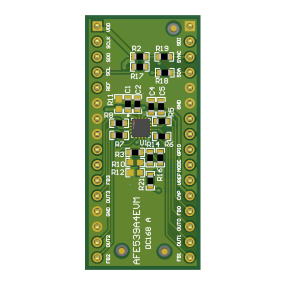
Page 23: Figure 4-7. Afe539A4Evm Pcb Components
Schematic, PCB Layout, and Bill of Materials Figure 4-7. AFE539A4EVM PCB Components Layout Figure 4-8. AFE539A4EVM Layers SLAU859 – JULY 2021 AFE539A4EVM Submit Document Feedback Copyright © 2021 Texas Instruments Incorporated... -
Page 24: Boostxl-Dac-Port Bill Of Materials
Keystone Test Point, Miniature, SMT Test Point, Miniature, SMT 5019 Keystone 4-Bit Bidirectional Multi-Voltage Level PW0014A LSF0204DPWR Texas Instruments Translator for Open-Drain & Push-Pull, PW0014A (TSSOP-14) AFE539A4EVM SLAU859 – JULY 2021 Submit Document Feedback Copyright © 2021 Texas Instruments Incorporated... -
Page 25: Afe539A4Evm Bill Of Materials
RC0603JR-070RL Yageo America R40, R44 RES, 33, 5%, 0.1 W, AEC-Q200 Grade 0, 0603 CRCW060333R0JNEA Vishay-Dale 0603 4.5 AFE539A4EVM Bill of Materials Table 4-2. AFE539A4EVM Bill of Materials Designator Quantity Value Description Package Reference Part Number Manufacturer !PCB Printed Circuit Board... - Page 26 STANDARD TERMS FOR EVALUATION MODULES Delivery: TI delivers TI evaluation boards, kits, or modules, including any accompanying demonstration software, components, and/or documentation which may be provided together or separately (collectively, an “EVM” or “EVMs”) to the User (“User”) in accordance with the terms set forth herein.
- Page 27 www.ti.com Regulatory Notices: 3.1 United States 3.1.1 Notice applicable to EVMs not FCC-Approved: FCC NOTICE: This kit is designed to allow product developers to evaluate electronic components, circuitry, or software associated with the kit to determine whether to incorporate such items in a finished product and software developers to write software applications for use with the end product.
- Page 28 www.ti.com Concernant les EVMs avec antennes détachables Conformément à la réglementation d'Industrie Canada, le présent émetteur radio peut fonctionner avec une antenne d'un type et d'un gain maximal (ou inférieur) approuvé pour l'émetteur par Industrie Canada. Dans le but de réduire les risques de brouillage radioélectrique à...
- Page 29 www.ti.com EVM Use Restrictions and Warnings: 4.1 EVMS ARE NOT FOR USE IN FUNCTIONAL SAFETY AND/OR SAFETY CRITICAL EVALUATIONS, INCLUDING BUT NOT LIMITED TO EVALUATIONS OF LIFE SUPPORT APPLICATIONS. 4.2 User must read and apply the user guide and other available documentation provided by TI regarding the EVM prior to handling or using the EVM, including without limitation any warning or restriction notices.
- Page 30 Notwithstanding the foregoing, any judgment may be enforced in any United States or foreign court, and TI may seek injunctive relief in any United States or foreign court. Mailing Address: Texas Instruments, Post Office Box 655303, Dallas, Texas 75265 Copyright © 2019, Texas Instruments Incorporated...
- Page 31 TI products. TI’s provision of these resources does not expand or otherwise alter TI’s applicable warranties or warranty disclaimers for TI products.IMPORTANT NOTICE Mailing Address: Texas Instruments, Post Office Box 655303, Dallas, Texas 75265 Copyright © 2021, Texas Instruments Incorporated...
Need help?
Do you have a question about the AFE539A4EVM and is the answer not in the manual?
Questions and answers