Table of Contents
Advertisement
Quick Links
AFE5818 16-Channel Analog Front End Evaluation Module
This user's guide gives a general overview of the AFE5818 evaluation module (EVM) and provides a
general description of the features and functions to be considered while using this module. This manual is
applicable to the AFE5818 analog front-end, and to the Rev. C version of the EVM hardware. The
AFE5818 EVM provides a platform for evaluating the AFE under various signal, clock, reference, and ADC
output formats. In addition, the EVM supports the testing of the LVDS interface. Note that if using the
LVDS interface, the TSW1400EVM capture card is required.
This user's guide refers to software HMC-DAQ GUI v.2.8 or higher, and HSDCPro Software v.4.1 or
higher and requires Microsoft
For any further questions regarding the EVM, GUI or device, please contact: AFE5818-support@list.ti.com
1
2
3
3.1
4
4.1
4.2
5
Appendix F
FAQ and Troubleshooting
1
AFE5818 EVM Hardware Overview
2
Provided Power Cable for J1 Connector
3
LVDS Evaluation Setup Overview
4
TSW1400EVM and AFE5818 EVM Hardware Setup for LVDS Capture
5
Connect to TSW EVM (TSW1400 Shown)
6
Connect to TSW EVM
7
Choose Firmware (AFE5818 Shown)
8
Update Firmware?
9
Firmware Download Progress Bar
10
TSW LEDs Turn On After FW Download
11
Launching Device GUI EXE
12
HMC-DAQ GUI Launches
13
Clock Configuration on AFE EVM for LVDS
14
AFE_RST Hardware Reset Button
15
Software Reset Button
SLOU430A - December 2015 - Revised February 2016
Submit Documentation Feedback
Windows
7 to function.
®
®
...................................................................................................
...................................................................................................
.......................................................................................
.............................................................................
..............................................................................................
............................................................................................
..............................................................................................
..........................................................................................
.................................................................................................
...............................................................................
..............................................................................................
........................................................................................
List of Figures
.......................................................................................
.................................................................................
.........................................................................................
...............................................................................
.......................................................................................................
....................................................................................
..........................................................................................................
.......................................................................................
...............................................................................
..............................................................................................
.................................................................................................
...........................................................................
.......................................................................................
.....................................................................................................
AFE5818 16-Channel Analog Front End Evaluation Module (EVM Rev. C)
Copyright © 2015-2016, Texas Instruments Incorporated
SLOU430A - December 2015 - Revised February 2016
Contents
..................................................................
...................................................
............................................
User's Guide
(EVM Rev. C)
4
5
6
6
8
8
9
16
18
31
35
37
38
57
4
5
6
8
9
9
10
10
10
11
11
12
12
13
13
1
Advertisement
Table of Contents

Related Manuals for Texas Instruments AFE5818


Summary of Contents for Texas Instruments AFE5818
-
Page 1: Table Of Contents
This manual is applicable to the AFE5818 analog front-end, and to the Rev. C version of the EVM hardware. The AFE5818 EVM provides a platform for evaluating the AFE under various signal, clock, reference, and ADC output formats. - Page 2 AFE5818 Rev C EVM Schematic 7 of 11 ................AFE5818 Rev C EVM Schematic 8 of 11 AFE5818 16-Channel Analog Front End Evaluation Module (EVM Rev. C) SLOU430A – December 2015 – Revised February 2016 Submit Documentation Feedback Copyright © 2015–2016, Texas Instruments Incorporated...
- Page 3 Default Header Configuration Table Rev.C ....................EVM Rev.C Testpoints ..................AFE5818 EVM Bill of Materials SLOU430A – December 2015 – Revised February 2016 AFE5818 16-Channel Analog Front End Evaluation Module (EVM Rev. C) Submit Documentation Feedback Copyright © 2015–2016, Texas Instruments Incorporated...
-
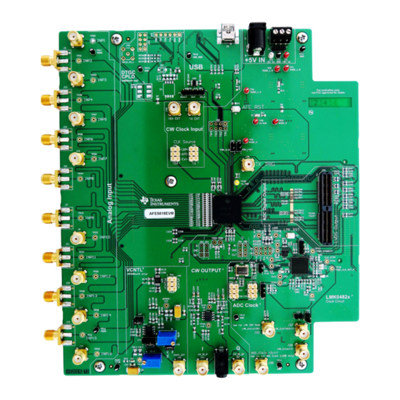
Page 4: Evm Hardware Overview
Figure 1. For more hardware details and the default jumper map, see Appendix AFE5818 16-Channel Analog Front End Evaluation Module (EVM Rev. C) SLOU430A – December 2015 – Revised February 2016 Submit Documentation Feedback Copyright © 2015–2016, Texas Instruments Incorporated... -
Page 5: Gui Software Installation
Figure 2. Provided Power Cable for J1 Connector GUI Software Installation The AFE5818 EVM and the TSW capture card EVM have individual software and both require software installations. Ensure that no USB connections are made to the EVMs until after the installations are complete. -
Page 6: Quick Views Of Evaluation Setups For Lvds Interface
EVM kit. USB Interface to PC: The USB connections from the AFE5818 EVM and TSW EVM to the PC are used for communication from the GUIs to the boards. USB 2.0 or 3.0 ports are both acceptable. - Page 7 For more information on clock configuration, see Section B.1.3. SLOU430A – December 2015 – Revised February 2016 AFE5818 16-Channel Analog Front End Evaluation Module (EVM Rev. C) Submit Documentation Feedback Copyright © 2015–2016, Texas Instruments Incorporated...
-
Page 8: Testing The Evm Data Capture With Lvds
A, connect the USB cable from PC to J5 (USB) located on the top side of the AFE5818 EVM. Connect the USB cable from PC to J5 (USB_IF) of the TSW1400 EVM. USB 2.0 or 3.0 ports are both acceptable for both EVMs. Note: TI recommends that the PC USB port be able to support USB2.0. -
Page 9: Capturing An Analog Input Signal With The Lvds Interface
Capturing an Analog Input Signal With the LVDS Interface This section describes the software setup for capturing an analog input using the AFE5818 EVM. If there is any issue with a data capture, refer to the troubleshooting section. Data capture is confirmed by using only the Quick Setup page of the HMC-DAQ GUI. Assuming the... - Page 10 8. When the firmware has finished downloading, several Green LEDs are lit on the TSW EVM. For the TSW1400, D5 (USER_LED3) may be on, and D6 is off. AFE5818 16-Channel Analog Front End Evaluation Module (EVM Rev. C) SLOU430A – December 2015 – Revised February 2016 Submit Documentation Feedback Copyright ©...
- Page 11 Figure 10. TSW LEDs Turn On After FW Download 9. The AFE5818 EVM GUI (HMC-DAQ) opens automatically at this time. Wait until this is finished to continue. If any errors arise at this time, consult a TI engineer. Figure 11. Launching Device GUI EXE SLOU430A –...
- Page 12 2. Press the AFE_RST button on the AFE EVM, located above the AFE device (SW1). Hold for 1 second. Alternatively, press the DUT RESET button on the HMC-DAQ GUI. AFE5818 16-Channel Analog Front End Evaluation Module (EVM Rev. C) SLOU430A – December 2015 – Revised February 2016 Submit Documentation Feedback Copyright ©...
- Page 13 If this is not the case, please consult the Appendix F section. There is most likely SLOU430A – December 2015 – Revised February 2016 AFE5818 16-Channel Analog Front End Evaluation Module (EVM Rev. C) Submit Documentation Feedback Copyright © 2015–2016, Texas Instruments Incorporated...
- Page 14 HSDCPro (found at the top of the spectrum graph). Blackman or Hanning works, do not use Rectangular. Figure 20. Capture Button AFE5818 16-Channel Analog Front End Evaluation Module (EVM Rev. C) SLOU430A – December 2015 – Revised February 2016 Submit Documentation Feedback...
- Page 15 Testing the EVM Data Capture With LVDS www.ti.com Figure 21. Analog Input Capture SLOU430A – December 2015 – Revised February 2016 AFE5818 16-Channel Analog Front End Evaluation Module (EVM Rev. C) Submit Documentation Feedback Copyright © 2015–2016, Texas Instruments Incorporated...
-
Page 16: Testing The Evm In Cw Mode
10 kHz and signals should be 90 degrees out of phase. 7. Trigger the oscilloscope on either channel. AFE5818 16-Channel Analog Front End Evaluation Module (EVM Rev. C) SLOU430A – December 2015 – Revised February 2016 Submit Documentation Feedback... - Page 17 Testing the EVM in CW Mode www.ti.com Figure 24. CW Output SLOU430A – December 2015 – Revised February 2016 AFE5818 16-Channel Analog Front End Evaluation Module (EVM Rev. C) Submit Documentation Feedback Copyright © 2015–2016, Texas Instruments Incorporated...
-
Page 18: Appendix A Software Installation
GUI used to control a suite of FPGA capture solutions including the TSW1400. Section A.2 provides details for installing Healthtech Multi-Channel Data Acquisition (HMC-DAQ), the software GUI which controls a suite of AFE and ADC solutions, including the AFE5818 . High Speed Data Converter Pro (HSDCPro) GUI Installation Go to the HSDCPro website. - Page 19 Next button as shown in Figure Figure 26. HSDCPro Install (TI License Agreement) 4. Read the License Agreement from Texas Instruments and select I accept the agreement, then press the Next button as shown in Figure Figure 27. HSDCPro Install (TI License Agreement) SLOU430A –...
- Page 20 Figure 28. HSDCPro Install (Install Directory) 6. Click Next to begin the installation, as in Figure Figure 29. HSDCPro Install (Installation Ready) Software Installation SLOU430A – December 2015 – Revised February 2016 Submit Documentation Feedback Copyright © 2015–2016, Texas Instruments Incorporated...
- Page 21 Figure 30. HSDCPro Install (Cypress Driver Install) 8. Click Finish to continue installation, as shown in Figure Figure 31. HSDCPro Install (Continue Cypress Driver Installation) SLOU430A – December 2015 – Revised February 2016 Software Installation Submit Documentation Feedback Copyright © 2015–2016, Texas Instruments Incorporated...
- Page 22 10. Finish HSDCPro installation by choosing the installation options and pressing Finish, as in Figure Figure 33. HSDCPro Install (Finish Installation) Software Installation SLOU430A – December 2015 – Revised February 2016 Submit Documentation Feedback Copyright © 2015–2016, Texas Instruments Incorporated...
- Page 23 Run as Administrator. Press the Next button once the graphic in Figure 34 appears. Figure 34. HMC-DAQ GUI Install (Begin Installation) 2. Read the Texas Instruments License Agreement and select I accept the agreement followed by the Next button, as in Figure Figure 35. HMC-DAQ GUI Install (TI License Agreement) SLOU430A –...
- Page 24 4. Allow the software to be installed in the default location by pressing the Next button, as in Figure Figure 37. HMC-DAQ GUI Install (Install Directory) Software Installation SLOU430A – December 2015 – Revised February 2016 Submit Documentation Feedback Copyright © 2015–2016, Texas Instruments Incorporated...
- Page 25 6. The window shown in Figure 39 appears showing that the installation is in progress. Figure 39. HMC-DAQ GUI Install (Installation Progress) SLOU430A – December 2015 – Revised February 2016 Software Installation Submit Documentation Feedback Copyright © 2015–2016, Texas Instruments Incorporated...
- Page 26 Figure 40. HMC-DAQ GUI Install (LabView Run-time Engine Installation) 8. Press the Next button, as in Figure Figure 41. HMC-DAQ GUI Install (LabView Run-time Engine Installation) Software Installation SLOU430A – December 2015 – Revised February 2016 Submit Documentation Feedback Copyright © 2015–2016, Texas Instruments Incorporated...
- Page 27 Figure 42. HMC-DAQ GUI Install (LabView Run-time Engine Installation) 10. Press the Next button, as in Figure Figure 43. HMC-DAQ GUI Install (LabView Run-time Engine Installation) SLOU430A – December 2015 – Revised February 2016 Software Installation Submit Documentation Feedback Copyright © 2015–2016, Texas Instruments Incorporated...
- Page 28 12. The run-time engine installs unless it has already been detected as should be the case if the HSDCPro GUI was already installed. In this case, the following message appears. Press the Cancel button, as in Figure Software Installation SLOU430A – December 2015 – Revised February 2016 Submit Documentation Feedback Copyright © 2015–2016, Texas Instruments Incorporated...
- Page 29 13. Press the Yes button to confirm, as in Figure Figure 46. HMC-DAQ GUI Install: (LabView RTE Cancel, if Installed Already) 14. Press the Finish button, as in Figure SLOU430A – December 2015 – Revised February 2016 Software Installation Submit Documentation Feedback Copyright © 2015–2016, Texas Instruments Incorporated...
- Page 30 HMC-DAQ is launched automatically from HSDCPro, once a device has been selected. Therefore, there is no need to launch HMC-DAQ manually and there is no need for a desktop shortcut. Software Installation SLOU430A – December 2015 – Revised February 2016 Submit Documentation Feedback Copyright © 2015–2016, Texas Instruments Incorporated...
-
Page 31: Appendix B Hardware Configuration
EVM that are useful for debug and general-use purposes. B.1.1 EVM Header Configuration The AFE5818 EVM is flexible in its configurability through the use of 2- and 3-pin headers. The default configuration of the EVM is set to facilitate initial testing, requiring minimal bench equipment. Figure 48 shows the default positions of all headers. -
Page 32: Default Header Configuration Table Rev.c
CW Output CW Quadrature-phase Output M/P – – B.1.2 EVM Testpoints Table 2 lists all test points on the AFE5818 EVM and their purposes. Table 2. EVM Rev.C Testpoints Testpoint Circuit Label Testpoint Description TP2,11–14 Digital Ground Reference for EVM... - Page 33 LVDS mode (S-E and Differential), and two options of clock input for JESD204B mode (Differential). Figure 49. EVM ADC Clock Source Configuration SLOU430A – December 2015 – Revised February 2016 Hardware Configuration Submit Documentation Feedback Copyright © 2015–2016, Texas Instruments Incorporated...
- Page 34 4. Also, connect an external clock generator to J32. Set the clock source to 400 MHz, and +15-dBm amplitude. Consult a TI engineer to use this mode. Hardware Configuration SLOU430A – December 2015 – Revised February 2016 Submit Documentation Feedback Copyright © 2015–2016, Texas Instruments Incorporated...
-
Page 35: Appendix C Triggering Options
See the TSW or HSDCPro manual for more information. Figure 51. HSDCPro Trigger Configuration for SW Figure 52. HSDCPro Trigger Configuration for SW trigger SLOU430A – December 2015 – Revised February 2016 Triggering Options Submit Documentation Feedback Copyright © 2015–2016, Texas Instruments Incorporated... - Page 36 See the TSW or HSDCPro manual for more information. Figure 53. HSDCPro Trigger Configuration for HW Figure 54. HSDCPro Trigger Configuration for HW External Trigger Triggering Options SLOU430A – December 2015 – Revised February 2016 Submit Documentation Feedback Copyright © 2015–2016, Texas Instruments Incorporated...
-
Page 37: Appendix D Common Hardware Modifications
The AFE EVM allows for external access to the SPI bus for the AFE only, not the LMK device. This is done by connecting SPI signals at J4 and removing R22 near U9 on the bottom side of the board. SLOU430A – December 2015 – Revised February 2016 Common Hardware Modifications Submit Documentation Feedback Copyright © 2015–2016, Texas Instruments Incorporated... -
Page 38: Appendix E Hardware Reference
SLOU430A – December 2015 – Revised February 2016 Hardware Reference AFE5818 EVM Hardware Overview The following images give an overview illustration of the EVM hardware. Figure 55. AFE5818 EVM Circuits Map Hardware Reference SLOU430A – December 2015 – Revised February 2016 Submit Documentation Feedback... - Page 39 AFE5818 EVM Hardware Overview www.ti.com Figure 56. AFE5818 EVM Block Diagram SLOU430A – December 2015 – Revised February 2016 Hardware Reference Submit Documentation Feedback Copyright © 2015–2016, Texas Instruments Incorporated...
- Page 40 Vout AFE58xx16 1.9V 1.66k 3.01k 280pF AFE58xx18 3.3V 5.1k 3.01k 158pF Figure 57. AFE5816 Rev C EVM Schematic 1 of 11 Hardware Reference SLOU430A – December 2015 – Revised February 2016 Submit Documentation Feedback Copyright © 2015–2016, Texas Instruments Incorporated...
- Page 41 Super Red VCCA VCCB C260 C261 SDOUT_PRE 0.1uF SDOUT 0.1uF SN74AVCH1T45DBVR Figure 58. AFE5818 Rev C EVM Schematic 2 of 11 SLOU430A – December 2015 – Revised February 2016 Hardware Reference Submit Documentation Feedback Copyright © 2015–2016, Texas Instruments Incorporated...
- Page 42 SMA_INP6 SMA_INP14 SMA_INP7 SMA_INP15 SMA_INP8 SMA_INP16 SMA_INP16 AGND AGND AGND AGND Figure 59. AFE5818 Rev C EVM Schematic 3 of 11 Hardware Reference SLOU430A – December 2015 – Revised February 2016 Submit Documentation Feedback Copyright © 2015–2016, Texas Instruments Incorporated...
- Page 43 AGND C181 0.1uF R102 0.1uF CW1X_CLEAN_P AGND C182 CLKP_1X 0.1uF AGND Figure 60. AFE5818 Rev C EVM Schematic 4 of 11 SLOU430A – December 2015 – Revised February 2016 Hardware Reference Submit Documentation Feedback Copyright © 2015–2016, Texas Instruments Incorporated...
- Page 44 10pF 2200pF 100pF 0.1uF Vcont TP49 C167 OSCINn 0.01uF 100 MHz Figure 61. AFE5818 Rev C EVM Schematic 5 of 11 Hardware Reference SLOU430A – December 2015 – Revised February 2016 Submit Documentation Feedback Copyright © 2015–2016, Texas Instruments Incorporated...
- Page 45 AFE5818ZBV DC_OUTP_IP CW_DC_OUTP_IP CW_DC_OUTP_QP DC_OUTP_QP DC_OUTM_IP CW_DC_OUTM_IP CW_DC_OUTM_QP DC_OUTM_QP AFE5818ZBV AFE5818ZBV Figure 62. AFE5818 Rev C EVM Schematic 6 of 11 SLOU430A – December 2015 – Revised February 2016 Hardware Reference Submit Documentation Feedback Copyright © 2015–2016, Texas Instruments Incorporated...
- Page 46 TSW_GPIO_2 DOUTP7 TSW_GPIO_3 DOUTM16 TSW_GPIO_4 DOUTP16 DCLKM TSW_GPIO_5 DCLKP TSW_GPIO_6 TSW_GPIO_7 Figure 63. AFE5818 Rev C EVM Schematic 7 of 11 Hardware Reference SLOU430A – December 2015 – Revised February 2016 Submit Documentation Feedback Copyright © 2015–2016, Texas Instruments Incorporated...
- Page 47 3300pF R168 AGND DC_OUTP_QP C238 1200pF AGND R181 C239 R182 DC_INM_QP Figure 64. AFE5818 Rev C EVM Schematic 8 of 11 SLOU430A – December 2015 – Revised February 2016 Hardware Reference Submit Documentation Feedback Copyright © 2015–2016, Texas Instruments Incorporated...
-
Page 48: Afe5818 Rev C Evm Schematic 9 Of
TGC_UP_DOWN_EXT TSW_GPIO_2 R140 TGC_SLOPE_EXT TSW_GPIO_3 R141 TGC_UP_DOWN_EXT CPLD_UD R142 TGC_SLOPE_EXT CPLD_SL Figure 65. AFE5818 Rev C EVM Schematic 9 of 11 Hardware Reference SLOU430A – December 2015 – Revised February 2016 Submit Documentation Feedback Copyright © 2015–2016, Texas Instruments Incorporated... -
Page 49: Afe5818 Rev C Evm Schematic 10 Of
0.1uF 0.1uF 0.1uF C134 49.9 0.1uF TR_EN_OUT_4 C135 49.9 0.1uF AGND Figure 66. AFE5818 Rev C EVM Schematic 10 of 11 SLOU430A – December 2015 – Revised February 2016 Hardware Reference Submit Documentation Feedback Copyright © 2015–2016, Texas Instruments Incorporated... -
Page 50: Afe5818 Rev C Evm Schematic 11 Of
IPC-A-610 Class 2, unless otherwise specified. Assembly Note Indication for all LEDs has been marked with their cathode side. Figure 67. AFE5818 Rev C EVM Schematic 11 of 11 Hardware Reference SLOU430A – December 2015 – Revised February 2016 Submit Documentation Feedback... -
Page 51: Afe5818 Evm Bill Of Materials
EVM Bill of Materials www.ti.com EVM Bill of Materials Table 3 lists the AFE5818 EVM bill of materials (BOM). Table 3. AFE5818 EVM Bill of Materials Designator Value Description Package Reference Part Number Alternate Part Number Alternate MFR C1, C2, C4, C6, C9, C10, 22 µF... - Page 52 EVM Bill of Materials www.ti.com Table 3. AFE5818 EVM Bill of Materials (continued) Designator Value Description Package Reference Part Number Alternate Part Number Alternate MFR C101, C103, C114, C115 1 µF CAP, CERM, 1 µF, 6.3 V, +/- 20%, X5R,...
- Page 53 EVM Bill of Materials www.ti.com Table 3. AFE5818 EVM Bill of Materials (continued) Designator Value Description Package Reference Part Number Alternate Part Number Alternate MFR Power Jack, mini, 2.1mm OD, R/A, TH Jack, 14.5x11x9mm RAPC722X Switchcraft Terminal Block, 3.5 mm, 3x1, Tin, TH Terminal Block, 3.5 mm, 3x1,...
- Page 54 EVM Bill of Materials www.ti.com Table 3. AFE5818 EVM Bill of Materials (continued) Designator Value Description Package Reference Part Number Alternate Part Number Alternate MFR R79, R80, R82, R84 RES, 750, 5%, 0.063 W, 0402 0402 CRCW0402750RJNED Vishay-Dale 60.4k RES, 60.4k ohm, 1%, 0.063W, 0402...
- Page 55 EVM Bill of Materials www.ti.com Table 3. AFE5818 EVM Bill of Materials (continued) Designator Value Description Package Reference Part Number Alternate Part Number Alternate MFR Ultralow-Noise, High PSRR, Fast, RF, DCQ0006A TPS79618DCQR Texas Texas Instruments 1A Low-Dropout Linear Regulator, Instruments...
- Page 56 EVM Bill of Materials www.ti.com Table 3. AFE5818 EVM Bill of Materials (continued) Designator Value Description Package Reference Part Number Alternate Part Number Alternate MFR J52, J54, J56, J58 Header, 100mil, 3x1, Gold, TH 3x1 Header TSW-103-07-G-S Samtec Connector, Male, 1.27 mm, 40x4, SMD Connector, Male, 1.27 mm,...
-
Page 57: Enable .Net Framework
– Missing Data output clock from the AFE to the FGPA. With LVDS, this could be the FCLK or DCLK. D5 of the TSW1400 should turn on, and if not, this is probably the reason. With JESD204B data, a SLOU430A – December 2015 – Revised February 2016 FAQ and Troubleshooting Submit Documentation Feedback Copyright © 2015–2016, Texas Instruments Incorporated... -
Page 58: Read Ddr Error For No Capture
Added the Triggering Options section................• Added the Common Hardware Modifications section........• Added the AFE5818 EVM Hardware Overview and Schematics sections to Appendix E..................• Updated the Bill of Materials in Appendix E..................• Added the FAQ and Troubleshooting section. - Page 59 STANDARD TERMS AND CONDITIONS FOR EVALUATION MODULES Delivery: TI delivers TI evaluation boards, kits, or modules, including any accompanying demonstration software, components, or documentation (collectively, an “EVM” or “EVMs”) to the User (“User”) in accordance with the terms and conditions set forth herein. Acceptance of the EVM is expressly subject to the following terms and conditions.
- Page 60 FCC Interference Statement for Class B EVM devices NOTE: This equipment has been tested and found to comply with the limits for a Class B digital device, pursuant to part 15 of the FCC Rules. These limits are designed to provide reasonable protection against harmful interference in a residential installation.
- Page 61 【無線電波を送信する製品の開発キットをお使いになる際の注意事項】 開発キットの中には技術基準適合証明を受けて いないものがあります。 技術適合証明を受けていないもののご使用に際しては、電波法遵守のため、以下のいずれかの 措置を取っていただく必要がありますのでご注意ください。 1. 電波法施行規則第6条第1項第1号に基づく平成18年3月28日総務省告示第173号で定められた電波暗室等の試験設備でご使用 いただく。 2. 実験局の免許を取得後ご使用いただく。 3. 技術基準適合証明を取得後ご使用いただく。 なお、本製品は、上記の「ご使用にあたっての注意」を譲渡先、移転先に通知しない限り、譲渡、移転できないものとします。 上記を遵守頂けない場合は、電波法の罰則が適用される可能性があることをご留意ください。 日本テキサス・イ ンスツルメンツ株式会社 東京都新宿区西新宿6丁目24番1号 西新宿三井ビル 3.3.3 Notice for EVMs for Power Line Communication: Please see http://www.tij.co.jp/lsds/ti_ja/general/eStore/notice_02.page 電力線搬送波通信についての開発キットをお使いになる際の注意事項については、次のところをご覧くださ い。http://www.tij.co.jp/lsds/ti_ja/general/eStore/notice_02.page SPACER EVM Use Restrictions and Warnings: 4.1 EVMS ARE NOT FOR USE IN FUNCTIONAL SAFETY AND/OR SAFETY CRITICAL EVALUATIONS, INCLUDING BUT NOT LIMITED TO EVALUATIONS OF LIFE SUPPORT APPLICATIONS.
- Page 62 Notwithstanding the foregoing, any judgment may be enforced in any United States or foreign court, and TI may seek injunctive relief in any United States or foreign court. Mailing Address: Texas Instruments, Post Office Box 655303, Dallas, Texas 75265 Copyright © 2015, Texas Instruments Incorporated...
- Page 63 IMPORTANT NOTICE Texas Instruments Incorporated and its subsidiaries (TI) reserve the right to make corrections, enhancements, improvements and other changes to its semiconductor products and services per JESD46, latest issue, and to discontinue any product or service per JESD48, latest issue.
Need help?
Do you have a question about the AFE5818 and is the answer not in the manual?
Questions and answers