Table of Contents
Advertisement
Quick Links
This document assists users in evaluating the AFE5807 and AFE5808 highly integrated analog front-end
devices through the use of the AFE5807/08EVM Evaluation Module. Included are setup instructions,
printed-circuit board art, bill of materials, and schematics.
.....................................................................................................................
1
2
3
3.1
3.2
...................................................................................................................
4
5
6
7
8
8.1
8.2
9
9.1
9.2
9.3
10
11
12
12.1
12.2
12.3
12.4
12.5
13
14
1
2
3
4
5
6
7
8
9
10
11
Windows is a trademark of Microsoft Corporation.
SLOU309 - December 2010
Submit Documentation Feedback
AFE5807/08EVM (Rev D) Evaluation Module
.......................................................................................................
......................................................................................
......................................................................................
.....................................................................................................
..................................................................................................
.....................................................................................................
..........................................................................................................
..............................................................................................
........................................................................................
..............................................................................................
....................................................................................
....................................................................................
...........................................................................................
..............................................................................................................
.......................................................................................................
...........................................................................................
................................................................................................
...............................................................................................................
.......................................................................................
.............................................................................................................
...................................................................................
......................................................................................
.......................................................................................................
................................................................................................................
.............................................................................................
..........................................................................................
Copyright © 2010, Texas Instruments Incorporated
Contents
.................................................................................
.....................................................................
........................................................................
.................................................................
List of Figures
....................................................
.........................................................................
.....................................................................
..........................................................................
AFE5807/08EVM (Rev D) Evaluation Module
User's Guide
SLOU309 - December 2010
............................................
2
2
3
3
3
5
6
6
7
8
8
10
12
12
13
14
16
18
20
20
21
22
23
24
25
31
3
5
11
12
13
14
15
16
17
19
20
1
Advertisement
Table of Contents

Related Manuals for Texas Instruments AFE5807EVM


Summary of Contents for Texas Instruments AFE5807EVM
-
Page 1: Table Of Contents
External ADC Sampling Clock Configuration ..................... External Vcntl Configuration ..................I/O, PWR, and USB Connector Windows is a trademark of Microsoft Corporation. SLOU309 – December 2010 AFE5807/08EVM (Rev D) Evaluation Module Submit Documentation Feedback Copyright © 2010, Texas Instruments Incorporated... -
Page 2: Overview
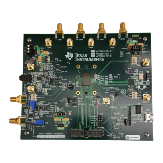
Figure 1 shows the default configuration of the EVM from the factory. The accompanying list identifies the basic components on the EVM board. SLOU309 – December 2010 AFE5807/08EVM (Rev D) Evaluation Module Submit Documentation Feedback Copyright © 2010, Texas Instruments Incorporated... -
Page 3: Software Installation And Operation
If the driver has not been installed, then the message "Window Found New Hardware" appears. As shown in the following illustration, the Wizard launches. Otherwise, skip this section, and go to Section SLOU309 – December 2010 AFE5807/08EVM (Rev D) Evaluation Module Submit Documentation Feedback Copyright © 2010, Texas Instruments Incorporated... - Page 4 Microsoft WHQL certified driver. Click on "Continue Anyway" to continue with the installation. If Windows XP is configured to ignore file signature warnings, no message appears. SLOU309 – December 2010 AFE5807/08EVM (Rev D) Evaluation Module Submit Documentation Feedback Copyright © 2010, Texas Instruments Incorporated...
-
Page 5: Test Setup
-5 V PowerSupply +5 V PowerSupply +6V supply ADC (external) sampling Vcntl Supply; Figure 2. HW Setup With Connection Between TSW1250EVM and AFE5807/08 SLOU309 – December 2010 AFE5807/08EVM (Rev D) Evaluation Module Submit Documentation Feedback Copyright © 2010, Texas Instruments Incorporated... -
Page 6: Power Up Afe5807/08
GUI has completely launched, LED41 and LED42 go off and the rest of the LEDS remain on. The GUI automatically configures the default setup. Select the ADC page to observe the default condition. SLOU309 – December 2010 AFE5807/08EVM (Rev D) Evaluation Module Submit Documentation Feedback Copyright © 2010, Texas Instruments Incorporated... -
Page 7: Launch Tsw1250 Gui
TSW1250EVM and AFE5807/08EVM is working properly. If a different message or an error message appears, contact TI FAE. Select AFE5807, 14 bits, MSB first from the GUI. SLOU309 – December 2010 AFE5807/08EVM (Rev D) Evaluation Module Submit Documentation Feedback Copyright © 2010, Texas Instruments Incorporated... -
Page 8: Test Afe5807/08
Message TEST AFE5807/08 Step 1: Time Domain • Select the Time Domain page from the TSW1250 GUI. • Uncheck Overlay unwrap waveform. SLOU309 – December 2010 AFE5807/08EVM (Rev D) Evaluation Module Submit Documentation Feedback Copyright © 2010, Texas Instruments Incorporated... - Page 9 Press the Capture button on the TSW1250 GUI. You will observe a ramping waveform on the TSW1250 GUI display area as shown in the following illustration. • Repeat for Channel 2 and Channel 8. SLOU309 – December 2010 AFE5807/08EVM (Rev D) Evaluation Module Submit Documentation Feedback Copyright © 2010, Texas Instruments Incorporated...
-
Page 10: Step 2: Single Tone Fft
• Select the Single Tone FFT page at the TSW1250 GUI. • Connect Channel 1 of the AFE5807EVM to a signal generator through an LP filter. If an LP filter is not present, the result will not be good. •... -
Page 11: User Interface: Single Fft Format
TEST AFE5807/08 www.ti.com Hanning Figure 3. User Interface: Single FFT Format SLOU309 – December 2010 AFE5807/08EVM (Rev D) Evaluation Module Submit Documentation Feedback Copyright © 2010, Texas Instruments Incorporated... -
Page 12: Hardware Setup, Cw Mode
Check CW Mode Enable. The LED41, LED42, and LED43 on AFE5807/08EVM all illuminate. • Select 500ohms for the gain control feedback resistor. SLOU309 – December 2010 AFE5807/08EVM (Rev D) Evaluation Module Submit Documentation Feedback Copyright © 2010, Texas Instruments Incorporated... -
Page 13: Step 2: Apply Input And Observe Outputs
The CW outputs (J12, J13) display the frequency I and Q signals at 10 kHz as shown in Figure 6. The GUI Gain Control Feedback Resistor can be used to vary the amplitude of the outputs. SLOU309 – December 2010 AFE5807/08EVM (Rev D) Evaluation Module Submit Documentation Feedback Copyright © 2010, Texas Instruments Incorporated... -
Page 14: External Clock For Cw Mode
Uninstalled Top layer of the EVM C156 Installed Uninstalled Top layer of the EVM C157 Installed Uninstalled Top layer of the EVM SLOU309 – December 2010 AFE5807/08EVM (Rev D) Evaluation Module Submit Documentation Feedback Copyright © 2010, Texas Instruments Incorporated... -
Page 15: Relevant Capacitors For Cw Mode, Top Side
Hardware Setup, CW Mode www.ti.com C154 C155 C156 C157 Figure 7. Relevant Capacitors for CW Mode, Top Side SLOU309 – December 2010 AFE5807/08EVM (Rev D) Evaluation Module Submit Documentation Feedback Copyright © 2010, Texas Instruments Incorporated... -
Page 16: External Adc Sampling Clock
1. Reconfigure JP9 as shown in the following illustration. The rest of the jumpers remain the same. 2. Connect the external generator as shown in Figure 3. Set the generator output to 40 MHz, 13 dBm. SLOU309 – December 2010 AFE5807/08EVM (Rev D) Evaluation Module Submit Documentation Feedback Copyright © 2010, Texas Instruments Incorporated... -
Page 17: External Adc Sampling Clock Configuration
4. If the generators for the ADC clock and input signal are synchronous, then choose Rectangular as the Windowing option; otherwise, use Hanning or Hamming. SLOU309 – December 2010 AFE5807/08EVM (Rev D) Evaluation Module Submit Documentation Feedback Copyright © 2010, Texas Instruments Incorporated... -
Page 18: External Vcntl
JP15 needs to be reconfigured to short the leftmost two pins. • A power supply is required to be connected as shown in Figure SLOU309 – December 2010 AFE5807/08EVM (Rev D) Evaluation Module Submit Documentation Feedback Copyright © 2010, Texas Instruments Incorporated... -
Page 19: External Vcntl Configuration
External Vcntl www.ti.com Power Supply JP15 Figure 10. External Vcntl Configuration SLOU309 – December 2010 AFE5807/08EVM (Rev D) Evaluation Module Submit Documentation Feedback Copyright © 2010, Texas Instruments Incorporated... -
Page 20: Board Configuration
Test points for USB data bus: From pin 1 to pin 9 the signals are: D0, D4, D2, D1, D7, D5, D6, and D3 AFE5807/08EVM (Rev D) Evaluation Module SLOU309 – December 2010 Submit Documentation Feedback Copyright © 2010, Texas Instruments Incorporated... -
Page 21: Cw Mode, Adc Clock
CMOS clock. Set it to the other side to use the external clock source. JP9/JP10 Short to power up onboard CMOS clock. External ADC clock Input. SLOU309 – December 2010 AFE5807/08EVM (Rev D) Evaluation Module Submit Documentation Feedback Copyright © 2010, Texas Instruments Incorporated... -
Page 22: Vcntl Control Input
External Vcntl input. The range is from 0 V to 1.5 V. Onboard Vcntl adjustment. Use JP15 pin 3 which has the text On-Board to monitor the Vcntl voltage level. SLOU309 – December 2010 AFE5807/08EVM (Rev D) Evaluation Module Submit Documentation Feedback Copyright © 2010, Texas Instruments Incorporated... -
Page 23: Leds
LED5V +5 V Green LED3.3VD +3.3 VD Orange LED3.3VA +3.3 VA Green LED1.8V +1.8 VV Green LED41 Clock Buffer Status Indicator LED42 SLOU309 – December 2010 AFE5807/08EVM (Rev D) Evaluation Module Submit Documentation Feedback Copyright © 2010, Texas Instruments Incorporated... -
Page 24: Miscellaneous Test Points
SDOUT read enable JP44 RESET input. Short to reset AFE5807. JP45 TP_5 control enable JP20 REFP voltage input JP21 REF_IN voltage input SLOU309 – December 2010 AFE5807/08EVM (Rev D) Evaluation Module Submit Documentation Feedback Copyright © 2010, Texas Instruments Incorporated... -
Page 25: Evm Printed-Circuit Board Layouts And Schematics
EVM Printed-Circuit Board Layouts and Schematics The following illustrations show the six layers of the AFE5807/08EVM board. Figure 16. Top Layer - Signal SLOU309 – December 2010 AFE5807/08EVM (Rev D) Evaluation Module Submit Documentation Feedback Copyright © 2010, Texas Instruments Incorporated... - Page 26 EVM Printed-Circuit Board Layouts and Schematics www.ti.com Figure 17. Second Layer - Ground SLOU309 – December 2010 AFE5807/08EVM (Rev D) Evaluation Module Submit Documentation Feedback Copyright © 2010, Texas Instruments Incorporated...
- Page 27 EVM Printed-Circuit Board Layouts and Schematics www.ti.com Figure 18. Third Layer - Power SLOU309 – December 2010 AFE5807/08EVM (Rev D) Evaluation Module Submit Documentation Feedback Copyright © 2010, Texas Instruments Incorporated...
- Page 28 EVM Printed-Circuit Board Layouts and Schematics www.ti.com Figure 19. Fourth Layer - Signal SLOU309 – December 2010 AFE5807/08EVM (Rev D) Evaluation Module Submit Documentation Feedback Copyright © 2010, Texas Instruments Incorporated...
- Page 29 EVM Printed-Circuit Board Layouts and Schematics www.ti.com Figure 20. Fifth Layer - Ground SLOU309 – December 2010 AFE5807/08EVM (Rev D) Evaluation Module Submit Documentation Feedback Copyright © 2010, Texas Instruments Incorporated...
- Page 30 EVM Printed-Circuit Board Layouts and Schematics www.ti.com Figure 21. Bottom Layer - Signal The schematic sheets are appended to the end of this document. SLOU309 – December 2010 AFE5807/08EVM (Rev D) Evaluation Module Submit Documentation Feedback Copyright © 2010, Texas Instruments Incorporated...
-
Page 31: Bill Of Materials
TYCO 4-103239-0X5 J16, JP50 HEADER,THU,5P HEADER, 1X5, .1CTRS ELECTRONICS SPC TECH 8431-1x9 JP18 HEADER,THU,9P HEADER, THU, MALE, 0.1LS, 9P, 1X9, 335H, 120TL SLOU309 – December 2010 AFE5807/08EVM (Rev D) Evaluation Module Submit Documentation Feedback Copyright © 2010, Texas Instruments Incorporated... - Page 32 RESISTOR, SMT, 0603, THIN FILM, 499 OHM 0.1%, 1/10W, R88, R89, R607 25ppm KYCON STX-3000 STEREO PHONE JACK, THU, 3 STEREO PHONE JACK, THU, 3 PIN, 3.5mm SLOU309 – December 2010 AFE5807/08EVM (Rev D) Evaluation Module Submit Documentation Feedback Copyright © 2010, Texas Instruments Incorporated...
- Page 33 TRIMPOT, THU, 10K, 10%, 0.5W, 100ppm, 25T BOURNS 3296W-1-205 TRIMPOT, THU, 3P TRIMPOT, THU, 2M, 10%, 0.5W, 100ppm, 25T SPECIAL NOTES AND INSTRUCTIONS SLOU309 – December 2010 AFE5807/08EVM (Rev D) Evaluation Module Submit Documentation Feedback Copyright © 2010, Texas Instruments Incorporated...
- Page 34 Evaluation Board/Kit Important Notice Texas Instruments (TI) provides the enclosed product(s) under the following conditions: This evaluation board/kit is intended for use for ENGINEERING DEVELOPMENT, DEMONSTRATION, OR EVALUATION PURPOSES ONLY and is not considered by TI to be a finished end-product fit for general consumer use. Persons handling the product(s) must have electronics training and observe good engineering practice standards.
- Page 35 IMPORTANT NOTICE Texas Instruments Incorporated and its subsidiaries (TI) reserve the right to make corrections, modifications, enhancements, improvements, and other changes to its products and services at any time and to discontinue any product or service without notice. Customers should obtain the latest relevant information before placing orders and should verify that such information is current and complete.
- Page 36 Mouser Electronics Authorized Distributor Click to View Pricing, Inventory, Delivery & Lifecycle Information: Texas Instruments AFE5808EVM...
Need help?
Do you have a question about the AFE5807EVM and is the answer not in the manual?
Questions and answers