Table of Contents
Advertisement
Quick Links
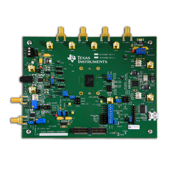
This document assists users in evaluating the AFE5808/08A highly integrated analog front-end devices
through the use of the AFE5808/08AEVM Evaluation Module. Included are setup instructions,
printed-circuit board art, bill of materials, and schematics.
.....................................................................................................................
1
2
3
...................................................................................................................
4
5
6
7
8
8.1
8.2
9
9.1
9.2
9.3
10
11
12
12.1
12.2
12.3
12.4
12.5
13
13.1
14
1
2
3
4
5
6
7
8
9
10
11
12
SLOU328A - November 2011 - Revised December 2011
Submit Documentation Feedback
AFE5808/08AEVM (Rev E) Evaluation Module
.......................................................................................................
......................................................................................
...................................................................................................
................................................................................................
.....................................................................................................
........................................................................................................
..............................................................................................
........................................................................................
..............................................................................................
....................................................................................
....................................................................................
...........................................................................................
..............................................................................................................
.......................................................................................................
...........................................................................................
................................................................................................
...............................................................................................................
.......................................................................................
........................................................................................................
.............................................................................................................
..................................................................................
......................................................................................
.......................................................................................................
................................................................................................................
.............................................................................................
..........................................................................................
..................................................................................
Copyright © 2011, Texas Instruments Incorporated
SLOU328A - November 2011 - Revised December 2011
Contents
.....................................................................
........................................................................
.................................................................
List of Figures
...........................................
....................................................
.........................................................................
.....................................................................
..........................................................................
AFE5808/08AEVM (Rev E) Evaluation Module
User's Guide
2
2
3
3
4
6
8
9
9
11
12
13
14
15
16
19
20
20
21
22
23
24
25
31
40
3
4
11
12
13
14
15
16
17
19
20
21
1
Advertisement
Table of Contents

Subscribe to Our Youtube Channel
Related Manuals for Texas Instruments AFE5808/08AEVM


Summary of Contents for Texas Instruments AFE5808/08AEVM
-
Page 1: Table Of Contents
SLOU328A – November 2011 – Revised December 2011 AFE5808/08AEVM (Rev E) Evaluation Module This document assists users in evaluating the AFE5808/08A highly integrated analog front-end devices through the use of the AFE5808/08AEVM Evaluation Module. Included are setup instructions, printed-circuit board art, bill of materials, and schematics. Contents ........................ -
Page 2: Overview
Bill of Materials Overview This document is intended to guide users step-by-step through the AFE5808/08AEVM Evaluation Module (EVM) setup and test . The EVM is shipped with a default configuration from the manufacturer. With this configuration, the onboard CMOS clock is used for a analog-to-digital converter sampling clock; the onboard oscillator is used for CW mode operation. -
Page 3: Software Installation And Operation
6. JP31 always set as Figure Software Installation and Operation The AFE5808/08AEVM GUI (SLOC230) can be downloaded from the TI Web site. Follow the directions in the Read Me First.pdf file to install the GUI and device driver Test Setup Two EVMs are required to evaluate the AFE5808/08A device. -
Page 4: Power Up Afe5808/08A
Figure 2. HW Setup With Connection Between TSW1250EVM and AFE5808/08A Power Up AFE5808/08A Power up the AFE5808/08AEVM by applying +5 V and –5 V to the P1 connector. After power up is complete, four green LEDS and two red LEDS are turned on as shown in the following illustration. - Page 5 Power Up AFE5808/08A www.ti.com LED 1.8V SLOU328A – November 2011 – Revised December 2011 AFE5808/08AEVM (Rev E) Evaluation Module Submit Documentation Feedback Copyright © 2011, Texas Instruments Incorporated...
-
Page 6: Launch Afe5808/08A Gui
Select the ADC page to observe the default condition. The following illustration shows the Default Condition on the ADC page. SLOU328A – November 2011 – Revised December 2011 AFE5808/08AEVM (Rev E) Evaluation Module Submit Documentation Feedback Copyright © 2011, Texas Instruments Incorporated... - Page 7 Launch AFE5808/08A GUI www.ti.com SLOU328A – November 2011 – Revised December 2011 AFE5808/08AEVM (Rev E) Evaluation Module Submit Documentation Feedback Copyright © 2011, Texas Instruments Incorporated...
-
Page 8: Launch Tsw1250 Gui
Launch TSW1250 GUI Launch the TSW1250 GUI. The Message window displays the following message to indicate that the setup of the TSW1250EVM and AFE5808/08AEVM is working properly. If a different message or an error message appears, contact TI FAE. Select AFE5808/08A, 14 bits, MSB first from the GUI. -
Page 9: Test Afe5808/08A
Uncheck Overlay unwrap waveform. Overlay unwrap waveform • From the AFE5808/08A GUI, go to the ADC page, and then select Ramp. SLOU328A – November 2011 – Revised December 2011 AFE5808/08AEVM (Rev E) Evaluation Module Submit Documentation Feedback Copyright © 2011, Texas Instruments Incorporated... - Page 10 TI FAE to troubleshoot the problem. • On the AFE5808/08A GUI, change Test Pattern from Ramp to None for the next step. SLOU328A – November 2011 – Revised December 2011 AFE5808/08AEVM (Rev E) Evaluation Module Submit Documentation Feedback Copyright © 2011, Texas Instruments Incorporated...
-
Page 11: Step 2: Single Tone Fft
• Select the Single Tone FFT page at the TSW1250 GUI. • Connect Channel 1 of the AFE5808/08AEVM to a signal generator through an LP filter. If an LP filter is not present, the result will not be good. •... -
Page 12: Hardware Setup, Cw Mode
Q) (J12, 13) Analog input (note absence of filter) (J1 - J8) Figure 4. Setup for CW Mode SLOU328A – November 2011 – Revised December 2011 AFE5808/08AEVM (Rev E) Evaluation Module Submit Documentation Feedback Copyright © 2011, Texas Instruments Incorporated... -
Page 13: Step 1: Switch To Cw Mode
• Go to the CW Mode page. • Check CW Mode Enable. The LED41, LED42, and LED43 on AFE5808/08AEVM all illuminate. • Select 500ohms for the gain control feedback resistor. Figure 5. Switching From Default (ADC) Mode Panel to CW Mode Panel SLOU328A –... -
Page 14: Step 2: Apply Input And Observe Outputs
GUI Gain Control Feedback Resistor can be used to vary the amplitude of the outputs. Figure 6. CW Outputs SLOU328A – November 2011 – Revised December 2011 AFE5808/08AEVM (Rev E) Evaluation Module Submit Documentation Feedback Copyright © 2011, Texas Instruments Incorporated... -
Page 15: External Clock For Cw Mode
Top layer of the EVM C154 C155 C156 C157 Figure 7. Relevant Capacitors for CW Mode, Top Side SLOU328A – November 2011 – Revised December 2011 AFE5808/08AEVM (Rev E) Evaluation Module Submit Documentation Feedback Copyright © 2011, Texas Instruments Incorporated... -
Page 16: External Adc Sampling Clock
2. Connect the external generator as shown in Figure 3. Set the generator output to 40 MHz, 13 dBm. SLOU328A – November 2011 – Revised December 2011 AFE5808/08AEVM (Rev E) Evaluation Module Submit Documentation Feedback Copyright © 2011, Texas Instruments Incorporated... -
Page 17: External Adc Sampling Clock Configuration
4. If the generators for the ADC clock and input signal are synchronous, then choose Rectangular as the Windowing option; otherwise, use Hanning or Hamming. SLOU328A – November 2011 – Revised December 2011 AFE5808/08AEVM (Rev E) Evaluation Module Submit Documentation Feedback Copyright © 2011, Texas Instruments Incorporated... - Page 18 External ADC Sampling Clock www.ti.com 5. The test procedure is the same for the CMOS ADC clock. SLOU328A – November 2011 – Revised December 2011 AFE5808/08AEVM (Rev E) Evaluation Module Submit Documentation Feedback Copyright © 2011, Texas Instruments Incorporated...
-
Page 19: External Vcntl
• A power supply is required to be connected as shown in Figure Figure 10. External Vcntl Configuration SLOU328A – November 2011 – Revised December 2011 AFE5808/08AEVM (Rev E) Evaluation Module Submit Documentation Feedback Copyright © 2011, Texas Instruments Incorporated... -
Page 20: Board Configuration
JP18 Test points for USB data bus: From pin 1 to pin 9 the signals are: D0, D4, D2, D1, D7, D5, D6, and D3 AFE5808/08AEVM (Rev E) Evaluation Module SLOU328A – November 2011 – Revised December 2011 Submit Documentation Feedback... -
Page 21: Cw Mode, Adc Clock
Board Configuration www.ti.com 12.2 CW Mode, ADC Clock Figure 12. AFE5808/08AEVM Jumper Locations Table 3. CW Mode, ADC Clock Clock Reference Description Type Designator J9/J10 External CW Mode clock. The default is using onboard oscillator. CW output for I-channel via an external operational amplifier. The EVM has converted the differential signal CW_IP_OUTP and CW_IP_OUTM into this single-ended output through an operational amplifier. -
Page 22: Vcntl Control Input
Onboard Vcntl adjustment. Use JP15 pin 3 which has the text On-Board to monitor the Vcntl voltage level. SLOU328A – November 2011 – Revised December 2011 AFE5808/08AEVM (Rev E) Evaluation Module Submit Documentation Feedback Copyright © 2011, Texas Instruments Incorporated... -
Page 23: Leds
Board Configuration www.ti.com 12.4 LEDs The AFE5808/08AEVM has seven LEDs. Their locations are shown in Figure 14. Their ON/OFF states demonstrate the normal operation of the power supplies and the PLL status of the clock buffer. LED 1.8V Figure 14. AFE5808/08AEVM LED Location Table 5. -
Page 24: Miscellaneous Test Points
Board Configuration www.ti.com 12.5 Miscellaneous Test Points Figure 15. AFE5808/08AEVM Test Point Locations Table 6. Test Points Reference Designator Description TP9, TP12, TP13,TP34 AFE808/08A device test pin M8, L5, M5, and M9 JP19 REFM voltage input JP31 SDOUT read enable JP44 RESET input. -
Page 25: Evm Printed-Circuit Board Layouts And Schematics
EVM Printed-Circuit Board Layouts and Schematics www.ti.com EVM Printed-Circuit Board Layouts and Schematics The following illustrations show the six layers of the AFE5808/08AEVM board. Figure 16. Top Layer - Signal SLOU328A – November 2011 – Revised December 2011 AFE5808/08AEVM (Rev E) Evaluation Module Submit Documentation Feedback Copyright ©... - Page 26 EVM Printed-Circuit Board Layouts and Schematics www.ti.com Figure 17. Second Layer - Ground SLOU328A – November 2011 – Revised December 2011 AFE5808/08AEVM (Rev E) Evaluation Module Submit Documentation Feedback Copyright © 2011, Texas Instruments Incorporated...
- Page 27 EVM Printed-Circuit Board Layouts and Schematics www.ti.com Figure 18. Third Layer - Power SLOU328A – November 2011 – Revised December 2011 AFE5808/08AEVM (Rev E) Evaluation Module Submit Documentation Feedback Copyright © 2011, Texas Instruments Incorporated...
- Page 28 EVM Printed-Circuit Board Layouts and Schematics www.ti.com Figure 19. Fourth Layer - Signal SLOU328A – November 2011 – Revised December 2011 AFE5808/08AEVM (Rev E) Evaluation Module Submit Documentation Feedback Copyright © 2011, Texas Instruments Incorporated...
- Page 29 EVM Printed-Circuit Board Layouts and Schematics www.ti.com Figure 20. Fifth Layer - Ground SLOU328A – November 2011 – Revised December 2011 AFE5808/08AEVM (Rev E) Evaluation Module Submit Documentation Feedback Copyright © 2011, Texas Instruments Incorporated...
- Page 30 EVM Printed-Circuit Board Layouts and Schematics www.ti.com Figure 21. Bottom Layer - Signal SLOU328A – November 2011 – Revised December 2011 AFE5808/08AEVM (Rev E) Evaluation Module Submit Documentation Feedback Copyright © 2011, Texas Instruments Incorporated...
-
Page 31: Schematics
EVM Printed-Circuit Board Layouts and Schematics www.ti.com 13.1 Schematics Figure 22. Schematic 1 of 9 SLOU328A – November 2011 – Revised December 2011 AFE5808/08AEVM (Rev E) Evaluation Module Submit Documentation Feedback Copyright © 2011, Texas Instruments Incorporated... - Page 32 EVM Printed-Circuit Board Layouts and Schematics www.ti.com Figure 23. Schematic 2 of 9 SLOU328A – November 2011 – Revised December 2011 AFE5808/08AEVM (Rev E) Evaluation Module Submit Documentation Feedback Copyright © 2011, Texas Instruments Incorporated...
- Page 33 EVM Printed-Circuit Board Layouts and Schematics www.ti.com Figure 24. Schematic 3 of 9 SLOU328A – November 2011 – Revised December 2011 AFE5808/08AEVM (Rev E) Evaluation Module Submit Documentation Feedback Copyright © 2011, Texas Instruments Incorporated...
- Page 34 EVM Printed-Circuit Board Layouts and Schematics www.ti.com Figure 25. Schematic 4 of 9 SLOU328A – November 2011 – Revised December 2011 AFE5808/08AEVM (Rev E) Evaluation Module Submit Documentation Feedback Copyright © 2011, Texas Instruments Incorporated...
- Page 35 EVM Printed-Circuit Board Layouts and Schematics www.ti.com Figure 26. Schematic 5 of 9 SLOU328A – November 2011 – Revised December 2011 AFE5808/08AEVM (Rev E) Evaluation Module Submit Documentation Feedback Copyright © 2011, Texas Instruments Incorporated...
- Page 36 EVM Printed-Circuit Board Layouts and Schematics www.ti.com Figure 27. Schematic 6 of 9 SLOU328A – November 2011 – Revised December 2011 AFE5808/08AEVM (Rev E) Evaluation Module Submit Documentation Feedback Copyright © 2011, Texas Instruments Incorporated...
- Page 37 EVM Printed-Circuit Board Layouts and Schematics www.ti.com Figure 28. Schematic 7 of 9 SLOU328A – November 2011 – Revised December 2011 AFE5808/08AEVM (Rev E) Evaluation Module Submit Documentation Feedback Copyright © 2011, Texas Instruments Incorporated...
- Page 38 EVM Printed-Circuit Board Layouts and Schematics www.ti.com Figure 29. Schematic 8 of 9 SLOU328A – November 2011 – Revised December 2011 AFE5808/08AEVM (Rev E) Evaluation Module Submit Documentation Feedback Copyright © 2011, Texas Instruments Incorporated...
- Page 39 EVM Printed-Circuit Board Layouts and Schematics www.ti.com Figure 30. Schematic 9 of 9 SLOU328A – November 2011 – Revised December 2011 AFE5808/08AEVM (Rev E) Evaluation Module Submit Documentation Feedback Copyright © 2011, Texas Instruments Incorporated...
-
Page 40: Bill Of Materials
SMA COAX STRAIGHT PCB CURRENT P/N IS 901-144-8RFX Digi-key ARFX1231-ND J11, J12, J13 TEXAS INSTRUMENTS AFE5808/08A CUSTOMER PROVIDE AFE5808/08A Texas Instruments AFE5808/08A AFE5808/08AEVM (Rev E) Evaluation Module SLOU328A – November 2011 – Revised December 2011 Submit Documentation Feedback Copyright © 2011, Texas Instruments Incorporated... - Page 41 RES,SMT,0402 RESISTOR,SMT,0402,1K,1/16W,1%,100ppm Digi-Key 541-1.00KLTR-ND VISHAY CRCW04021002F100 RES,SMT,0402 RESISTOR,SMT,0402,10K,1/16W,1%,100ppm Digi-Key RHM10.0KLTR-ND VISHAY CRCW04022002F100 R71, R110 RES,SMT,0402 RESISTOR,SMT,0402,20K,1/16W,1%,100ppm Digi-Key ERJ-2RKF2002X SLOU328A – November 2011 – Revised December 2011 AFE5808/08AEVM (Rev E) Evaluation Module Submit Documentation Feedback Copyright © 2011, Texas Instruments Incorporated...
- Page 42 2029K-ND ELECTRONICS 4-40THR .750"L ALUM KEYSTONE H703-ND Machine Screw, 4-40 SCREW MACHINE PHIL 4-40X1/4 SS Digi-Key H703-ND ELECTRONICS AFE5808/08AEVM (Rev E) Evaluation Module SLOU328A – November 2011 – Revised December 2011 Submit Documentation Feedback Copyright © 2011, Texas Instruments Incorporated...
- Page 43 NOTE: ASTERISK(*) NEXT TO PART MANUFACTURER'S NAME DENOTES POSSIBLE LONG LEAD TIME ITEM. RoHs note : all parts should comply with RoHs and Lead free, as well as the PCBs. SLOU328A – November 2011 – Revised December 2011 AFE5808/08AEVM (Rev E) Evaluation Module Submit Documentation Feedback Copyright © 2011, Texas Instruments Incorporated...
- Page 44 Evaluation Board/Kit Important Notice Texas Instruments (TI) provides the enclosed product(s) under the following conditions: This evaluation board/kit is intended for use for ENGINEERING DEVELOPMENT, DEMONSTRATION, OR EVALUATION PURPOSES ONLY and is not considered by TI to be a finished end-product fit for general consumer use. Persons handling the product(s) must have electronics training and observe good engineering practice standards.
- Page 45 IMPORTANT NOTICE Texas Instruments Incorporated and its subsidiaries (TI) reserve the right to make corrections, modifications, enhancements, improvements, and other changes to its products and services at any time and to discontinue any product or service without notice. Customers should obtain the latest relevant information before placing orders and should verify that such information is current and complete.
Need help?
Do you have a question about the AFE5808/08AEVM and is the answer not in the manual?
Questions and answers