Stuart Turner MAINSBOOST iBOOST F200 Installation, Operation & Maintenance Instructions Manual
Hide thumbs
Also See for MAINSBOOST iBOOST F200:
Table of Contents
Advertisement
Quick Links
MAINSBOOST iBOOST
Installation, Operation & Maintenance
Instructions
Please leave this instruction booklet with the home owner as it
contains important warranty, maintenance and safety information
Read this manual carefully before commencing installation.
This manual covers the following products:
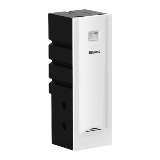
iBOOST F200
Pt. No. 46668
Please note images are representative only and
may not portray your model
iBOOST V200
Pt. No. 46711
Advertisement
Table of Contents


Need help?
Do you have a question about the MAINSBOOST iBOOST F200 and is the answer not in the manual?
Questions and answers