Table of Contents
Advertisement
Quick Links
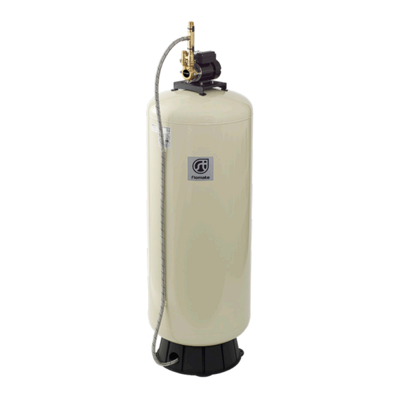
MAINSBOOST
Flomate MBF Pumps
Installation & Maintenance Instructions
Please leave this instruction booklet with the owner as it contains important
guarantee, maintenance and safety information
Read this manual carefully before commencing installation.
This manual covers the following products:
MBF 100-1-15
Pt. No. 46635
MBF 300-1-15
Pt. No. 46637
MBF 200-1-15
Pt. No. 46636
PATENT
APPROVED
GB 2494485 A
CE compliant product
3
Advertisement
Table of Contents


Need help?
Do you have a question about the MAINSBOOST MBF Series and is the answer not in the manual?
Questions and answers