Table of Contents
Advertisement
Installation, Operation & Maintenance
Instructions
Please leave this instruction booklet with the home owner as it contains
important guarantee, maintenance and safety information
Read this manual carefully before commencing installation.
This manual covers the following products:
Monsoon U1.5 bar Twin
Pt. No. 46505
Pt. No. 46505 EXP
Monsoon U2.0 bar Twin
Pt. No. 46480
Pt. No. 46480 EXP
Monsoon U3.0 bar Twin
Pt. No. 46410
Pt. No. 46410 EXP
FOR POSITIVE OR NEGATIVE HEAD APPLICATIONS
Pt. No. 46505 ROI
Pt. No. 46480 ROI
Pt. No. 46410 ROI
Monsoon U4.0 bar Twin
Pt. No. 46411
Pt. No. 46411 EXP
Monsoon U4.5 bar Twin
Pt. No. 46412
Pt. No. 46412 EXP
Pt. No. 46411 ROI
Pt. No. 46412 ROI
CE compliant product
Advertisement
Table of Contents

Related Manuals for Stuart Turner Monsoon Series


Summary of Contents for Stuart Turner Monsoon Series
- Page 1 Installation, Operation & Maintenance Instructions Please leave this instruction booklet with the home owner as it contains important guarantee, maintenance and safety information Read this manual carefully before commencing installation. This manual covers the following products: Monsoon U1.5 bar Twin Monsoon U4.0 bar Twin Pt.
- Page 2 PRODUCT DESCRIPTION Electric motor driven twin ended peripheral pumps complete with an automatic control system, consisting of flow switches, pressure switch and pressure vessel and electronic controls. APPLICATION Monsoon Universal pumps are suitable for positive or negative head installation conditions. The pumps are designed for whole house pressure boosting applications in vented stored water systems.
-
Page 3: Table Of Contents
CONTENTS Page Checklist ............4 Pre-Installation . -
Page 4: Checklist
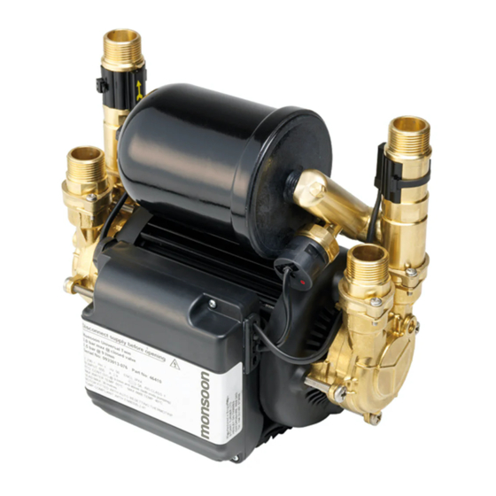
IMPORTANT: With the pump removed from its packaging check for any damage prior to installation. If any damage is found contact Stuart Turner Ltd within 24 hours of receipt. Note: This image is for reference only. Fig. 1 Item Description... -
Page 5: Pre-Installation
This installation book refers to UK pipework and pumps supplied with hoses suitable for 22 mm pipework. If you have purchased a product suitable for ROI (Republic of Ireland) it will be supplied with hoses suitable for 21 mm pipework. If you have purchased a product suitable for Export it will be supplied with hoses suitable for G ¾... -
Page 6: Important Facts - Read Before Commencing Installation
1 IMPORTANT FACTS: READ BEFORE COMMENCING PUMP INSTALLATION A. Water storage capacity. 1.11 The hot and cold water storage capacity must be sufficient to meet the flow rates required by the pumped equipment and any other water using fittings and appliances, which may be operated simultaneously. -
Page 7: Location
2.21 Direction of flow: Ensure the water flow is in the direction of the arrow that is marked on the flow switch reed clamp (vertically upwards). 2.22 Flexible hoses: Only use the Stuart Turner hose set supplied with the pump. 2.23 Isolating valves: Separate system isolating valves (non restrictive) must be fitted to allow easy pump service. - Page 8 2.25 Non-preferred pump location: If it is necessary to position the Pump above the secondary tapping on the hot cylinder it is fed by, the risk of introducing air will be increased. To avoid this risk one of the two following solutions must be adopted: The use of a Stuart Top Entry (TE) cylinder flange.
- Page 9 Cold water connection: 2.26 The cold water supply: Must be a DEDICATED AIR FREE supply via a tank connector, and must be positioned at a slightly lower level (25 mm minimum) than the feed pipe to the hot water cylinder. Do not connect to the mains.
-
Page 10: Pump Connections
3 PUMP CONNECTIONS Do not use stainless steel, chrome or nickel plated pipe with the flexible hose push-in plumbing connections. Do not introduce solder flux into the joint or surrounding area as connectors will be attacked and may fail. All solder joints should be completed and flux residues removed before final connection to push-in connections, on the flexible hose. - Page 11 3.12 Hose to pipework: 1. The hoses are fitted with plastic push-in connectors, which must only be connected to the following: 22 mm dia. pipework in the UK 21 mm dia pipework in the ROI Ensure the pipe is free from all score marks and deformities in the area of the insertion depth (Fig.
- Page 12 3.13 Typical Low Level Installation: In certain installations it may be necessary to install a 90° bend on the inlet or outlet connections of the pump before the flexible hose to accommodate a low level installation. Below are some preferred connection options. All connections seal on the pump body using a fibre or rubber sealing washer.
-
Page 13: Electrical Installation
4 ELECTRICAL INSTALLATION 4.11 Regulations: The electrical installation must be carried out in accordance with the current national electrical regulations and installed by a qualified person. 4.12 Safety: In the interests of electrical safety a 30 mA residual current device (R.C.D. not supplied) should be installed in the supply circuit. This may be part of a consumer unit or a separate unit. -
Page 14: Wiring Diagram
If the supply cord is to be changed or is damaged, it must be replaced with a special cord assembly available from Stuart Turner or one of their approved repairers. On disassembly note the cord retention and routing system. Re-assemble to the same pattern. - Page 15 4.24 Cable Gland Fitting Instructions: Fig. 12 To enable correct assembly of the cable gland the ‘O’-ring (Fig. 12 item 1) must be placed over the cable before the clamping insert (Fig. 12 item 2) can be tightened. Note: Cable diameter range:- 6.5 mm to 9.5 mm. 4.25 Supply Cord Extension: The pumps are fitted with a supply cord to the following specification:- All models .
-
Page 16: Commissioning
5 COMMISSIONING 5.11 System Flushing: This pump incorporates push-in connectors and plastic components that must not come into contact with solder flux, acid-based descalents or aggressive cleaning agents. The pipework system should be flushed out prior to the pump being connected to ensure any contaminants/chemical residues and foreign bodies are removed from elsewhere in the system. - Page 17 Carefully check pump and pipework for leaks whilst pump running and stationary before leaving the installation unattended. 5.15 For Further Technical Support: Phone the Stuart Turner PumpAssist team on +44 (0) 800 31 969 80. Our staff are trained to help and advise you over the phone.
-
Page 18: Maintenance
6 MAINTENANCE 6.11 Turn off water supplies to the pump and release pressure by opening water outlets before attempting maintenance. 6.12 Inlet strainer: The inlet strainers may require periodical cleaning. The frequency of this operation is dependent upon installation conditions. The strainer is located in the inlet assembly of the pump casing (see Fig. - Page 19 6.14 Pressure vessel: Should ever the need arise for the vessel to have its air charge checked or replenished, it should be carried out as follows: - a) Isolate pump electrically. b) Isolate hot and cold water supplies via the integral pump isolating valve located in the flexible hoses (see Section 3 - Pump Connections).
-
Page 20: Technical Specification
8.8 Kg 9.2 Kg 11.1 Kg 11.6 Kg Stuart Turner reserve the right to amend the specification in line with its policy of continuous development of its products. Note: For information on other voltages/frequencies which are not shown, consult PumpAssist on +44 (0) 800 31 969 80. - Page 21 *Note: The maximum pressure that can be applied to the pump under any installation conditions. **Note: A stored water temperature of 60°C is considered sufficient to meet all normal requirements and will minimize deposition of scale in hard water areas. ***Note: Both ends pumping 4.5 l/min and above.
-
Page 22: Trouble Shooting
Check fuse (see fuse section). Check circuit breaker is set. Check wiring connections. Pump Jammed. If motor ‘Buzzes’ switch off power and contact Stuart Turner. Damaged pressure switch. Turn off power. Release system water pressure. Turn on power, pump should start. If NOT contact Stuart Turner. - Page 23 If the pump fails to operate normally after three attempts to re-start, then please consult Stuart Turner PumpAssist +44 (0) 800 31 969 80. 8.13 Fault Finding: The PCB is also fitted with a “power on” indicator light. This will remain illuminated when mains power is supplied to the board.
- Page 24 IMPORTANT – Ensure there is no contact with any of the internal parts of the terminal box. Briefly reconnect the mains power supply to the pump – the ‘power on light should illuminate if the pump has been correctly wired. Isolate the mains electrical power supply from the pump.
- Page 25 If this does not happen, this indicates a possible fault with the reed switch or the P.C.B which is located within the terminal box. These should be checked electrically. Consult Stuart Turner for further instructions. Body Reed Clamp...
-
Page 26: Guarantee
Proof of purchase should accompany the returned unit to avoid delay in investigation and dealing with your claim. You should obtain appropriate insurance cover for any loss or damage which is not covered by Stuart Turner Ltd in this provision. Please record here for your records. TYPE NO. - Page 27 Installers – Register with Stuart Turner and move up to Approved Installer status We receive thousands of enquiries every month from people seeking a Stuart Turner installer and by registering your details with us, we can offer consumers the opportunity to quickly locate an installer in their area.
-
Page 28: Declaration Of Conformity
Signed ......... Stuart Turner are an approved company to BS EN ISO 9001:2008...
Need help?
Do you have a question about the Monsoon Series and is the answer not in the manual?
Questions and answers