Table of Contents
Advertisement
Quick Links
Advertisement
Table of Contents

Related Manuals for Agilent Technologies G1992A


Summary of Contents for Agilent Technologies G1992A
- Page 1 Agilent G1992A Nanospray Ion Source User Guide...
- Page 2 Notices Warranty Safety Notices © Agilent Technologies, Inc. 2012 No part of this manual may be reproduced in The material contained in this docu- any form or by any means (including elec- ment is provided “as is,” and is sub-...
- Page 3 In This Guide… This guide contains information to install and set up the Nanospray Ion Source. Installation In this chapter you install the source and prepare the system for analysis. Mass Reference Solution This chapter describes how to use the Mass Reference Solution to calibrate the Nanospray Ion Source.
- Page 4 Nanospray Ion Source User Guide...
-
Page 5: Table Of Contents
Content Installation Upgrade Preparation To remove the ESI or Agilent Jet Stream source To upgrade the gas distributor To upgrade the stainless steel end plate To assemble and install the new spray shield and gas diverter assembly Installation To install the source To set the position of the Counter Electrode To set up MassHunter program for the Nanospray Ion Source To install the power cord and camera... - Page 6 Contents Reference Parts List Component Alignment Hole Layout Nanospray Ion Source User Guide...
-
Page 7: Installation
Agilent G1992A Nanospray Ion Source User Guide Installation Upgrade Preparation To remove the ESI or Agilent Jet Stream source To upgrade the gas distributor To upgrade the stainless steel end plate To assemble and install the new spray shield and gas diverter... -
Page 8: Upgrade Preparation
To remove the ESI or Agilent Jet Stream source Autotune is not supported with the Agilent G1992A Nanospray Ion Source. Before N O T E changing the source, do all tuning with the ESI or Agilent Jet Stream source. Calibration can still be done with the Nanospray Ion Source. -
Page 9: To Upgrade The Gas Distributor
Installation To upgrade the gas distributor Newer model gas distributors are required to support the improved resistive or dielectric capillary. If your gas distributor looks like the one in Figure replace it with the new one. 1 Remove the chamber and capillary high voltage cable leads from the T-nut connectors. - Page 10 Installation Figure 2 Remove the old gas distributor 4 Install the new gas distributor (p/n G1964-20303) with the solid side facing the PTFE wall. Position it so that it is flush with the PTFE plate. Figure 3 G1964-20303 Gas Distributor Nanospray Ion Source User Guide...
- Page 11 Installation Figure 4 Install the new gas distributor 5 Reinstall the PTFE end plate support block with the stainless steel ring. Make sure that the new gas distributor is positioned properly before installing and tightening the screws to avoid damage to the new gas distributor.
-
Page 12: To Upgrade The Stainless Steel End Plate
Installation To upgrade the stainless steel end plate If the screws that hold the end plate in position are pan heads, install the Nanospray Desolvation Upgrade Kit (p/n G1988-60009). This upgrade reduces any arcing that can occur to the raised head screws. Before you begin, make sure that you have the parts for Nanospray Desolvation Upgrade Kit (p/n G1988-60009) -
Page 13: To Assemble And Install The New Spray Shield And Gas Diverter Assembly
Installation To assemble and install the new spray shield and gas diverter assembly Before you begin, make sure that you have the parts for the Spray Shield Kit (p/n G1988-60007) listed in Table 8 on page 62. 1 Slide the Wave washer over the appropriate spray shield: •... - Page 14 Installation Figure 7 Radial gas diverter and winged nut 4 After all of the parts are assembled, rinse all of these parts with Isopropanol in a clean glass beaker at least three times. 5 After the parts are rinsed, remove the parts from the beaker and place them on a lint free cloth.
- Page 15 Installation 7 Install the spray shield. Figure 9 Installed spray shield assembly. (Multibore vortex spray shield shown) 8 Verify that the desolvation chamber end plate screws have good clearance to the end plate. If the screw heads are too close to the winged spray shield nut, arcing can occur. WA R N I N G Nanospray Ion Source User Guide...
-
Page 16: Installation
Installation Installation The source can be configured in three ways: Orthogonal Orientation Sample enters from above. The needle is at right angles to the MS capillary. Adjustment is along Z and Y axes. Camera is to the left, viewing the spray orthogonally. -
Page 17: To Install The Source
Installation To install the source 1 Align the hinge pins with their respective holes on the desolvation assembly. The source must be at an angle of less than 90 degrees with respect to the desolvation chamber. 2 Slide the hinge pins down into their seated position, and rotate the source into contact with the desolvation chamber. -
Page 18: To Set The Position Of The Counter Electrode
Installation To set the position of the Counter Electrode For best orthogonal Nanospray Ion Source operation, the Counter Electrode needs to be about 7 mm away from the end of the winged spray shield cap. The instrument must be in Standby mode or turned off to do this step. Otherwise, the WA R N I N G spray chamber high voltage electronics will be energized and present a shock hazard. - Page 19 Installation Figure 11 Nanospray Slide Assembly removed. 3 Loosen the set screw for the Counter Electrode using the 1.5 mm hex wrench Figure 12 Removing the Nanospray Slide Assembly provides easier access to the set screw. Nanospray Ion Source User Guide...
- Page 20 Installation 4 Insert the electrode spacing tool (p/n GT430-20358) between the Counter Electrode and the spray shield. The tool must touch both the Counter Electrode and the spray shield for correct positioning. Lightly tighten the set screw to secure the position of Counter Electrode.
-
Page 21: To Set Up Masshunter Program For The Nanospray Ion Source
Installation To set up MassHunter program for the Nanospray Ion Source 1 In the MassHunter Acquisition program, make sure that the source type is set to HPLC-Chip in the Tune Panel. 2 Set the drying gas flow and temperature parameters. See Table Operating the source with parameters above these set points can result in reduced performance, and can lead to frequent needle clogs. -
Page 22: To Install The Power Cord And Camera
Installation To install the power cord and camera 1 Plug in the power source and camera power cords: a Locate the power contacts on the lower-right of the spray chamber. Figure 14 Power contacts b Plug the camera power cord into either of the two power contacts. c Plug the 12V DC power supply for the source into the remaining power contact. - Page 23 Installation Figure 15 BNC adapter inserted between the camera plug (right) and the video capture card cable. 4 Ground the Needle Sleeve Assembly: a Attach one end of a push-clip ground line to the Needle Sleeve Assembly. b Attach the other end to a convenient ground location, such as a ground lug on the source.
- Page 24 Installation 5 Install the camera: a Insert and rotate the Camera Ring (with the camera) until the detent on the ring snaps into alignment with the spring plunger on the source. b Run the video capture software, until you get an image of the source interior.
-
Page 25: To Assemble The Infusion Sample Delivery System
Installation To assemble the Infusion Sample Delivery System This task describes how to assemble and install an infusion sample delivery system. The assembly is used to introduce tuning mix for LC/MS calibration. Use extreme caution when setting up experiments with any type of needle, WA R N I N G especially conductive ones. -
Page 26: To Infuse Solution Through The Infusion Sample Delivery System
Installation To infuse solution through the Infusion Sample Delivery System 1 Draw calibrant solution into the Syringe. 2 Connect the Syringe to the Syringe Adapter at the end of the assembled Infusion Sample Delivery System. 3 Insert the Needle Sleeve Assembly into the Nanospray Slide Assembly. -
Page 27: To Assemble The Extension Tube Column Support Assembly For Lc Analysis
Installation To assemble the Extension Tube column support assembly for LC analysis The LC transfer line is attached to the analytical column, which is attached to a needle assembly. The needle assembly is held in the Needle Sleeve Assembly. Needle Sleeve Assembly is inserted into the Nanospray Ion Source through the Nanospray Slide... - Page 28 Installation Figure 17 Extension tube attached to the Needle Sleeve Assembly. 2 Attach the analytical column to the needle. Figure 18 Analytical column attached to the needle, seated in the Needle Sleeve Assem- bly. Nanospray Ion Source User Guide...
- Page 29 Installation 3 Attach the analytical column to the LC transfer line. Figure 19 Analytical column attached to the LC transfer line. 4 Attach the Tube Clamp to the Nut. The Tube Clamp adds support to the column. Figure 20 Tube Clamp attached to the Nut.
- Page 30 Installation Figure 21 Completed Extension Tube column support assembly. Nanospray Ion Source User Guide...
- Page 31 Installation 5 Install the Nanospray Slide Assembly. Figure 22 Extension Tube column support assembly installed in the orthogonal configu- ration. If you need to change the orientation of the Nanospray Slide Assembly inline analysis, see “To install the Nanospray Slide Assembly for inline analysis”...
-
Page 32: To Install The Needle Sleeve Assembly Into The Nanospray Ion Source
Installation To install the Needle Sleeve Assembly into the Nanospray Ion Source 1 Start the video capture software so that the camera display is shown on the computer monitor. 2 Position the Nanospray Slide Assembly (on top of the Nanospray Ion Source) at the midway point of its travel length. - Page 33 Installation Figure 24 The needle becomes visible at the top of the video capture screen. 4 After the needle is safely positioned in the spray chamber, fully insert the Needle Sleeve Assembly into the Nanospray Slide Assembly. Make sure that the needle is roughly equidistant from the spray shield and the Counter Electrode.
- Page 34 Installation 5 Use the horizontal and vertical adjustment knobs to adjust the final position of the needle. Figure 26 Adjustment knobs to position the needle. Figure 27 Correct needle position. Nanospray Ion Source User Guide...
- Page 35 Installation 6 Infuse calibrant into the source at a flow rate of 18 µL/hour. Look for a small droplet of calibrant solution to form at the needle tip. Figure 28 Small droplet forming at the needle tip. An increase in the capillary voltage causes the spray to form.
-
Page 36: To Install The Nanospray Slide Assembly For Inline Analysis
Installation To install the Nanospray Slide Assembly for inline analysis Do these steps to change the Nanospray Slide Assembly from the standard Orthogonal Orientation to either the Inline Horizontal Orientation Inline Sideways Orientation. Before you begin, make sure that you have the Camera Plate Camera Plug. - Page 37 Installation Figure 30 Removing the Nanospray Slide Assembly from the spray chamber. 5 Install the Camera Plate onto the top of the Nanospray Ion Source. Notice the orientation of the spring plunger in Figure When the plate orientation is correct, the camera snaps into proper position.
- Page 38 Installation 6 For Inline Horizontal Orientation, install the Camera Plug into the Camera Plate. The Camera Plug snaps into the Camera Plate. Figure 32 Camera Plug inserted into Camera Plate. 7 Remove the Nanospray Front Plate. Angle the Counter Electrode and pin to clear the opening in the spray chamber.
- Page 39 Installation 8 For Inline Horizontal Orientation, install the Nanospray Slide Assembly. Make sure that the slide movement is up and down. Figure 34 Nanospray Slide Assembly installed for Inline Horizontal Orientation. 9 For Inline Sideways Orientation: a Install the Nanospray Slide Assembly rotated clockwise as shown.
- Page 40 Installation 10 Install the extension tube column support assembly. See “To install the Needle Sleeve Assembly into the Nanospray Ion Source” on page 32. Nanospray Ion Source User Guide...
-
Page 41: To Adjust The Led Camera Light
Installation To adjust the LED camera light You can adjust the LED housing position to control glare and get the best spray image on the camera. The LED housing can be adjusted from outside the chamber, even while experiments are in progress. •... - Page 42 Installation Nanospray Ion Source User Guide...
-
Page 43: Mass Reference Solution
Agilent G1992A Nanospray Ion Source User Guide Mass Reference Solution To prepare the Low Mass IRM stock solution To prepare the IRM working solution To apply the IRM solutions To enable reference mass correction To clean the wick and wick cover Reference mass solutions are only used with the 6200 Series TOF LC/MS and the 6500 Series Q-TOF LC/MS. - Page 44 Mass Reference Solution Do not mix acetonitrile and FC-70 together before you apply them to the wick. They are N O T E immiscible and will not form a solution. They can be applied sequentially to the wick, however. Nanospray Ion Source User Guide...
-
Page 45: To Prepare The Low Mass Irm Stock Solution
Mass Reference Solution To prepare the Low Mass IRM stock solution This step prepares 10 mL of 1000 µg/ml methyl stearate in acetonitrile. Before you begin, make sure that you have: • reagent-grade acetonitrile • methyl stearate (p/n G1982-85003) 1 Into a suitable container, add the contents listed in Table Table 2 Low Mass IRM stock solution... -
Page 46: To Prepare The Irm Working Solution
Mass Reference Solution To prepare the IRM working solution This step prepares 1 mL of 100 µg/mL methyl stearate and 2% (v/v) HP-1221 in acetonitrile. Before you begin, make sure that you have: • reagent-grade acetonitrile • Low Mass IRM stock solution •... -
Page 47: To Apply The Irm Solutions
Mass Reference Solution To apply the IRM solutions You need to adjust the amount of solution to apply or its concentration to suit your needs. These compounds are designed to persist in the ionization region and are difficult to remove completely. Therefore, for the first few applications, apply smaller amounts until the response of your system under your analysis conditions is known. - Page 48 Mass Reference Solution Figure 36 Dispensing solution into one of two IRM filling ports. 5 Wait about five minutes for the reagent-grade acetonitrile to evaporate at a typical standby source temperature of 300°C. The five minute pause minimizes the chances of arcing when the instrument is turned on. 6 Load a pipette with 200 µL of the FC-70 liquid (p/n G1982-85002).
- Page 49 Mass Reference Solution • 1 scan/second (9,816 transients/scan) • 200 µL of IRM working solution allowed to evaporate, followed by 200 µL FC-70 liquid (p/n G1982-85002) • drying gas temperature: 325 °C • gas flow: 5 L/minute • mobile phase: 300 nL/minute of 0.1% formic acid in 97/3 water/acetonitrile.
-
Page 50: To Enable Reference Mass Correction
Mass Reference Solution To enable reference mass correction 1 In the MassHunter Acquisition program, in the Reference Mass tab, enter the m/z value. Mark the check the box in front of the entry. 2 Repeat for the other IRM compound if it is used. 3 Check the Enable Reference Mass box. - Page 51 Mass Reference Solution When the IRM solutions are used repeatedly, a residual amount of the IRM compounds builds up in the interface assembly itself, requiring less frequent addition of the IRM solutions to maintain usable abundances. The IRM compounds persist in the interface assembly and yield signals for an extended period of time.
-
Page 52: To Clean The Wick And Wick Cover
Mass Reference Solution To clean the wick and wick cover 1 Use a T-6 driver to remove the four screws from the wick cover. 2 Use tweezers to remove the wick. 3 Soak the wick in a suitable organic solvent such as acetonitrile or LC flushing solvent to clean the wick. -
Page 53: Safety
Agilent G1992A Nanospray Ion Source User Guide Safety Safety Issues Safety Symbols This chapter contains safety information. -
Page 54: Safety Issues
Safety Safety Issues Agilent designed the Nanospray Ion Source to minimize safety hazards: • ESI and nanospray needles are grounded. • High voltage components are enclosed inside of chambers. However, you still need to be aware of several other potential safety issues when you operate the Nanospray Ion Source. - Page 55 Safety Do not use metal or otherwise conductive needles. If a conductive needle touches WA R N I N G the spray shield, the source can short. High temperatures Some parts in the Nanospray Ion Source operate at or reach temperatures high enough to cause serious burns.
- Page 56 Safety Do not wear dangling, conductive items such as necklaces, earrings, or other items WA R N I N G that can enter the source while it is in operation. A shock can result. Biohazardous residue The Nanospray Ion Source interface does not ionize all of the sample and solvent.
- Page 57 Safety Cleanliness Cleanliness and the prevention of accidental contamination during maintenance are very important. Contamination of the interior of the vacuum system or the sample path can affect the results of your analyses. • Always wear clean gloves when handling parts that come in contact with the sample path.
-
Page 58: Safety Symbols
Safety Safety Symbols NOTE These symbols are placed on the product where it is necessary for you to refer to the manual in order to understand a hazard. WARNING This symbol is placed on the product within the area where hazardous voltage is present or shock hazard can occur. - Page 59 Agilent G1992A Nanospray Ion Source User Guide Reference Parts List Component Alignment Hole Layout This chapter contains reference information.
- Page 60 Reference Parts List This section contains a description of all of the parts included with Nanospray Ion Source. Nanospray Ion Source - Outside Table 5 Nanospray Ion Source - Outside Part Description Part Number ❶ Nanospray Slide Assembly G1988-60002 ❷ Camera Assembly G1982-60458 ❸...
- Page 61 Reference Nanospray Ion Source - Inside Table 6 Nanospray Ion Source - Inside Part Description Part Number ❶ Counter Electrode G1982-20008 ❷ Probe Receptacle 0.975 inch 1400-3275 ❷ Probe Contact 1:32 inch 1400-3276 ❸ Nanospray Wick Cover G1988-20006 ❸ Nanospray IRM Wick G1988-20021 ❹...
- Page 62 Reference Nanospray Desolvation Upgrade Kit (p/n G1988-60009) Table 7 Nanospray Desolvation Upgrade Kit (p/n G1988-60009) Part Part Number T-nut connectors G1946-20111 stainless steel end plate G1946-20156 gold screws G1960-20148 Spray Shield Kit (p/n G1988-60007) Table 8 Spray Shield Kit (p/n G1988-60007) Part Part number Contact spring...
- Page 63 Reference Table 8 Spray Shield Kit (p/n G1988-60007) Part Part number Winged spray shield nut G1982-20011 Wave washer G1982-20012 Single bore spray shield G1982-20111 Multibore vortex spray shield G1988-20023 Single bore inline spray shield G1988-20038 Nanospray Ion Source User Guide...
- Page 64 Reference Infusion Sample Delivery System ❿ ❽ ❹ ❾ ❻ ❺ ❼ ❸ ❶ ❷ Table 9 Infusion Sample Delivery System Part Description Part Number ❶ Syringe 5190-1512 • SST needle ❷ Syringe Adapter 0100-2647 • F126S 1/32-inch nut • 1/32-inc to 1/16-inch reducing union •...
- Page 65 Reference Sleeve Assembly and Extension Tube Table 10 Sleeve Assembly and Extension Tube Part Description Part Number ❶ Upper Sleeve Assembly G1988-60004 • includes Conductive Gasket ❷ Lower Sleeve Assembly G1988-60005 • includes Conductive Gasket ❸ Extension Tube G1988-20033 ❹ Tube Clamp G1988-20001 ❺...
- Page 66 Reference Camera Plate and Plug Table 11 Camera Plate and Plug Description Part Number Camera Plate G1988-20002 Camera Plug G1988-20039 Nanospray Ion Source User Guide...
- Page 67 Reference Component Alignment When the Nanospray Slide Assembly is removed and reinstalled, small misalignments can occur. Stop Buttons are included to help realign the Nanospray Slide Assembly after removal. Slide the component into contact with the appropriate Stop Button, and tighten the component mounting screws.
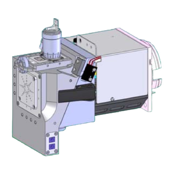
- Page 68 Reference Hole Layout Extra holes on the Nanospray Ion Source are to mount accessories. ❶ ❷ ❸ ❹ ❹ Table 12 Nanospray Ion Source front view Part Description Quantity ❶ M3 holes to mount extra components ❷ M3 holes for Stop Buttons ❸...
- Page 69 Reference ❺ ❶ ❹ ❷ ❸ Table 13 Nanospray Ion Source top view Part Description Quantity ❶ M4 hole: Spring-loaded plunger for camera Ring ❷ M3 holes to mount extra components. ❸ M3 holes for Stop Buttons. ❹ M3 holes to mount extra components. ❺...
- Page 70 Reference ❶ ❷ Table 14 Nanospray Ion Source side view Part Description Quantity ❶ M4 hole to attach Protective Cover (G1988-60003) ❷ M4 hole for spring-loaded plunger; provides safety grounding for LED shaft Nanospray Ion Source User Guide...
- Page 71 Reference ❶ Table 15 Nanospray Ion Source inside view Part Description Quantity ❶ M2 holes to mount the Wick Cover. Be careful when you service the wick. Use light tightening force. Nanospray Ion Source User Guide...
- Page 72 Reference Nanospray Ion Source User Guide...
- Page 74 In This Book This guide describes the step to upgrade, install, and use the Nanospray Ion Source. © Agilent Technologies, Inc. 2012 November, 2012 *G1988-90000* G1988-90000...