Table of Contents
Advertisement
Quick Links
Advertisement
Table of Contents

Related Manuals for Agilent Technologies G1888


Summary of Contents for Agilent Technologies G1888
- Page 1 Agilent G1888 Network Headspace Sampler User Information Agilent Technologies...
- Page 2 Notices © Agilent Technologies, Inc. 2004 Warranty Safety Notices No part of this manual may be reproduced in The material contained in this docu- any form or by any means (including elec- ment is provided “as is,” and is sub-...
- Page 3 Provides the purpose of this manual and an overview of its contents. It identifies the intended reader and lists the conventions used throughout the manual. Introduction to Headspace and to the G1888 Network Headspace Sampler Provides an overview of headspace theory and practice. It describes the instrument and its modes of operation.
- Page 4 Running a Sample Summarizes operation of the Headspace Sampler to run a sample. Maintaining the Instrument Describes maintenance procedures including changing the sample loop, transfer line, needle, valves, and EPROM. Troubleshooting and Error Messages Lists the possible causes and solutions for chromatography problems or instrument failure.
-
Page 5: Table Of Contents
Gases General warnings Safety and Regulatory Certifications Information Symbols Electromagnetic compatibility Sound Emission Certification for Federal Republic of Germany Fuses Cleaning Recycling the Product Introduction to Headspace and to the G1888 Network Headspace Sampler Overview of Headspace Analysis User Information... - Page 6 The G1888 Network Headspace Sampler Oven Heated zones Vial tray Sampling system Transfer line Keypad and display Pneumatics Principles of Operation General operation Power on diagnostics Standby Condition Vial pressurization Filling the sample loop Loop equilibration Injecting the sample End of cycle and vial recovery...
- Page 7 The Active Method Key Zone Temps Event Times Vial Parameters Menu Key Load Method Store Method Chain Methods Pressures Advanced Functions Using an Advanced Function List of Advanced Functions Advanced Function Descriptions Stabilize Time Parameter Increment Vial number and location Keyboard Lock Manual Operation Pressure Units...
- Page 8 Diagnostic Preparing a Sample Sample Preparation Loading the Sample Tray Entering a Method Entering a Method How to create a method Entering Zone Temperatures Setting Event Times Setting Vial Parameters Storing and Loading Methods Storing a method Loading a method Chaining Methods Activate a Method Chain Deactivate a Method Chain...
- Page 9 Vial Pressurization and Time Vial pressurization Vial pressurization time Optimizing Carrier Gas Flow Running a Sample Running a Sample Setting Conditions Flow rates Setting the carrier gas flow rate using MPC Setting the vial pressurization gas pressure using MPC Setting carrier flow using EPC Setting vial pressurization flow using EPC Maintaining the Instrument Maintenance Schedule...
- Page 10 Setup Running the restriction test Pressure decay test Zone Calibration Recommended tools Procedure Fuse locations Troubleshooting and Error Messages Table of Errors Chromatographic Results No peaks or reduced sensitivity Poor retention time reproducibility Poor area count reproducibility Carryover in air or solvent blanks Unwanted background noise or peaks Vial Handling Vial not dropped...
- Page 11 Open or short Zone at or near ambient Zone does not stabilize Analysis aborted due to temperature error Pressure Readings GC goes not ready during a run GC pressure reading does not match Headspace Sampler pressure reading Pressures are below normal operating pressures Synchronization With GC Start or GC Ready: GC Does Not Start Communication Between the PC and Headspace Sampler...
- Page 12 User Information...
-
Page 13: Introduction
Agilent G1888 Network Headspace Sampler User Information Introduction About this Manual Video supplements Intended User Conventions Important Safety Warnings Many internal parts of the instrument carry dangerous voltages Electrostatic discharge is a threat to instrument electronics Many parts are dangerously hot... -
Page 14: About This Manual
About this Manual The G1888 Network Headspace Sampler User Information manual explains how to use the G1888 Network Headspace Sampler. It includes all the basic information the user needs to develop methods, use the sampler to carry out analyses, and maintain and troubleshoot the sampler. -
Page 15: Intended User
This manual is intended for users who understand the basics of gas chromatography. Although the manual contains some headspace theory, it primarily provides operating, maintenance, and troubleshooting information for the G1888 Network Headspace Sampler. This manual describes using the Headspace Sampler in standalone mode. -
Page 16: Conventions
Introduction Conventions The following conventions are used in this manual: 1 Braces { } enclose a generic name for which you should substitute specific information. For example, {setpoint} means you should key in the numeric value you desire for the setpoint. 2 Text in Bold means that you should press the key by that name. -
Page 17: Important Safety Warnings
Introduction Important Safety Warnings Before moving on, there are several important safety notices that you should always keep in mind when using the Headspace Sampler. Many internal parts of the instrument carry dangerous voltages If the instrument is connected to a power source, even if the power switch is off, potentially dangerous voltages exist on: •... -
Page 18: Many Parts Are Dangerously Hot
Introduction them, wear a grounded wrist strap and take other antistatic precautions. Wear a grounded wrist strap any time you must remove the electronics cover. Many parts are dangerously hot Many parts of the instrument operate at temperatures high enough to cause serious burns. These parts include but are not limited to: •... -
Page 19: General Warnings
Introduction General warnings • Perform periodic leak checks on supply lines, fittings, and pneumatic plumbing to prevent a potentially hazardous condition. • To avoid a potential shock hazard when using liquid solution to locate leaks, turn the main power switch off and disconnect the main power cord. -
Page 20: Safety And Regulatory Certifications
ISM est conforme a la norme NMB—001 du Canada. The instrument is designed and manufactured under a quality system registered to ISO 9001. Information The Agilent Technologies Headspace Sampler meets the following IEC (International Electro-Technical Commission) classifications: Safety Class I, Transient Overvoltage Category II, Pollution Degree 2. -
Page 21: Symbols
Failure to comply with these precautions violates safety standards of design and the intended use of the instrument. Agilent Technologies assumes no liability for the customer’s failure to comply with these requirements. See accompanying instructions for more information. -
Page 22: Sound Emission Certification For Federal Republic Of Germany
4 Make sure that all peripheral devices are also certified. 5 Make sure that appropriate cables are used to connect the device to peripheral equipment. 6 Consult your equipment dealer, Agilent Technologies, or an experienced technician for assistance. 7 Changes or modifications not expressly approved by Agilent Technologies could void the user’s authority to operate the... -
Page 23: Fuses
Introduction Fuses Table 1 lists the fuses required for proper operation. These fuses should only be accessed by Agilent service personnel. Fuses Table 1 Fuse designation Location Fuse rating and type F2, F3 Power line module 10A 250V, glass tube Terminal near 8A 250V, glass tube transformer... - Page 24 Introduction User Information...
-
Page 25: Introduction To Headspace And To The G1888 Network Headspace Sampler
End of cycle and vial recovery Standard headspace extraction Multiple headspace extraction with multiple vial puncture This chapter briefly describes the theory and application of headspace analysis. It describes the parts of the G1888 Network Headspace Sampler and its modes of operation. Agilent Technologies... -
Page 26: Overview Of Headspace Analysis
Introduction to Headspace and to the G1888 Network Headspace Sampler Overview of Headspace Analysis Your new Headspace Sampler is a tool for introducing volatiles and some semi-volatiles that are contained in liquid or solid samples into a gas chromatograph. The analytical technique is called “static headspace gas chromatography.”... - Page 27 Introduction to Headspace and to the G1888 Network Headspace Sampler compound in both the gas phase and the sample becomes smaller, although the ratio remains constant. The logs of the peak areas versus the extraction number are plotted to obtain quantitative data about the compound of interest.
-
Page 28: The G1888 Network Headspace Sampler
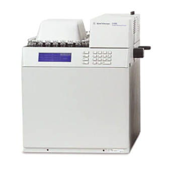
Introduction to Headspace and to the G1888 Network Headspace Sampler The G1888 Network Headspace Sampler The G1888 Network Headspace Sampler provides an automated method to run up to 70 samples consecutively without operator attention. The sampler’s microprocessor optimizes the time spent for each run according to the values programmed in by the operator. - Page 29 Introduction to Headspace and to the G1888 Network Headspace Sampler Transfer line Sample tray Keypad Screen Overview of the G1888 Network Headspace Sampler (from the front of the instrument) Figure 1 User Information...
-
Page 30: Oven
Vent Power switch RS232 port LAN port Power cord Overview of the G1888 Network Headspace Sampler (from the back of the instrument) Figure 2 The Headspace Sampler is made up of the following components: Oven The oven contains a circular aluminum sample carousel that holds up to twelve 10-mL or 20-mL sample vials. -
Page 31: Heated Zones
Introduction to Headspace and to the G1888 Network Headspace Sampler Heated zones There are three heated zones. They are the vial oven, the loop, and the transfer line. Each heated zone can be set to a specific temperature or turned off. -
Page 32: Keypad And Display
Introduction to Headspace and to the G1888 Network Headspace Sampler Keypad and display The Headspace Sampler has a 19–key elastomeric keypad with a graphic LCD display. All functions of the sampler are controlled from the keypad with the exception of EPC, which is controlled from the GC or ChemStation. - Page 33 Introduction to Headspace and to the G1888 Network Headspace Sampler Flow controller Transfer line Pressure sensor board Six port injection valve Toggle switch Carrier gas pneumatic system for the Headspace Sampler Figure 4 Pressure regulator Pressure sensor board Toggle switch...
-
Page 34: Principles Of Operation
Introduction to Headspace and to the G1888 Network Headspace Sampler Principles of Operation General operation When the instrument is switched on, the sampler moves the first vial into position. The Headspace Sampler does not place the vial in the oven at this time. The oven, sample loop, and transfer line heat to reach the setpoint values. -
Page 35: Power On Diagnostics
Introduction to Headspace and to the G1888 Network Headspace Sampler Power on diagnostics When the instrument is powered on or reset (see page 78), it runs through a series of checks to make sure it is operating properly. Figure 6 shows the startup diagnostic screen. -
Page 36: Standby Condition
Introduction to Headspace and to the G1888 Network Headspace Sampler Standby Condition During standby, the pressurization valve is open. Auxiliary gas flushes the sample valve, the sample loop, and the sampling needle. Carrier gas flows to the GC injection port through the sample valve. -
Page 37: Vial Pressurization
Introduction to Headspace and to the G1888 Network Headspace Sampler Vial pressurization At the end of the vial equilibration time agitation stops, the vial moves in-line with the sampling probe, and the mechanical rod raises the vial onto the sampling probe. The pressurization valve closes. -
Page 38: Filling The Sample Loop
Introduction to Headspace and to the G1888 Network Headspace Sampler Filling the sample loop The vent valve opens and the headspace gas fills the sample loop. It then vents to atmospheric pressure through the vent outlet. A short loop–fill time (2 to 5 seconds) may leave pressure in the loop equilibrated to the vial pressure and allow more analyte to be injected. -
Page 39: Loop Equilibration
Introduction to Headspace and to the G1888 Network Headspace Sampler Loop equilibration Both pressure and vent valves are closed for the length of time assigned to this setpoint. Injecting the sample The sample valve brings the sample loop in line with the carrier gas flow. -
Page 40: End Of Cycle And Vial Recovery
Introduction to Headspace and to the G1888 Network Headspace Sampler End of cycle and vial recovery The sample vial lowers into the carousel. The carousel rotates and the lift returns the vial to the tray. The vent valve opens to purge the vent line. -
Page 41: Modes Of Operation
Introduction to Headspace and to the G1888 Network Headspace Sampler Modes of Operation The G1888 Network Headspace Sampler has two modes of operation—standard headspace extraction and multiple headspace extraction. Standard headspace extraction In standard headspace extraction mode, one extraction is made per vial. - Page 42 Introduction to Headspace and to the G1888 Network Headspace Sampler Minutes Run 1 Run 2 Run 3 Vial 1 prepared Vial 2 prepared Vial 3 prepared Vial 4 prepared Run 1 Run 2 Run 3 Vial 1 Vial 2 Vial 3...
-
Page 43: Multiple Headspace Extraction With Multiple Vial Puncture
Introduction to Headspace and to the G1888 Network Headspace Sampler Sequence of events The normal sequence of events is: 1 Standby condition. The Headspace Sampler is at the previous method setpoints. 2 Load method. 3 The system waits for the oven equilibration time. - Page 44 Introduction to Headspace and to the G1888 Network Headspace Sampler In MHE, users can encounter two possible situations: • GC Cycle Time is longer than the Vial Equilibration Time The first extraction begins after the Vial Equilibration Time is satisfied. Each subsequent extraction occurs based on the cycle time interval.
- Page 45 Introduction to Headspace and to the G1888 Network Headspace Sampler Multiple Headspace Extraction: Standard In this MHE mode, the Headspace Sampler samples each vial multiple times. The GC receives a start signal after each extraction from the vial. See Multiple Headspace Extraction page 75 for more details.
- Page 46 Introduction to Headspace and to the G1888 Network Headspace Sampler User Information...
- Page 47 Agilent G1888 Network Headspace Sampler User Information The Keypad Accessing Functions Editing setpoints The Keypad Keys and Their Functions Enter Clear Numeric keypad Tray Advance Start/Stop key The Active Method Key Zone Temps Event Times Vial Parameters Menu Key Load Method...
-
Page 48: The Keypad
The Keypad Accessing Functions Use the keypad and screen on the front of the instrument to view and change all settings. Press Menu, Active Method, or Tray Advance once to bring up a menu of parameters connected with that key. Use the up and down cursor keys to scroll through the menu items available for control. -
Page 49: The Keypad
The Keypad The Keypad Table 2 below lists all the keys on the Headspace Sampler, and summarizes their functions. See Keys and Their Functions page 50 for details. Figure 13 shows the layout of the keypad. Quick reference of keys and functions Table 2 Definition/Function Start/Stop... -
Page 50: Keys And Their Functions
The Keypad Keys and Their Functions Enter This key is used after entering a numeric value for a setpoint. Press Enter to incorporate the change into the active method. The Enter key will also select a highlighted menu item. Clear Press the Clear key during editing to return the value to its previous setpoint. -
Page 51: Start/Stop Key
The Keypad Start/Stop key Press this key to start or stop a run. To start a run, press once. To stop a run, press the key again. The display reads: PRESS STOP TO CONFIRM This prevents an inadvertent run interruption. To stop, press the key again. -
Page 52: The Active Method Key
The Keypad The Active Method Key Press the Active Method key to display the following menu: DIAGNOSTIC ACTIVE METHOD Zone Temps Event Times Vial Parameters • For more information on Zone Temps, see page • For more information on Event Times, see page •... - Page 53 The Keypad Zone temperature ranges Table 3 Heated zone Allowed setpoint range Default value (°C) 40–230 in 1 °C increments * Oven 45–250 in 1 °C increments Loop 50–250 in 1 °C increments Tr. Line *The minimum oven temperature is 40 °C or 10 °C above ambient, whichever is greater.
-
Page 54: Event Times
The Keypad Event Times SET. ADV. FUNCTION GC Cycle Time (min) 25.0 New Setpoint: 27.0 Vial Eq. Time (min) 15.0 Pressuriz Time (min) 0.20 ↓ ↑ SET. ADV. FUNCTION Loop Fill Time (min) 0.15 New Setpoint: 0.08 Loop Eq. Time (min) 0.05 Inject Time (min) 0.30... - Page 55 The Keypad Vial Eq. Time (vial equilibration time) Time the vial spends in the oven heating the sample. The proper length of time depends on the type of sample (solid, liquid), the amount of sample, and the partition coefficient of the analytes. In most cases, the vial equilibration time should be long enough to reach equilibrium in the vial.
- Page 56 The Keypad Procedure Use the cursor keys to scroll through the list of event times. Enter a new time value with the numeric keypad. Press Enter to set the value. See Table 4 for setpoint ranges. See page 54 descriptions of each event. Event time setpoints Table 4 Event...
-
Page 57: Vial Parameters
The Keypad Vial Parameters VIAL PARAM. First Vial Last Vial Not Ready Shake Description Select Vial Parameters from the Active Method menu to specify the vial(s) analyzed during a method and access the shake function. First Vial Designates the first vial (1–70) analyzed by the current method. -
Page 58: Menu Key
The Keypad Menu Key Press the Menu key to display the following screen: DIAGNOSTIC MAIN MENU Load Method Store Method Chain Methods READY ↓ Pressures ↑ DIAGNOSTIC MAIN MENU Advanced Functions READY • For more information on Load Method, see page •... -
Page 59: Load Method
The Keypad Load Method DIAGNOSTIC MAIN MENU Load Method Store Method Load Method Chain Methods [1-4] Pressures ↓ Description Load Method retrieves one of four stored methods and places it into active memory for use in the current analysis. Note that loading a method overwrites the current method in active memory. -
Page 60: Store Method
The Keypad Store Method DIAGNOSTIC STORE METHOD Load Method Store Method Store Method Chain Methods [1-4] Pressures ↓ Description Store Method stores the current method in one of four method storage areas. Procedure Use the numeric keypad to enter a number between 1 and 4. Press the Enter key to store the method in that storage area. -
Page 61: Chain Methods
The Keypad Chain Methods DIAGNOSTIC CHAIN METHOD Load Method Store Method Actual Chain: Chain Methods 1 + 3 Pressures ↓ Description Chain Methods uses two to four methods sequentially to analyze groups of samples in the tray. Chain Methods is disabled if Parameter Increment is enabled. -
Page 62: Pressures
The Keypad Pressures This screen displays the pressure of the carrier gas or the vial pressurization gas. The carrier gas pressure is measured at the outlet of the flow controller. The vial pressurization is measured at the outlet of the pressure regulator before the in-line restrictor. -
Page 63: Advanced Functions
Agilent G1888 Network Headspace Sampler User Information Advanced Functions Using an Advanced Function List of Advanced Functions Advanced Function Descriptions Stabilize Time Parameter Increment Vial number and location Keyboard Lock Manual Operation Pressure Units Stored Method Multiple Headspace Extraction Check for Ready... -
Page 64: Using An Advanced Function
Advanced Functions Using an Advanced Function To access an advanced function setpoint or reading: 1 Press the Menu key. 2 Scroll to Menu item Advanced Functions and press Enter. 3 Scroll to the desired function and press Enter or press its corresponding menu number on the keypad. -
Page 65: List Of Advanced Functions
Advanced Functions List of Advanced Functions Quick reference of Advanced functions Table 5 Display Definition/Function Menu selection keys Page STABILIZE TIME Sets wait time between oven reaching initial setpoint and first vial loading PARAM. INCREMENT Creates stepwise increments in oven temperature or equilibration time for subsequent vials VIAL NO. - Page 66 Advanced Functions Quick reference of Advanced functions (continued) Table 5 ENABLE RS-232 Sets the Headspace Sampler to RS-232 or LAN ., 6 mode. This function requires a power cycle when switching from RS232 to LAN. PURGE VALVES Forces pressurization gas out the vent to purge ., 7 the line LEAK TEST...
-
Page 67: Advanced Function Descriptions
Advanced Functions Advanced Function Descriptions Stabilize Time Description This function changes the length of time the oven equilibrates after reaching its initial setpoint before vials are loaded into the oven. Selecting Stabilize Time displays the following: ADV. FUNC. Stab. Time (min) READY Procedure Enter the number on the keypad and then press Enter to set the... -
Page 68: Parameter Increment
Advanced Functions Parameter Increment PARAM INCR. Oven Temp Step (°C) Vial Eq Step READY Description Parameter Increment is a method development tool that automatically makes stepwise increases in either vial equilibration time or oven temperature for each subsequent vial sampled. During parameter incrementing, each vial is sampled and returned to the carousel. - Page 69 Advanced Functions The value range is from 0 to 99 °C. Vial Eq Step Entering a value for the Vial Eq Step increment increases the stabilization time by that many minutes for the second vial and each subsequent vial in the present method. The value range is 0.0 to 99.9 minutes.
-
Page 70: Vial Number And Location
Advanced Functions Vial number and location VIAL IN LOC. #01 #02 #03 #04 #05 #06 #07 #08 #09 #10 #11 #12 READY Description Vial number and location tells the user what vial number is in which position in the oven carousel. Vial numbers correspond directly to the original tray position of the vial. -
Page 71: Keyboard Lock
Advanced Functions Keyboard Lock Description This function disables input from the numeric keypad and Enter keys. They keys can still be used for navigation and starting a method. Selecting Keyboard Lock displays a small graphic of a lock on the top level screen. ADV. -
Page 72: Manual Operation
Advanced Functions Manual Operation Carousel Tray Lifter Tray Down Sample V. Lifter Sam. Down Press V. Shutter Closed Vent V. Description This function manually operates the vial carousel advance, the vial tray, valves, shutter, and both vial lifts to check for malfunctions. -
Page 73: Pressure Units
Advanced Functions Shutter Press 1 to open the Shutter to the mid position. The display shows midway. Press 1 a second time to open the Shutter. The display shows open. Press 0 to return the Shutter to the midway position, and press 0 a second time to close the Shutter. -
Page 74: Stored Method
Advanced Functions Stored Method Default STORED METH. Checkout OQ/PV-GC READY ↓ MeOH in H2O Description Use the Stored Method screen to load one of five preset methods. See Table 6 for the parameters stored in each method. Stored Methods Table 6 Parameter Default Checkout... -
Page 75: Multiple Headspace Extraction
Advanced Functions Procedure Use the cursor keys to scroll select one of five stored default methods. Press the Enter key to load the method. Multiple Headspace Extraction MULTI EXTR. Multi HS Extr. CONC Description Multiple Headspace Extraction (MHE) is used to sample the same vial repeatedly. -
Page 76: Check For Ready
Advanced Functions Check for Ready ↑ ADV. FUNCT. 9. Check For Ready 10. Reset No Check APG Wait 11. Valve Count 5890 Wait 12. Vial Size ↓ ↓ ↑ ADV. FUNCT. 9. Check For Ready 10. Reset ↑ APG Abort 11. - Page 77 Advanced Functions The following modes are available: No Check The HS injects regardless of the ready state of the 5890 Wait The HS waits for 5890 GC ready signal before beginning the sequence. The Headspace Sampler’s Sample Equilibration Time is ignored; the sequence is controlled by GC readiness.
-
Page 78: Reset
Advanced Functions Reset ADV. FUNCT. Reset HSS now? Enter Clear READY Description Select Reset to force the sampler to abort whatever it is doing and rerun its startup routine. See “Power on diagnostics” on page 35 for more information. Note: •... -
Page 79: Valve Count
Advanced Functions Valve Count MAC ADDRESS VALVE COUNT. Valve Count. 18155 Reset Counter READY Description Valve Count displays the number of times the sampling valve has actuated. Agilent service personnel may refer to the Valve Count to get an idea of the extent of the sampler’s use. A valve must move in both directions (on and off) before the counter increments. -
Page 80: Vial Size
Advanced Functions Vial Size ↑ ADV. FUNCT. 9. Check For Ready 10. Reset 10 ml 11. Valve Count 20 ml 12. Vial Size ↓ Description This function sets the HS for use with 10-mL or 20-mL vials. The HS cannot use 10-mL and 20-mL vials together in the same method. -
Page 81: Zone Calibration
Advanced Functions Zone Calibration DIAGNOSTIC ZONES CALIB. Oven Calibration Reset Oven Defaults Loop Calibration READY Reset Loop Defaults Description The Zones Calibration screen creates a custom temperature offset for the Headspace Sampler. The calibration can also be restored to factory defaults at this screen. The menu choices Reset Oven Defaults and Reset Loop Defaults only appear if a custom offset exists. -
Page 82: Lan Configuration
Advanced Functions LAN Configuration LAN Config. IP Address 100.10.100. Ready Sub Mask 255.255.255. Gateway 130.10.250. Description This function is used to configure the Headspace Sampler for use on a LAN. Procedure Use the cursor keys to scroll through numbers in the IP Address, Sub Mask, and Gateway. -
Page 83: Mac Address
Advanced Functions MAC Address MAC Address MAC Address Running 00:20:4A:32:10:3B Description MAC Address is a read only display. Enable RS232 ↑ ADV. FUNCTION 13. Zones Calibration 14. LAN Configuration 15. MAC Address 16. Enable RS232 ↓ Description This function enables the RS232 port on the Headspace Sampler. -
Page 84: Vent Valve Purging
Advanced Functions Vent Valve purging Vent Purge V2 Sequence Purge V2 Standby Purge Not Ready PURGE VALVES Timer (min) RUNNING Start purging Description V2 Sequence Purge This function sets the amount of time that the V2 vent valve is open after each vial injection. The default value is 30 second. - Page 85 Advanced Functions Procedure V2 Sequence Purge Select V2 Sequence Purge with the cursor keys and press Enter. Use the key pad to key in a time value. Press Enter. V2 Standby Purge Select V2 Standby Purge with the cursor keys and press Enter. Use the key pad to key in a time value between 1 and 999 minutes.
-
Page 86: Leak Test
Advanced Functions Leak test Description A leak test checks for the following: • Restrictions in the flow path associated with filling the loop • Leaks in the carrier flow path • Leaks in the vial pressurization flow path • Leaks across the 6-port sampling valve Symptoms Symptoms associated with restrictions include: •... -
Page 87: Diagnostic
Advanced Functions Diagnostic DIAGNOSTIC DIAGNOSTIC Firmware rev.: A.01.01 ROM check: HSS FAULT RAM check: HARDWARE Serial#: USOOOOLP22 ↓ ERROR DIAGNOSTIC DIAGNOSTIC Firmware rev.: A.01.01 ROM check: RAM check: RUNNING Serial#: IT004410010 ↓ ↑ DIAGNOSTIC DIAGNOSTIC Sample Valve: FAIL Vent Valve: Press Valve: RUNNING Lifter Tray:... - Page 88 Advanced Functions ↑ DIAGNOSTIC DIAGNOSTIC Shutter: Tray Carousel RUNNING Oven Sensor ↓ Loop Sensor ↑ DIAGNOSTIC DIAGNOSTIC Trans. Line sensor: LAN interface: Vial press. sensor: RUNNING Carrier press. sens.: Description The diagnostic screen is a read only display that shows the power-on system diagnostic messages.
-
Page 89: Preparing A Sample
Agilent G1888 Network Headspace Sampler User Information Preparing a Sample Sample Preparation Loading the Sample Tray This chapter describes the steps necessary to prepare a sample for analysis, including filling and sealing a sample vial and loading the sample tray. -
Page 90: Sample Preparation
3/4 level). This ensures that the sampling probe will not come into contact with the solid or liquid phase during the sampling step. The G1888 Network Headspace Sampler accepts either 10-mL or 20-mL sample vials. The Headspace Sampler can only run one vial size at a time. See... - Page 91 Preparing a Sample 5 Place the crimper over the cap and vial. See Figure 6 With slow and steady pressure, squeeze the crimper handles to seal the vial. 7 Remove the crimper. 8 Turn the vial and cap 90° and crimp a second time. 9 Check that the seal is adequate by trying to twist the cap on the vial.
-
Page 92: Loading The Sample Tray
Preparing a Sample Loading the Sample Tray Press Advance Tray, {position+7}, and Enter to move the desired loading position to the very front of the sample tray. Using the cursor keys, advance tray positions one-by-one while adding vials until all samples are loaded into the tray. Do not mix 10-mL and 20-mL vials in a tray. - Page 93 Agilent G1888 Network Headspace Sampler User Information Entering a Method Entering a Method How to create a method Entering Zone Temperatures Setting Event Times Setting Vial Parameters Storing and Loading Methods Storing a method Loading a method Chaining Methods Activate a Method Chain...
-
Page 94: Entering A Method
Entering a Method Entering a Method How to create a method To create a method for the Headspace Sampler via the keypad, enter values for each setpoint in the following menu screens: • Zone Temps: see page 95 • Event Times: see page 97 •... -
Page 95: Entering Zone Temperatures
Entering a Method Entering Zone Temperatures Use the ZONE TEMPS screen to enter values for the oven temperature, loop temperature, and transfer line temperature. Navigate to the ZONE TEMPS screen Press the Active Method key. Select Zone Temps from the Active Method menu. - Page 96 Entering a Method Setting the sample loop zone temperature Use the cursor keys to highlight Loop (°C). Key in the desired temperature, followed by Enter. The allowed range for this setting is 45-250 °C in increments of 1 °C. Setting the transfer line zone temperature Use the cursor keys to highlight Tr.
-
Page 97: Setting Event Times
Entering a Method Setting Event Times Use the EVENT TIMES screen to enter values in minutes for the timed events which make up the vial sampling sequence. The following events are included: • GC Cycle Time • Vial Equilibration Time •... - Page 98 Entering a Method For more information on even times, see Event Times page Setting the GC Cycle Time The GC Cycle Time is the time required to complete the entire GC run. It is the sum of the GC run time, the GC equilibration time (read from the GC front panel), and an estimate of the cool-down time required (if any).
- Page 99 Entering a Method Setting the Loop Fill Time The Loop Fill Time is the time the headspace/vial pressurization gas mixture passes through the sample loop to vent. This fills the sample loop with a precise amount of headspace gas. Use the cursor keys to highlight Loop Fill Time (min). Key in the desired value, followed by Enter.
-
Page 100: Setting Vial Parameters
Entering a Method Setting Vial Parameters Use the VIAL PARAM. screen to select sample tray locations used in the method and enable or disable vial shaking. The following setpoints are included: • First vial • Last vial • Shake Navigate to the VIAL PARAM. screen Press the Active Method key. - Page 101 Entering a Method Setting the Last Vial Last Vial specifies the location of the last vial to be analyzed by this method. Use the cursor keys to highlight Last Vial. Key in the desired location, followed by Enter. The allowed range for this setting is 1-70. The number of the Last Vial cannot be lower than the number of the First Vial.
-
Page 102: Storing And Loading Methods
Entering a Method Storing and Loading Methods Storing a method Store Method places the method in active memory into one of four storage locations for future use. To store the method currently in use: 1 Press Menu. This displays the following screen: DIAGNOSTIC MAIN MENU Load Method... -
Page 103: Loading A Method
Entering a Method When the Headspace Sampler is first turned on after a loss of the NO TE battery–backed–up RAM, the default method (see page 74) is loaded into all four method–storage locations. Loading a method Use the Load Method function to retrieve a method from memory for use in the current analysis. -
Page 104: Chaining Methods
Entering a Method Chaining Methods Chain Methods allows two to four stored methods to be used sequentially to run groups of samples. It provides the user with some automation. Once the chain (or sequence) is programmed and the samples loaded, the sampler runs the sequence without further operator intervention. -
Page 105: Deactivate A Method Chain
Entering a Method To confirm the method chain, highlight Chain Methods again and press Enter. This displays the current chain sequence. For example, a chain using methods 1, 2, and 3 displays the following: Actual chain 1+2+3 Methods run in order from left to right on the display. This method sequence is active until you edit it or load a new method. -
Page 106: Using A Method Chain For Mhe
Entering a Method Using a Method Chain for MHE Use Chain Methods to perform a MHE with multiple punctures and constant equilibration time for each extraction. To run an MHE: 1 Key in the parameters for Zone Temps, Event Times and Vial Parameters for the method. - Page 107 Agilent G1888 Network Headspace Sampler User Information Developing Methods Developing Methods Varying Oven Temperature Varying Event Times Vial equilibration time Loop fill time Matrix Effects Changing the Sample Loop Sample Size Vial Pressurization and Time Vial pressurization Vial pressurization time...
-
Page 108: Developing Methods
Developing Methods Developing Methods This chapter discusses various parameters that can affect the sensitivity, precision, and accuracy of an analysis. The tendency of a material to go into the gaseous phase is the partition coefficient, K, where C is the concentration of the analyte in the condensed phase (the sample matrix) and C the concentration of the analyte in the gaseous phase (the headspace). - Page 109 Developing Methods Processes that reduce the value of K will increase the sensitivity of the headspace analysis. The following operations can be used to decrease K: 1 Add mineral salts such as NaCl or Na to the matrix (aqueous samples). 2 Add another liquid to the matrix.
-
Page 110: Varying Oven Temperature
Developing Methods Varying Oven Temperature The oven temperature can have a profound effect on the concentration of analyte that passes into the headspace gas. In general, as the oven temperature increases, the amount of gas entering the headspace from the sample increases, increasing the pressure in the vial and delivering more analyte to the GC. -
Page 111: Varying Event Times
Developing Methods Varying Event Times Vial equilibration time The time that the sample vial spends in the oven determines the amount of analyte in the headspace gas and the presence or absence of equilibrium. The Headspace Sampler can be programmed to analyze a series of samples to determine if equilibrium is reached. - Page 112 Developing Methods maintained at the vial’s still-elevated pressure. Because the loop pressure is greater, the analyte will be more concentrated and, consequently, more sample will be injected into the GC. A length of restrictive tubing can be attached to the Swagelok fitting labeled “vent”...
-
Page 113: Matrix Effects
Developing Methods Matrix Effects The composition of the sample matrix can affect the amount of analyte that escapes into the headspace. Adding an inorganic salt to aqueous samples increases the concentration of organic molecules in the headspace by making them less soluble in the sample matrix, increasing sensitivity. -
Page 114: Changing The Sample Loop
Developing Methods Changing the Sample Loop Although the 1-mL sample loop is usually adequate, a larger sample injection for trace analysis might be desired. A 3-mL loop is available. See Changing the Sample Loop page 134. A larger sample injection may broaden some peaks, especially on a NO TE capillary column. -
Page 115: Sample Size
Developing Methods Sample Size A larger sample size may give greater sensitivity. Peak areas are often strongly influenced by the relative amount of the gas and condensed phases in the sample vial. Increasing the sample size may give corresponding increases in peak areas. If sensitivity is not an issue, small samples may be preferred because the required equilibration time is shorter. -
Page 116: Vial Pressurization And Time
Developing Methods Vial Pressurization and Time When the sampler starts, it moves the first vial into the oven. Equilibration time begins. To shorten the required equilibration time, agitate the vial in the oven. See “Vial Parameters” on page Vial pressurization With many liquid (for example, aqueous) samples, the pressure developed in the vial may be sufficient to ensure filling the valve loop without additional pressure. -
Page 117: Optimizing Carrier Gas Flow
Developing Methods Optimizing Carrier Gas Flow The Headspace Sampler carrier-gas flow rate should be set high enough to sweep the headspace sample out of the sample loop into the GC without causing peak broadening. For example, for a packed GC column that gives 15-second–wide peaks, flow would be at least 6-mL/min for a 1-mL loop. - Page 118 Developing Methods User Information...
- Page 119 Agilent G1888 Network Headspace Sampler User Information Running a Sample Running a Sample Setting Conditions Flow rates Setting the carrier gas flow rate using MPC Setting the vial pressurization gas pressure using MPC Setting carrier flow using EPC Setting vial pressurization flow using EPC This chapter details the procedure for running a sample.
-
Page 120: Running A Sample
Running a Sample Running a Sample To run a sample, perform the following: 1 Make sure the gas supplies have sufficient gas available for all of the analyses. 2 Set the flow and pressures for the Headspace Sampler. See page 121. -
Page 121: Setting Conditions
Running a Sample Setting Conditions Flow rates The Headspace Sampler has two distinct methods of flow control. It can be used in MPC mode with mechanical pneumatic controls. It can also be used with a GC with EPC control. The procedure for setting flow rate differ for EPC and MPC. -
Page 122: Setting The Carrier Gas Flow Rate Using Mpc
Running a Sample Setting the carrier gas flow rate using MPC Set the carrier gas flow as follows: 1 Set the GC parameters shown in per the method. Use a split ratio of 1:1. 2 Set the split flow to 4 mL/min. The GC total flow reads 11 mL/min. -
Page 123: Setting The Vial Pressurization Gas Pressure Using Mpc
Running a Sample Electronic flow meter Split vent 6850 GC shown Measuring the split vent flow rate Figure 18 Setting the vial pressurization gas pressure using MPC Control the gas pressure used for vial pressurization using the pressure regulator. See Figure Set the vial pressurization gas higher than the pressure inside of the vial to prevent a backwards flow from contaminating the... -
Page 124: Setting Vial Pressurization Flow Using Epc
Running a Sample Setting vial pressurization flow using EPC Set the vial pressure directly using the appropriate auxiliary channel in the GC. Auxiliary channels 3, 4, and 5 are the most common. Set the vial pressurization gas higher than the pressure inside of the vial to prevent a backwards flow from contaminating the vial pressurization flow path. -
Page 125: Maintaining The Instrument
Agilent G1888 Network Headspace Sampler User Information Maintaining the Instrument Maintenance Schedule Common Replacement Parts and Consumables Removing the Loop Cover Changing the Sampling Probe Changing the Sample Loop Replacing the Tubing Assembly Checking Alignments Checking the tray chain tension... -
Page 126: Maintenance Schedule
Maintaining the Instrument Maintenance Schedule Table 8 lists routine maintenance activities that should reduce unplanned repairs and maintenance. The appropriate maintenance frequency for the instrument varies significantly depending on the sample matrix, solvents, temperatures, and sample throughput. Use Table 7 to determine the correct user type. -
Page 127: Common Replacement Parts And Consumables
Hex L-wrench, 3 mm 1341203000 Hex L-wrench, 2.5 mm 1341002500 Leak test kit For capping the transfer line and other G1888-60701 connections Vial kits 20-mL flat bottom Headspace crimp top vials, General purpose 5182-0839 silver aluminum one piece crimp caps with... - Page 128 Transfer line needle, od 0.7, for split/splitless Deactivated steel 2322590005 inlet Strain relief septum nut 6410090050 Tubing Tubing, solenoids to 6-port valve Deactivated steel 0410105017 Tube, sample probe to 6-port valve Deactivated steel 1300502506 Manual Service CD-ROM G1888-90008 User Information...
- Page 129 Maintaining the Instrument Common Replacement Parts and Consumables (continued) Table 9 Description Comment/Use Part number G1888-90010 Network Headspace Sampler User Information CD-ROM Site Preparation and Installation Operating Standards 5182-9733 Headspace OQ/PV Standard kit: 1 ampoule of standard, 1 mL 1 pkg of 5-mL micro-pipettes...
-
Page 130: Removing The Loop Cover
Maintaining the Instrument Removing the Loop Cover Remove the loop cover to gain access to most of the user serviceable parts. Follow the steps in Table Removing the loop cover Table 10 Step Action Notes 1 Open the pneumatics cover. a Raise the lid of the sampler. - Page 131 Maintaining the Instrument Removing the loop cover (continued) Table 10 Step Action Notes 2 Remove the loop cover. a Loosen the two screws on the loop cover. b Remove the cover. Loop cover (front) Cover screw Cover screw Loop cover (top) User Information...
-
Page 132: Changing The Sampling Probe
Maintaining the Instrument Changing the Sampling Probe Follow the steps in Table 11 to change the sampling probe. Changing the sampling probe Table 11 Step Action Notes 1 Remove the loop cover. Follow the steps on page 130. 2 Remove the heater block covering a Loosen the Phillips screw shown the sampling probe. - Page 133 Maintaining the Instrument Changing the sampling probe (continued) Table 11 Step Action Notes 3 Disconnect the plumbing from the a Support the zero dead volume union Do not bend any tubing when sampling probe. with a 7-mm wrench and remove the installing or the coating will break and nut with another 7-mm wrench.
-
Page 134: Changing The Sample Loop
Maintaining the Instrument Changing the Sample Loop Follow the steps in Table 12 to change the sample loop. Changing the sample loop Table 12 Step Action Notes 1 Remove the loop cover. Follow the steps on page 130. 2 Loosen the bolt holding the back of •... - Page 135 Maintaining the Instrument Changing the sample loop (continued) Table 12 Step Action Notes Port 1 Port 4 4 Exchange the sample loop. a Slide the loop off the mandrel. • When installing a deactivated b Slide the new sample loop onto the sample loop, take care not to bend mandrel.
-
Page 136: Replacing The Tubing Assembly
Maintaining the Instrument Replacing the Tubing Assembly Follow the steps in Table 13 to change the tubing assembly. Replacing the tubing assembly Table 13 Step Action Notes 1 Remove the loop cover. Follow the steps on page 130. 2 Remove the heater block covering a Loosen the Phillips screw shown the sampling probe and tubing below. - Page 137 Maintaining the Instrument Replacing the tubing assembly (continued) Table 13 Step Action Notes 3 Remove the two screws. • Remove the two Phillips head screws shown below. Screws 4 Disconnect the plumbing a Disconnect the solenoid valves. Use an 8-mm wrench to secure the connection at the solenoid fitting and a 7-mm wrench to turn the connection on the tubing.
- Page 138 Maintaining the Instrument Replacing the tubing assembly (continued) Table 13 Step Action Notes 5 Replace the tubing assembly • Remove the old assembly and place Take care not to bend the tubing when the new assembly in the Headspace installing it or you will break the Sampler.
-
Page 139: Checking Alignments
Maintaining the Instrument Checking Alignments Reliable vial delivery depends on these key adjustments: • Tray chain tension. • Tray position 1 sensor alignment. • Tray/shutter motor group alignment. • Carousel alignment. • Shutter alignment. Use the following procedures to check for alignment problems. Checking the tray chain tension If the tray is not properly tensioned the chain links can rotate around their hinges and prevent the vial from centering over the... -
Page 140: Checking The Position 1 Sensor Alignment
Maintaining the Instrument Checking the position 1 sensor alignment If the position 1 sensor is not aligned the chain does not line up over the oven lift hole. The result is a vial not dropped error. Perform the following visual check: 1 Use tray advance (see page 50) and move the chain to... - Page 141 Maintaining the Instrument Lifter Shutter Motor group alignment Figure 21 1 Visually check that the shutter is not touching the edge of the tray base. See Figure Shutter No rubbing Tray base Shutter alignment Figure 22 User Information...
-
Page 142: Aligning The Carousel
Maintaining the Instrument 2 Power on the instrument. Watch the self-test and listen for the distinctive clatter of the shutter 3 Use Advanced Function 5 Manual Operation (see page 72) to check the shutter alignment. Scroll to Shutter with the cursor keys. - Page 143 Maintaining the Instrument Tray lifter Indentation Carousel alignment Figure 23 If the elevator rod and bushing do not line up exactly under the hole in the carousel cylinder, call Agilent service. User Information...
-
Page 144: Leak Testing: General Information
Maintaining the Instrument Leak Testing: General Information Refer to Figure 24 Figure 25, which show the flow paths for all gases used in EPC and MPC headspace installations. Chromatographic symptoms such as loss of sensitivity can result from leaks and restrictions. Use the following set of tests for verifying leaks and restrictions within the Headspace Sampler. - Page 145 Needle Headspace vial Split vent trap Headspace Sampler Legend Flow sensor Pressure sensor Column Pressurize valve Vent valve Flow paths before GC prep-run Flow paths for an MPC G1888 to GC installation Figure 24 User Information...
- Page 146 Split vent trap Headspace vial Column flow 4 mL/min Headspace Sampler Legend Column Flow sensor Pressure sensor Pressurize valve Vent valve Flow paths before GC prep-run Flow paths for an EPC G1888 to GC installation Figure 25 User Information...
- Page 147 Maintaining the Instrument After maintenance or repair, leaks are most often found where fittings were disconnected and reconnected. These areas include: • Transfer line connections to the inlet such as needle and septum, zero dead volume union, and volatiles inlet. •...
-
Page 148: Leak Test
Required tools • Beaker of water • 20-mL capped vial • Leak test kit G1888-60701 • 7 × 8-mm wrenches • This test can be facilitated using the Advanced Function 5 diagnostic tool located on the CD ROM. -
Page 149: Running The Restriction Test
9 Place the aluminum leak test vial in tray position 2. Place the end of the vial labeled “G1888” facing up. 10 Press the Menu key. Select Advanced Functions. Choose menu item 18 Leak Test and press Enter. Press Enter again to begin the test. -
Page 150: Pressure Decay Test
Maintaining the Instrument If there are are no bubbles or a slow stream of bubbles, call an Agilent service representative. The Headspace Sampler may have the following problems: • Plugged or restricted vent flow paths • Plugged or restricted valves •... - Page 151 Maintaining the Instrument Pressure decay test part 1: Standby mode The first pressure decay test checks for leaks in standby mode. Perform the following steps to run the pressure decay test: 1 Pressurize the flow paths for at least 5 minutes. 2 Turn off the shutoff valves at the back of the instrument.
- Page 152 Maintaining the Instrument Pressure decay test part 2: 6-port valve standby mode (optional) This section consists of two pressure decay tests. The tests check for internal cross leaks in the 6-port valve in standby mode. To skip this section, proceed to Pressure decay test part 3: Inject mode.
- Page 153 Maintaining the Instrument Pressure decay test part 2B Table 16 Final time Initial time Difference 5 minutes Time Flow path Initial pressure Final pressure Carrier 8 Allow 5 minutes to pass. Record the final time and pressure values in Table 16.
- Page 154 Maintaining the Instrument 5 Allow 5 minutes to pass. Record the final time and pressure values in Table A pressure decay of more than 2 psi over 5 minutes indicates a leak. Be sure that the leak is not at the transfer line. •...
- Page 155 Maintaining the Instrument 4 Tighten or reconnect the carrier gas connection at the transfer line. Open the shutoff valve to pressurize the carrier flow path. The Carrier (PSI) should recharge within a minute. 5 Open the lid. The sample probe disengages from the leak test vial.
-
Page 156: Zone Calibration
Maintaining the Instrument Zone Calibration Use Zone Calibration to create a custom temperature offset. In most cases a custom offset is not needed. However, a custom offset may be useful in the following situations: • The laboratory has an ambient temperature outside of the Headspace Sampler’s recommended operating temperatures. -
Page 157: Recommended Tools
Maintaining the Instrument Recommended tools You will need the tools listed in Table 21 to complete the zone calibration procedure. Recommended tools Table 21 Description Notes 20-mL sample vial and cap Recommend vial part number 5182-0837 and cap and septum part number 5183-4477. No.1 Phillips head screw driver Used for accessing the loop heated zone. - Page 158 Maintaining the Instrument Table 22 Collect the temperature measurements Step Action Notes 1 Prepare the vial. a Fill a 20-mL vial with 10 mL of dry sand b Cap the vial (see page 90) and poke a small hole in the middle of the septum. c Push the K-type probe through the hole and into the sand.
- Page 159 Maintaining the Instrument Collect the temperature measurements (continued) Table 22 Step Action Notes 4 Begin the calibration process. a Attach the K-type probes to the digital thermometer b Press Enter on the Headspace Sampler to continue. 5 Record temperature readings. a Allow 1 hour for the Headspace •...
-
Page 160: Fuse Locations
Maintaining the Instrument Fuse locations Refer to Figure 26 Table 23 below for fuse locations and part numbers. Fuse replacement should be performed only by qualified service WA RN ING personnel. Power supply fuses Fuse locations on the power supply Figure 26 User Information... - Page 161 Maintaining the Instrument Fuses Table 23 Fuse designation Location Fuse rating and type F2, F3 Power line module 10A 250V, glass tube Terminal near 8A 250V, glass tube transformer F3, F4 Power board 6A 125V, glass tube Power board 1A 250V, glass tube User Information...
- Page 162 Maintaining the Instrument User Information...
-
Page 163: Troubleshooting And Error Messages
Agilent G1888 Network Headspace Sampler User Information Troubleshooting and Error Messages Table of Errors Chromatographic Results No peaks or reduced sensitivity Poor retention time reproducibility Poor area count reproducibility Carryover in air or solvent blanks Unwanted background noise or peaks... - Page 164 Troubleshooting and Error Messages Pressure Readings GC goes not ready during a run GC pressure reading does not match Headspace Sampler pressure reading Pressures are below normal operating pressures Synchronization With GC Start or GC Ready: GC Does Not Start Communication Between the PC and Headspace Sampler Internal Communication Serial I/O Errors Memory and Processor Errors...
-
Page 165: Table Of Errors
Troubleshooting and Error Messages Table of Errors Table 24 lists various errors that can occur. Go to the page shown on the right side of the table for instructions to treat the problem. Diagnostic error messages can have values of OK, LOCK, or FAIL. - Page 166 Troubleshooting and Error Messages List of errors (continued) Table 24 Type of symptom Observation/Error message Page Temperature actual reads “open” Heated zone temperature Temperature actual reads “short” Zone at or near ambient Zone does not stabilize Analysis aborted Oven Temp. Error Analysis aborted Loop Temp.
- Page 167 Troubleshooting and Error Messages List of errors (continued) Table 24 Type of symptom Observation/Error message Page 600-605 Memory errors Memory and processor errors Display lights up, no self-test at power on, fans running Blank display Power on sampler, no response Instrument dead Loaded new method or chained methods and lost the method in active Lost method in active memory...
-
Page 168: Chromatographic Results
Troubleshooting and Error Messages Chromatographic Results No peaks or reduced sensitivity There are no peaks when the sample does not reach the GC detector. Check the following general areas for problems: The GC First verify that the GC works properly. If possible, mount an automatic liquid sampler (ALS) over the inlet and inject a sequence of internal or calibration standard directly into the inlet. -
Page 169: Poor Retention Time Reproducibility
Troubleshooting and Error Messages • The pneumatic toggle switches for vial pressurization and carrier gas are set correctly. For example, set the carrier gas toggle switch to EPC when using the Headspace Sampler in EPC carrier gas mode. See Pneumatics page 32. -
Page 170: Poor Area Count Reproducibility
Troubleshooting and Error Messages Poor area count reproducibility Poor area count reproducibility results from changes in the amount of sample reaching the GC detector. Check these general areas: The sample vial Check the vials that contain the samples that show low area counts. -
Page 171: Carryover In Air Or Solvent Blanks
Troubleshooting and Error Messages Carryover in air or solvent blanks In theory a run containing a blank made after a run with a sample has no peaks in the chromatogram except for the analytes from the lab air or solvent that is trapped in the sample vial. -
Page 172: Unwanted Background Noise Or Peaks
Troubleshooting and Error Messages Unwanted background noise or peaks In theory a run containing a sample has no unrecognized peaks in the chromatogram. Unwanted peaks or ghost peaks result when an unknown is present in the sample vial or flow path. Verify that the GC works properly. -
Page 173: Vial Handling
Troubleshooting and Error Messages Vial Handling Vial not dropped This error results when a vial fails to lower from the tray to the carousel. A sensor checks for a vial after the tray lifter lowers the vial. Check the following then call an Agilent service representative: •... -
Page 174: 212 Tray Position 1 Error
Troubleshooting and Error Messages 212 Tray position 1 error This error results when the tray position 1 sensor is not found after several attempts. • Check the tray chain tension. See page 139. • Check tray position 1 alignment. See page 140. -
Page 175: 240 Sample Probe Lifter Error
Troubleshooting and Error Messages 240 Sample probe lifter error This error results when the sampler lifter motor encoder senses an obstruction or cannot find its home position. • Check and clear any obstruction to the lifter. • Make sure vial size setting is correct. See Advanced Function 12 on page •... -
Page 176: Vial Not Found In Oven
Troubleshooting and Error Messages Vial not found in oven This error appears when the sampler tries to recover vials after a vial handling error or after pressing the stop button. The message indicates the sampler did not find a vial in the carousel where it expected to find the vial. -
Page 177: Recovering From A Vial Delivery Error
Troubleshooting and Error Messages Recovering from a vial delivery error Perform these steps to recover from a vial delivery error: The surfaces of the oven, carousel, and oven lid may be hot and could WA RN ING burn you. Before beginning, set the oven and loop temperatures off. Allow the oven to cool to room temperature. -
Page 178: Heated Zone Temperatures
Troubleshooting and Error Messages Heated Zone Temperatures Open or short Heated zone temperature errors can result from electrical problems or insulation problems. If the actual temperature reads “open” or “short”, the temperature sensor for that zone is disconnected or damaged. Call an Agilent service representative. -
Page 179: Pressure Readings
Troubleshooting and Error Messages Pressure Readings GC goes not ready during a run When using the AUX EPC to pressurize the vial it is normal for the GC to go not ready for 10 to 20 seconds during the sample extraction. -
Page 180: Synchronization With Gc Start Or Gc Ready: Gc Does Not Start
Troubleshooting and Error Messages Synchronization With GC Start or GC Ready: GC Does Not Start If the Headspace Sampler does not start the GC, check the following: • The Remote Start/Stop cable connection • The Check for Ready setting, Advanced Function 9 User Information... -
Page 181: Communication Between The Pc And Headspace Sampler
Troubleshooting and Error Messages Communication Between the PC and Headspace Sampler This type of problem results from a break in the communication between the computer and the Headspace Sampler. Check the cable connections between the computer and the sampler. Check the following for Headspace Samplers set up with a LAN connection: •... -
Page 182: Internal Communication Serial I/O Errors
Troubleshooting and Error Messages Internal Communication Serial I/O Errors These errors indicate a bad connection between the main processor PCA and peripheral PCAs. Call an Agilent service representative. User Information... -
Page 183: Memory And Processor Errors
Troubleshooting and Error Messages Memory and Processor Errors These errors result from defects in firmware or a defective main processor PCA. Call an Agilent service representative. User Information... -
Page 184: Blank Display
Troubleshooting and Error Messages Blank Display A blank display results from an interrupted or incomplete firmware update. The instrument fans are running, there is no self-test, and the display is lit but blank. Call an Agilent service representative to run the “Recover from Blue Screen” procedure. -
Page 185: Power On, No Response
Troubleshooting and Error Messages Power ON, No Response This symptom results when the line voltage from the wall outlet does not reach the internal power supplies of the instrument. Check the following: • Headspace Sampler line module fuses are open or blown. •... -
Page 186: Lost Method In Active Memory
Troubleshooting and Error Messages Lost Method in Active Memory Methods in active memory are not saved when loading a new method or chaining methods. There is no warning message before overwriting the method in active memory. This is not an error. - Page 187 Index Diagnostic Advanced function, Advanced functions Carousel, Check for ready, Alignment, Descriptions, End of cycle, Diagnostic, Manual operation, Electronic pressure control Enable RS232, Parameter increment, Carrier gas flow, Keyboard Lock, Reset, Pneumatics, LAN Configuration, Safety, Setting flow rate, Leak test, Sequence of events, Vial pressurization gas flow, Shake, 57,...
- Page 188 Setting, 53, Description, Entering temperature, setting, Inject time Oven temperature Description, setting, Setting event time, Overview Injecting the sample G1888 Network Headspace MAC Address Pneumatics, Sampler, Advanced function, Injection Maintenance Pneumatics diagram, Schedule, Sequence of events, Manual Operation Intended user,...
- Page 189 Index Pressure Units Advanced function, Temperatures Zone Calibration Pressurization time Entering values, Advanced function, Setting event time, Times Zone calibration, Principals of Operation, Entering setpoints, GC Cycle Time, Inject time, Loop equilibration time, Replacement parts Loop fill time, Common, Pressurization time, Reset Vial Equilibration, Advanced function,...
- Page 190 Index User Information...
- Page 192 Agilent Technologies © Agilent Technologies, Inc. Printed in USA, March 2004 G1888-90012...