
Related Manuals for Agilent Technologies G1367A


Summary of Contents for Agilent Technologies G1367A
- Page 1 Agilent 1100 Series Well-plate Sampler & Micro Well-plate Sampler Reference Manual...
- Page 2 Notices © Agilent Technologies, Inc. 2002 Warranty rights not conveyed under these terms, it must negotiate with Agilent to establish No part of this manual may be reproduced in The material contained in this docu- acceptable terms in a written agreement any form or by any means (including elec- ment is provided “as is,”...
- Page 3 In This Guide… Installing the Sampler Site requirements and installation of the sampler Optimizing Performance How to optimize the well-plate sampler and the micro well-plate sampler to achieve best results Troubleshooting and Test Functions The modules built-in troubleshooting and test functions Repairing the Sampler Instructions on simple, routine repair procedures as well as more extensive repairs requiring exchange of internal parts...
- Page 4 1100 Series WS MWS Reference Manual...
-
Page 5: Table Of Contents
Contents Installing the Sampler Site Requirements Unpacking the Sampler Optimizing the Stack Configuration Installing the Sampler Installing a Thermostatted Sampler Flow Connections to the Sampler Sample Trays List of recommended Plates and Closing Mat List of Recommended Vials and Caps Configure Well-plate Types Transporting the Sampler Optimizing Performance... - Page 6 Precise Injection Volume Draw and Eject Speed Choice of Rotor Seal Choice of Seat Capillary Troubleshooting and Test Functions Overview of the Sampler’s Indicators and Test Functions Status Indicators Power Supply Indicator Instrument Status Indicator Error Messages Timeout Shutdown Remote Timeout Synchronization Lost Leak Leak Sensor Open...
- Page 7 Maintenance Functions Sample Transport Self Alignment Step Commands Troubleshooting Troubleshooting Guide for the Well Plate Sampler G1367A Turn ON and initialization steps Errors which may occur during the turn ON and initialization process Instrument logbook errors and step by step repair process 1.
- Page 8 Installing the Needle Assembly Removing the Needle Carrier Assembly Installing the Needle Carrier Assembly Exchange the Needle Seat Assembly (G1367-87101) on the G1367A/68A Samplers Exchange the Needle Seat ( G1377-87101) on the G1377A/78A Samplers Exchange the Seat Capillary (G1375-87317/G1375-87300) on the...
- Page 9 Peristaltic Pump Motor Removing the peristaltic pump motor Installing the peristaltic pump motor Injection-Valve Assembly Removing the injection valve assembly Installing the injection valve assembly Metering-Drive Motor and Belt Removing the metering drive motor and belt Installing the metering drive motor and belt Needle-lock Motor and Belt Removing the needle lock motor and belt Installing the needle lock motor and belt...
- Page 10 Cover Parts Foam Parts Power and Status Light Pipes Leak System Parts Well-plate Sampler Accessory Kit G1367-68705 Micro Well-plate Sampler Accessory Kit G1377-68705 Multi-Draw Kit G1313-68711 (only for G1367A/68A) Well-plate Sampler Thermostat Cable Overview Analog Cables Remote Cables BCD Cables...
- Page 11 Needle/Sample Transport Assembly Advanced Operating Modes Early Maintenance Feedback (EMF) EMF Counters Using the EMF Counters Setting the EMF Limits Electrical Connections Theory of Operation Autosampler Control and Electronics Position and Movement Sensors Microtiter Plate Board (MTP) Autosampler-Specific Electronics Firmware Description Firmware Updates Optional Interface Boards BCD Board...
- Page 12 The Main Power Supply Assembly Control Module Screens of the Well-plate Samplers Major keys on the Agilent 1100 Control Module Screens available from the Analysis view Screens available from the System view Specifications Performance Specifications Safety Information General Safety Information Index 1100 Series WS MWS Reference Manual...
-
Page 13: Installing The Sampler
Unpacking the Sampler Optimizing the Stack Configuration Installing the Sampler Installing a Thermostatted Sampler Flow Connections to the Sampler Sample Trays List of recommended Plates and Closing Mat List of Recommended Vials and Caps Configure Well-plate Types Transporting the Sampler Agilent Technologies... -
Page 14: Site Requirements
There are also no externally accessible fuses, because automatic electronic fuses are implemented in the power supply. The thermostatted autosampler comprises two modules, the sampler (G1367A or G1377A) and the thermostat (G1330A). Both modules have a separate power supply and a power plug for the line connections. The two modules are connected by a control cable and both are turned on by the sampler module. - Page 15 Never use a power cord other than the power cord designed for your region. Never use cables other than the ones supplied by Agilent Technologies to ensure WA RN ING proper functionality and compliance with safety or EMC regulations.
- Page 16 If your autosampler was shipped in cold weather, leave it in its box, and allow it to warm up slowly to room temperature to avoid condensation. Table 1 Physical Specifications - sampler (G1367A / G1377A) Type Specification...
-
Page 17: Unpacking The Sampler
Installing the Sampler Unpacking the Sampler If you need to ship the autosampler at a later date, always use the shipping protection CAU TI O N foam parts (see “Transporting the Sampler" on page 41). Damaged Packaging Upon receipt of your autosampler, inspect the shipping containers for any signs of damage. - Page 18 • The Accessory kit (G1367-68705) shown in Table 2 is shipped with the (G1367A) well-plate and the (G1368A) thermostatted well-plate samplers. • The Accessory kit (G1377-68705) shown in Table 3 on page 19 is shipped with the (G1377A) micro well-plate and the (G1378A) thermostatted micro well-plate samplers.
- Page 19 Installing the Sampler Table 3 Micro well-plate Sampler Accessory Kit Contents G1377-68705 Description Quantity Part Number 96 well-plate 0.5 ml, PP (pack of 10) 5042-1386 Tubing assembly 5063-6527 Filter kit 5064-8240 CAN cable, 1 m 5181-1519 Vials, screw cap 100/pk 5182-0716 Blue screw caps 100/pk 5182-0717...
-
Page 20: Optimizing The Stack Configuration
Installing the Sampler Optimizing the Stack Configuration If your autosampler is part of a system, you can ensure optimum performance, ensuring minimum delay volume by installing the following configuration. Figure 1 Figure 2 on page 21 show the configuration recommended for the sampler. - Page 21 Installing the Sampler Remote cable Analog signal to recorder CAN Bus cable AC power GPIB or LAN Analog signal to to LC ChemStation recorder Figure 2 Recommended Stack Configuration - Well-plate Sampler (Rear View) 1100 Series WS MWS Reference Manual...
- Page 22 Installing the Sampler Control Module Detector Column Compartment Solvent Cabinet Autosampler Degasser Pump ALS Thermostat Figure 3 Recommended Stack Configuration - Thermostatted Sampler (Front View) 1100 Series WS MWS Reference Manual...
- Page 23 Installing the Sampler Analog signal GPIB or LAN to to recorder ChemStation CAN bus cable Autosampler - Thermostat cable Remote cable Analog signal to recorder AC power AC power Figure 4 Recommended Stack Configuration - Thermostatted Sampler (Rear View) 1100 Series WS MWS Reference Manual...
-
Page 24: Installing The Sampler
Installing the Sampler Installing the Sampler Preparation Locate bench space Provide power connections Unpack the sampler Parts required Sampler Power cord, for the other cables see below and “Cable Overview" on page 178 Chemstation and/or Control Module G1323B To avoid personal injury, keep fingers away from the needle area during autosampler WA RN ING operation. - Page 25 Installing the Sampler 14 Turn ON power by pushing the button at the lower left hand side of the sampler. 15 Close the front door. The exhaust fan will turn ON and remove the vapor from the tray compartment. After 1-2 minutes the sampler will start the hardware initialisation process.
-
Page 26: Installing A Thermostatted Sampler
Installing the Sampler Installing a Thermostatted Sampler Preparation Locate bench space Provide power connections Unpack the sampler and the thermostat Parts required Sampler and thermostat Power cord, for the other cables see below and,“Cable Overview" on page 178 ChemStation and/or Control Module G1323B 1 Place the thermostat on the bench. - Page 27 Installing the Sampler 8 Re-install the left side door (take care of the magnet at the back). 9 Place the sampler on top of the thermostat. Make sure that the sampler is correctly engaged in the thermostat locks. 10 Remove the tray and the plastic cover from the tray base, place the air channel adapter into the sampler tray base.
- Page 28 Installing the Sampler 14 Connect the power cables to the power connectors. 15 Connect the CAN cable to other Agilent 1100 series modules. 16 If a Agilent ChemStation is the controller, connect either • the GPIB cable to the detector •...
- Page 29 Installing the Sampler Sampler-Thermostat cable CAN-bus AC Power Figure 8 Connection at the rear of thermostatted Sampler 1100 Series WS MWS Reference Manual...
-
Page 30: Flow Connections To The Sampler
Installing the Sampler Flow Connections to the Sampler Preparation Sampler is installed in the LC system Parts required Parts form the accessory kits, see “Accessory Kits" on page 18 When opening capillary or tube fittings, solvents may leak out. Please observe WA RN ING appropriate safety procedures (for example, goggles, safety gloves and protective clothing) as described in the material handling and safety data sheet supplied by the... - Page 31 Installing the Sampler from pump Corrugated tube Loop capillary waste tube to waste to column Figure 9 Hydraulic Connections 1100 Series WS MWS Reference Manual...
-
Page 32: Sample Trays
Installing the Sampler Sample Trays Installing the Well-plate Sample Tray 1 Press the bottom on the right side to release the front door. 2 Lift the front door. 3 Load the sample tray with sample well-plates and vials as required. 4 Slide the sample tray into the autosampler so that the rear of the sample tray is seated firmly against the rear of the sample-tray area. - Page 33 Installing the Sampler Supported Trays for a Standard Sampler Table 4 Trays for a standard samplers G1367-60001 Tray for 2 plates and 10 x 2 ml vials G1313-44500 Tray for 100 x 2 ml vials Supported Trays for a Thermostatted Sampler Table 5 Trays for a thermostatted samplers G1367-60001...
-
Page 34: List Of Recommended Plates And Closing Mat
Installing the Sampler List of recommended Plates and Closing Mat Table 6 Recommended plates and closing mat Description Rows Columns Plate height Volume (µI) Part Number Package 384Agilent 14.4 5042-1388 384Corning 14.4 No Agilent PN 384Nunc 14.4 No Agilent PN 96Agilent 14.3 5042-1386... - Page 35 Installing the Sampler Closing mats with adhesive can give some contamination in the system. The WA RN ING adhesive is soluble in most of the solvents used in HPLC. In general do not use closing mats with adhesive. The sampler has no prepunch WA RN ING needle, therefore the adhesive will clog the needle after several injections.
-
Page 36: List Of Recommended Vials And Caps
Installing the Sampler List of Recommended Vials and Caps Table 7 Crimp Top Vials Description Volume (ml) lOO/Pack lOOO/Pack lOO/Pack (silanized) Clear glass 5181-3375 5183-4491 Clear glass, 5182-0543 5183-4492 5183-4494 write-on spot Amber glass, 5182-3376 5183-4493 5183-4495 write-on spot Table 8 SnapTop Vials Description Volume (ml) - Page 37 Installing the Sampler Table 10 Crimp Caps Description Septa 100/Pack Silver aluminum Clear PTFE/red rubber 5181-1210 Silver aluminum Clear PTFE/red rubber 5183-4498 (1000/Pack) Blue aluminum Clear PTFE/red rubber 5181-1215 Green aluminum Clear PTFE/red rubber 5181-1216 Red aluminum Clear PTFE/red rubber 5181-1217 Table 11 Snap Caps...
-
Page 38: Configure Well-Plate Types
Installing the Sampler Configure Well-plate Types If the plate you are using is not found on the “List of recommended Plates and Closing Mat" on page 34 you may configure a custom plate. Measure the exact dimensions of the plate as marked below and enter the values in the plate configuration table of the ChemStation or the Control Module. - Page 39 Installing the Sampler Figure 13 Well-plate Dimensions (staggered) Table 13 Well Plate Dimensions Location Description Definition Limits Rows Number of rows on the plate up to 16 Columns Number of columns on the plate up to 24 Volume Volume (in µI) of a sample vessel Row distance Distance (in mm) between the center of two rows...
- Page 40 Installing the Sampler Table 13 Well Plate Dimensions (continued) Location Description Definition Limits Row offset Distance (in mm) from the back edge (bottom) to the center of the first hole (A1) Column offset Distance (in mm) from the left edge (bottom) to the center of the first hole (A1) Column shift...
-
Page 41: Transporting The Sampler
Installing the Sampler Transporting the Sampler When moving the autosampler inside the laboratory, no special precautions are needed. However, if the autosampler needs to be shipped to another location via carrier, ensure: • The transport assembly is in the park position. Use the ChemStation or the Control Module for this command. - Page 42 Installing the Sampler 1100 Series WS MWS Reference Manual...
-
Page 43: 2 Optimizing Performance
Agilent 1100 Series Well-plate Sampler & Micro Well-plate Sampler Reference Manual Optimizing Performance Optimizing Performance Optimization for Lowest Carry-over Fast Injection Cycle and Low Delay Volume Precise Injection Volume Choice of Rotor Seal Choice of Seat Capillary Agilent Technologies... -
Page 44: Optimizing Performance
Optimizing Performance Optimizing Performance Autosamplers are more and more used in HPLC to improve the productivity in the laboratories and the consistency and accuracy of analytical results. The informations below will help you on how to optimize some parameters to achieve best results for: •... -
Page 45: Optimization For Lowest Carry-Over
Optimizing Performance Optimization for Lowest Carry-over Several parts of an injection system can contribute to carry-over: • needle outside • needle inside • needle seat • sample loop • seat capillary • injection valve The well plate sampler continuous flow-through design ensures that sample loop, needle inside, seat capillary, and the mainpass of the injection valve is always in the flow line. -
Page 46: Using The Flush Port
Optimizing Performance Injector Program with Needle Wash The injector program includes the command NEEDLE WASH. When this command is included in the injector program, the needle is lowered once into the specified wash vial before injection. For example: 1 DRAW 5 µl 2 NEEDLE WASH vial 7 3 INJECT Line 1 draws 5 µl from the current sample vial. -
Page 47: Using An Injector Program
Optimizing Performance The live time of the tubing in the peristaltic pump is shorted by the usage of organic NO TE solvents. Using an Injector Program The process is based on a program that switches the bypass grove of the injection valve into the flow line for cleaning. -
Page 48: General Recommendation To Lowest Carry-Over
Optimizing Performance General Recommendation to Lowest Carry-over • Prime flush pump daily for 3 minutes with appropriate solvent previous to the first run. • Set needle wash in flush port to at least 10 seconds. • Use previously described injector program (page 47) as injection mode if carry-over is significantly higher than 0.01 %. -
Page 49: Fast Injection Cycle And Low Delay Volume
Optimizing Performance Fast Injection Cycle and Low Delay Volume Short injection cycle times for high sample througput is one of the main issues in analytical laboratories. Shortening cycle time starts with: • shortening column length • high flow rate • steep gradient Having optimized these parameters, further reduction of cycle times can be obtained using the overlapped injection mode. -
Page 50: General Recommendations For Fast Injection Cycle Times
Optimizing Performance The injection cycle times also depend on the injection volume. In identically standard condition, injecting 100 µl instead of 1 µl, increase the injection time by approximately 8 sec. In this case and if the viscosity of the sample allows it, the draw and eject speed of the injection system has to be increased. -
Page 51: Precise Injection Volume
Optimizing Performance Precise Injection Volume Injection Volumes Less Than 2 µl When the injection valve switches to the BYPASS position, the mobile phase in the sample loop is depressurized. When the syringe begins drawing sample, the mobile phase is further subjected to decreasing pressure. If the mobile phase is not adequately degassed, small gas bubbles may form in the sample loop during the injection sequence. - Page 52 Optimizing Performance Table 14 Draw and eject speed Draw speed (µl) Eject speed (µl) Well Plate Sampler Default value Minimum Maximum 1000 1000 Micro Well Plate Sampler with 8µl loop capillary Default value Minimum Maximum Micro Well Plate Sampler with 40µl loop capillary Default value Minimum Maximum...
-
Page 53: Choice Of Rotor Seal
Optimizing Performance Choice of Rotor Seal ™ Vespel Seal The standard seal has sealing material made of Vespel. Vespel is suitable for applications using mobile phases within the pH range of 2.3 to 9.5, which is suitable for the majority of applications. However, for applications using mobile phases with pH below 2.3 or above 9.5, the Vespel seal may degrade faster, leading to reduced seal lifetime. -
Page 54: Choice Of Seat Capillary
Optimizing Performance Choice of Seat Capillary Different models of seat capillaries are available for the well-plate sampler and the micro well-plate sampler: For the Well-plate The needle seat assembly includes the needle seat and the seat capillary. The Sampler part number for this assembly is: G1367-87101. For the Micro The needle seat assembly is made up of two parts: Well-plate... - Page 55 Status Indicators Error Messages Maintenance Functions Step Commands Troubleshooting Guide for the Well Plate Sampler G1367A Turn ON and initialization steps Instrument logbook errors and step by step repair process Needle centering over the vial or the well Agilent Technologies...
-
Page 56: Troubleshooting And Test Functions
Troubleshooting and Test Functions Overview of the Sampler’s Indicators and Test Functions Status Indicators The sampler is provided with two status indicators which indicate the operational state (prerun, not ready, run, and error states) of the instrument. The status indicators provide a quick visual check of the operation of the sampler (see “Status Indicators"... - Page 57 Troubleshooting and Test Functions The sample transport self alignment must be done with an empty tray installed. WA RN ING Step Commands The step functions enable execution of each step of the sampling sequence individually. The step functions are used primarily for troubleshooting, and for verification of correct sampler operation after repair (see “Step Commands"...
-
Page 58: Status Indicators
Troubleshooting and Test Functions Status Indicators Two status indicators are located on the front of the sampler. The lower left indicates the power supply status, the upper right indicates the sampler status. Status indicator green/yellow/red Line power switch with green light Figure 14 Location of Status Indicators Power Supply Indicator... -
Page 59: Instrument Status Indicator
Troubleshooting and Test Functions Instrument Status Indicator The instrument status indicator indicates one of four possible instrument conditions: • When the status indicator is OFF (and power switch light is on), the instrument is in a prerun condition, and is ready to begin an analysis. •... -
Page 60: Error Messages
Troubleshooting and Test Functions Error Messages Error messages are displayed in the user interface when an electronic, mechanical, or hydraulic (flow path) failure occurs which requires attention before the analysis can be continued (for example, repair, exchange of consumables is necessary). In the event of such a failure, the red status indicator at the front of the module is switched on, and an entry is written into the instrument log book. -
Page 61: Timeout
Troubleshooting and Test Functions Timeout The timeout threshold was exceeded. Probable Causes • The analysis was completed successfully, and the timeout function switched off the pump as requested. • A not-ready condition was present during a sequence or multiple-injection run for a period longer than the timeout threshold. Suggested Actions Check the logbook for the occurrence and source of a not-ready condition. -
Page 62: Shutdown
Troubleshooting and Test Functions Shutdown An external instrument has generated a shut-down signal on the remote line. The sampler continually monitors the remote input connectors for status signals. A LOW signal input on pin 4 of the remote connector generates the error message. -
Page 63: Remote Timeout
Troubleshooting and Test Functions Remote Timeout A not-ready condition is still present on the remote input. When an analysis is started, the system expects all not-ready conditions (e.g. a not-ready condition during detector balance) to switch to run conditions within one minute of starting the analysis. If a not-ready condition is still present on the remote line after one minute the error message is generated. -
Page 64: Synchronization Lost
Troubleshooting and Test Functions Synchronization Lost During an analysis, the internal synchronization or communication between one or more of the modules in the system has failed. The system processors continually monitor the system configuration. If one or more of the modules is no longer recognized as being connected to the system, the error message is generated. -
Page 65: Leak
Troubleshooting and Test Functions Leak A leak was detected in the sampler. The signals from the two temperature sensors (leak sensor and board-mounted temperature-compensation sensor) are used by the leak algorithm to determine whether a leak is present. When a leak occurs, the leak sensor is cooled by the solvent. -
Page 66: Leak Sensor Open
Troubleshooting and Test Functions Leak Sensor Open The leak sensor in the sampler has failed (open circuit). The current through the leak sensor is dependent on temperature. A leak is detected when solvent cools the leak sensor, causing the leak-sensor current to change within defined limits. -
Page 67: Leak Sensor Short
Troubleshooting and Test Functions Leak Sensor Short The leak sensor in the sampler has failed (short circuit). The current through the leak sensor is dependent on temperature. A leak is detected when solvent cools the leak sensor, causing the leak-sensor current to change within defined limits. -
Page 68: Compensation Sensor Open
Troubleshooting and Test Functions Compensation Sensor Open The ambient-compensation sensor (NTC) on the MTP board in the sampler has failed (open circuit). The resistance across the temperature compensation sensor (NTC) on the MTP board is dependent on ambient temperature. The change in resistance is used by the leak circuit to compensate for ambient temperature changes. -
Page 69: Compensation Sensor Short
Troubleshooting and Test Functions Compensation Sensor Short The ambient-compensation sensor (NTC) on the MTP board in the sampler has failed (short circuit). The resistance across the temperature compensation sensor (NTC) on the MTP board is dependent on ambient temperature. The change in resistance is used by the leak circuit to compensate for ambient temperature changes. -
Page 70: Fan Failed
Troubleshooting and Test Functions Fan Failed The cooling fan in the sampler has failed. The hall sensor on the fan shaft is used by the MTP board to monitor the fan speed. If the fan speed falls below 2 revolutions/second for longer than 5 seconds, the error message is generated. -
Page 71: Exhaust Fan Failed
Troubleshooting and Test Functions Exhaust Fan Failed The exhaust fan in the well-plate sampler has failed. The hall sensor on the fan shaft is used by the WPS board to monitor the fan speed. If the fan speed falls below a certain value the error message is generated and the well-plate sampler shuts down. -
Page 72: Front Door Error
Troubleshooting and Test Functions Front Door Error The front door and/or the SLS board are damaged. Probable Causes • The sensor on the SLS board is defective. • The door is bent or the magnet is misplaced/broken. Suggested Actions Exchange the door. Exchange the SLS board. -
Page 73: Side Door Error
Troubleshooting and Test Functions Side Door Error The side door and/or the MTP board are damaged. Probable Causes • The door is bent or the magnet is misplaced/broken. • The sensor on the MTP board is defective. Suggested Actions Change the side door. Exchange the MTP board. -
Page 74: Arm Movement Failed Or Arm Movement Timeout
Troubleshooting and Test Functions Arm Movement Failed or Arm Movement Timeout The transport assembly was unable to complete a movement in one of the axes. The processor defines a certain time window for the successful completion of a movement in any particular axis. The movement and position of the transport assembly is monitored by the encoders on the stepper motors. -
Page 75: Valve To Bypass Failed
Troubleshooting and Test Functions Valve to Bypass Failed The injection valve failed to switch to the bypass position. The switching of the injection valve is monitored by two microswitches on the valve assembly. The switches detect the successful completion of the valve movement. -
Page 76: Valve To Mainpass Failed
Troubleshooting and Test Functions Valve to Mainpass Failed The injection valve failed to switch to the mainpass position. The switching of the injection valve is monitored by two microswitches on the valve assembly. The switches detect the successful completion of the valve movement. -
Page 77: Needle Lock Failed
Troubleshooting and Test Functions Needle Lock Failed The lock assembly on the sampling unit failed to move successfully. The upper and lower positions of the needle lock are monitored by position sensors on the sampling unit flex board. The sensors detect the successful completion of the needle lock movement. -
Page 78: Needle To Needle Seat Position
Troubleshooting and Test Functions Needle to Needle Seat Position The needle failed to reach the end position in the needle seat. The position of the needle is monitored by a position encoder on the needle carrier. If the needle fails to reach the end point, or if the encoder fails to recognize the needle carrier movement, the error message is generated. -
Page 79: Needle Carrier Failed
Troubleshooting and Test Functions Needle Carrier Failed The needle carrier on the Sample Transport Assembly failed to move correctly. Probable Causes • Defective Z-motor. • Vial pusher blocked. • Bad needle carrier positioning in X or Theta. • Defective vial pusher sensor. •... -
Page 80: Missing Vial Or Missing Wash Vial
Troubleshooting and Test Functions Missing Vial or Missing Wash Vial No vial was found in the position defined in the method or sequence. When the needle carrier moves to a vial and the needle goes into the vial, the position of the needle is monitored by an encoder behind the vial pusher. If no vial is present, the encoder detects an error and the message “missing vial”... -
Page 81: Initialization Failed
Troubleshooting and Test Functions Initialization Failed The sampler failed to complete initialization correctly. The sampler initialization procedure moves the needle arm and transport assembly to their home positions in a predefined routine. During initialization, the processor monitors the position sensors and motor encoders to check for correct movement. -
Page 82: Metering Home Failed
Troubleshooting and Test Functions Metering Home Failed The metering plunger has failed to move back to the home position. The home position sensor on the sampling unit flex board monitors the home position of the plunger. If the plunger fails to move to the home position, or if the sensor fails to recognize the plunger position, the error message is generated. -
Page 83: Motor Temperature
Troubleshooting and Test Functions Motor Temperature One of the motors of the transport assembly has drawn excessive current, causing the motor to become too hot. The processor has switched off the motor to prevent damage to the motor. See figure for motor identification. Motor 0 temperature: X-axis motor. -
Page 84: Invalid Vial Position
Troubleshooting and Test Functions Invalid Vial Position The vial position defined in the method or sequence does not exist. The reflection sensors on the transport assembly flex board are used to check automatically which sample trays are installed (coding on tray). If the vial position does not exist in the current sample tray configuration, the error message is generated. -
Page 85: Peristaltic Pump Error
Troubleshooting and Test Functions Peristaltic Pump Error The peristaltic pump motor in the well-plate sampler has failed. The current on the motor is used by the MTP board to monitor the speed of the peristaltic pump motor. If the current falls below a certain value, the error message is generated. -
Page 86: Vessel Or Wash Vessel Error
Troubleshooting and Test Functions Vessel or Wash Vessel Error The needle does not reach the target position in the vial or in the vessel of the well-plate. The sensor behind the vial pusher in the needle carrier assembly detects the successful completion of the needle movement to the vessel. -
Page 87: Vessel Stuck To Needle
Troubleshooting and Test Functions Vessel Stuck to Needle The vessel sticks to the needle when the needle moves up. Possible causes • Closing mat to rigid/thick. • Bad X or Theta positioning and the needle sticks into the wall between two holes. -
Page 88: Maintenance Functions
Troubleshooting and Test Functions Maintenance Functions Some maintenance procedures require the needle arm, metering device, and needle carrier to be moved to specific positions to enable easy access to components. The maintenance functions move these assemblies into the appropriate maintenance position. In the ChemStation the sampler maintenance positions can be selected from the Maintenance menu in the Diagnosis display. -
Page 89: Sample Transport Self Alignment
Troubleshooting and Test Functions Table 15 Maintenance positions Function Arm position in X Arm position in Arm Position in Z Note Theta Change Needle Left side Straight No current on Theta Change Carrier assembly Left side Straight Middle No current on the ST Change Loop capillary Middle Left... -
Page 90: Step Commands
Troubleshooting and Test Functions Step Commands Each movement of the sampling sequence can be done under manual control. This is useful during troubleshooting where close observation of each of the sampling steps is required to confirm a specific failure mode or verify successful completion of a repair. -
Page 91: Troubleshooting
Troubleshooting and Test Functions Table 16 Step Commands (continued) Step Action Comments Needle into Seat Lowers the needle arm into the seat. Mainpass Switches the injection valve to the mainpass position. Needle Up/Mainpass Lifts the needle arm to the upper position and Switches the injection valve to the mainpass position. - Page 92 Troubleshooting and Test Functions Table 17 Step Failures (continued) Step Function Probable Failure Modes Needle Defective or dirty sensor on the sampling-unit flex board. Sticking needle-arm assembly. Defective needle-drive motor. Mainpass Valve not connected. Defective injection valve. Needle Up/Mainpass Blockage in the sample loop or needle (no solvent flow). Defective or dirty sensor on the sampling-unit flex board.
-
Page 93: Troubleshooting Guide For The Well Plate Sampler G1367A
Additional information will be added when available. The latest version of this document can be downloaded from the LSBU homepage. (http://lsbu.marketing.agilent.com/start/start.asp) Products - Injection system - G1367A - Technical note Gather information about the problem • Instrument serial number? • Instrument firmware revision and user interface revision? •... -
Page 94: Turn On And Initialization Steps
Troubleshooting and Test Functions Turn ON and initialization steps A successful WPS turn-on/initialization takes about 3.5 minutes, and consists of five steps 1 WPS turn on, begins when the main power button is pushed ON. Power indicator turns green. Front cover latch activates immediately. 2 Main fan and exhaust fan turn-on immediately. -
Page 95: Errors Which May Occur During The Turn On And Initialization Process
Troubleshooting and Test Functions Errors which may occur during the turn ON and initialization process Step 1 Symptom “Failure to turn ON” No activity when power button is pushed on. Power indicator stays off. Possible causes • Defective main board •... - Page 96 Troubleshooting and Test Functions Suggested actions Make sure the fan is connected to the main board correctly Examine the fan connector for irregularities. Correct if possible Replace the defective fan (main fan: 3160-1017, exhaust fan: 3160-4097) Replace the main board (G1367-69500) Step 3 Symptom 1 “Main board initialization fails”...
- Page 97 Troubleshooting and Test Functions Step 4 Symptom ”Problem with the Vapor blowout period” The vapor blowout period does not end approximately 2 minutes after turn-on, initialization does not begin. Possible causes • The front cover is not closed • The front cover is closed, but the user interface displays a “front cover open”...
- Page 98 Troubleshooting and Test Functions Step 5 Symptom ”Initialization fails” The initialization fails to complete its required movements, resulting in one or more of a variety of possible error messages. The error message produced depends on when the failure occurred during the initialization. Gather the revisions information, user interface error and logbook information, and error code information as described on page 1.
-
Page 99: Instrument Logbook Errors And Step By Step Repair Process
Troubleshooting and Test Functions Instrument logbook errors and step by step repair process The errors in the instrument logbook can be classified in 8 groups. In this section you can find a general step by step troubleshooting process for each of them. -
Page 100: Rheodyne Valve Error
Troubleshooting and Test Functions 4. Rheodyne valve error Turn the system off and on twice Check the connectors on the SUD board Check the sampling unit connector on the main board Check the connector on the sampling unit Change the rheodyne valve (0101-0921) Change the sampling unit (G1367-60008) Change the main board (G1367-69500) 5. -
Page 101: Needle Into Seat Error
Troubleshooting and Test Functions 6. Needle into seat error Upgrade the firmware revision to A.04.14 or higher and the ChemStation revision to A.08.04 or higher Check needle position and correct alignment in the pusher Perform an auto-alignment If the needle into seat error appears during the initialization of the Well Plate Sampler: NO TE •... -
Page 102: Needle / Seat Error
Troubleshooting and Test Functions 7. Needle / Seat error Upgrade the firmware revision to A.04.14 or higher and the ChemStation revision to A.08.04 or higher Check if the needle is installed (the sample transport comes without needle) Check the needle position and correct alignment in the pusher Check if the seat is not blocked with any parts or material (crystals, glass) Perform an auto-alignment Check the connector from the needle carrier to the sample transport unit... -
Page 103: Sample Location Error
Troubleshooting and Test Functions 8. Sample location error Check the plate configuration in the user interface Ensure the right vials and plates are used Perform an auto-alignment Check the connector from the needle carrier to the sample transport unit Check the sample transport connectors on the main board/sample transport Check the connector on the bottom of the sample transport unit Change the needle (G1367-87200) and the seat (G1367-87101) -
Page 104: Needle Centering Over The Vial Or The Well
Troubleshooting and Test Functions Needle centering over the vial or the well The positioning of the needle is very precise. You have to take no action if the needle hits in NO TE the safe area. metal border Septum Safe area to hit Figure 16 Vial cap If the diameter for the safe area is approximately 1mm smaller than the diameter of the... - Page 105 Agilent 1100 Series Well-plate Sampler & Micro Well-plate Sampler Reference Manual Repairing the Sampler Introduction into Repairing the Sampler Overview of Main Repair Procedures Simple Repairs Exchanging Internal Parts Agilent Technologies...
-
Page 106: Repairing The Sampler
Repairing the Sampler Introduction into Repairing the Sampler Simple Repairs The sampler is designed for easy repair. The most frequent repairs such as changing a needle assembly can be done from the front of the instrument with the instrument in place in the system stack. These repairs are described in “Simple Repairs"... -
Page 107: Using The Esd Strap
Repairing the Sampler Using the ESD Strap Electronic boards are sensitive to electrostatic discharge (ESD). In order to prevent CAU TI O N damage, always use an ESD strap supplied in the accessory kit. 1 Unwrap the first two folds of the band and wrap the exposed adhesive side firmly around your wrist. -
Page 108: Overview Of Main Repair Procedures
Repairing the Sampler Overview of Main Repair Procedures Transport MTP board assembly Loop capillary Power supply board Analytical Needle carrier head Peristaltic pump Needle Needle seat Injection valve Figure 18 Main Assemblies 1100 Series WS MWS Reference Manual... -
Page 109: Simple Repairs
Exchanging the needle seat When the seat shows indication of damage or “Exchange the Needle Seat assembly blockage Assembly (G1367-87101) on the G1367A/68A Samplers" on page 116 Exchanging the stator face When the valve performance shows indication “Stator Face" on page 119... -
Page 110: Removing The Needle Assembly
Two 1/4 inch-5/16 inch wrenches 8710-0510 (supplied in accessory kit) 4 mm open end wrench 8710-1534 (supplied in accessory kit) Parts required G1367-87201 Needle assembly for G1367A/68A G1377-87201 Needle assembly for G1377A/78A When opening capillary or tube fittings, solvents may leak out. Please observe... - Page 111 Repairing the Sampler 9 Attach the 5/16 inch wrench to hold position at the needle assembly. Use the 4 mm wrench to loosen the fitting of the loop capillary. Do not bend the sheet metal of the needle. NO TE 10 Pull the loop capillary out from the needle assembly.
-
Page 112: Installing The Needle Assembly
Two 1/4 inch-5/16 inch wrenches 8710-0510 (supplied in accessory kit) 4 mm open end wrench 8710-1534 (supplied in accessory kit) Parts required G1367-87201 Needle assembly for G1367A/68A G1377-87201 Needle assembly for G1377A/78A When opening capillary or tube fittings, solvents may leak out. Please observe... - Page 113 Repairing the Sampler The needle must be centered in the needle pusher as all alignment by the well-plate NO TE sampler is calculated from the needle pusher position. 10 Remove the silicon safety tube from the needle. 11 Replace the plate tray in the tray base. Re-install the side door and close the front door.
-
Page 114: Removing The Needle Carrier Assembly
Repairing the Sampler Removing the Needle Carrier Assembly When required When the needle carrier is defect Tools required 2 mm hex key 8710-2438 (supplied in accessory kit) Parts required G1367-60010 Needle Carrier assembly 1 In the user interface start the maintenance mode and select the “Change Needle Carrier”... -
Page 115: Installing The Needle Carrier Assembly
Repairing the Sampler Installing the Needle Carrier Assembly When required When the needle carrier is defect Tools required 2 mm hex key 8710-2438 (supplied in accessory kit) Parts required G1367-60010 Needle Carrier assembly 1 Install a new needle carrier (G1367-60010) on place 2 Install the three holding hex screws with the 2 mm hex key. -
Page 116: Exchange The Needle Seat Assembly (G1367-87101) On The G1367A/68A Samplers
Repairing the Sampler Exchange the Needle Seat Assembly (G1367-87101) on the G1367A/68A Samplers When required When the seat is visibly damaged When the seat capillary is blocked Tools required 1/4 inch-5/16 inch wrench 8710-0510 (supplied in accessory kit) 4 mm open end wrench 8710-1534 (supplied in accessory kit) -
Page 117: Exchange The Needle Seat ( G1377-87101) On The G1377A/78A Samplers
Repairing the Sampler Exchange the Needle Seat ( G1377-87101) on the G1377A/78A Samplers When required When the seat is visibly damaged When the seat capillary is blocked Tools required 1/4 inch-5/16 inch wrench 8710-0510 (supplied in accessory kit) 4 mm open end wrench 8710-1534 (supplied in accessory kit) Flat screwdriver Parts required G1367-87101 Needle-Seat assy (0.17 mm ID 2.3 µl) for G1367/68A... -
Page 118: Exchange The Seat Capillary (G1375-87317/G1375-87300) On The G1377A/78A Samplers
Repairing the Sampler Exchange the Seat Capillary (G1375-87317/G1375-87300) on the G1377A/78A Samplers When required When the seat is visibly damaged When the seat capillary is blocked Tools required 1/4 inch-5/16 inch wrench 8710-0510 (supplied in accessory kit) 4 mm open end wrench 8710-1534 (supplied in accessory kit) Flat screwdriver Parts required G1367-87101 Needle-Seat assy (0.17 mm ID 2.3 µl) for G1367/68A... -
Page 119: Stator Face
Repairing the Sampler Stator Face This procedure is only for the injection valve on the G1367A/68A samplers. The micro NO TE injection valve on the G1377A/78A samplers has no ceramic stator face. When required When poor injection-volume reproducibility When leaking injection valve... -
Page 120: Rotor Seal
9/64 inch 15 cm long, T-handle hex key 8710-2394 (supplied in accessory kit) Parts required 0100-1853 Vespel Rotor Seal for 0101-0921 injection valve (G1367A/68A) or 0100-1849 Tefzel Rotor Seal for 0101-0921 injection valve (G1367A/68A) 0100-2088 Vespel Rotor Seal for 0101-1050 injection valve (G1377A/78A) When opening capillary or tube fittings, solvents may leak out. - Page 121 Repairing the Sampler 9 Install this stator head/face assy on the injection valve. Tighten the screws alternately with the 9/64 inch wrench until the stator head is secure. 10 Reconnect all the capillaries to the injection valve ports with the 1/4 inch wrench.
-
Page 122: Metering Seal And Plunger
Repairing the Sampler Metering Seal and Plunger When required When poor injection-volume reproducibility When leaking metering device Tools required 1/4 inch-5/16 inch wrench 8710-0510 (supplied in accessory kit) 4 mm open end wrench 8710-1534 (supplied in accessory kit) 4 mm, 15 cm long, T-handle hex key 8710-2392 (supplied in accessory kit) Small flat head screwdriver. - Page 123 Repairing the Sampler Installing the 1 Install the new metering seal. Press it firmly into position. metering seal 2 Reassemble the analytical head. Press the plunger assembly into the seal. 3 Put the two fixing screws in place and reinstall the analytical head to the sampling unit.
-
Page 124: Removing The Loop Capillary
Two 1/4 inch-5/16 inch wrenches 8710-0510 (supplied in accessory kit) Parts required G1367-87300 Loop capillary (injection volume up to 100 µl) for the G1367A/68A G1375-87315 Loop capillary (injection volume up to 8 µl) for the G1377A/78A G1377-87300 Loop capillary (injection volume up to 40 µl) for the G1377A/78A When opening capillary or tube fittings, solvents may leak out. - Page 125 Repairing the Sampler 10 Pinch the holder clamp, pull back and remove the needle assembly with the loop capillary from the needle carrier. 11 Attach the 5/16 inch wrench to hold position at the needle assembly. Use the 4 mm wrench to loosen the fitting of the loop capillary. 12 Pull the loop capillary out from the needle assembly.
-
Page 126: Installing The Loop Capillary
Two 1/4 inch-5/16 inch wrench 8710-0510 (supplied in accessory kit) Parts required G1367-87300 Loop capillary (injection volume up to 100 µl) for the G1367A/68A G1375-87315 Loop capillary (injection volume up to 8 µl) for the G1377A/78A G1377-87300 Loop capillary (injection volume up to 40 µl) for the G1377A/78A When opening capillary or tube fittings, solvents may leak out. - Page 127 Repairing the Sampler 10 Remove the silicon safety tube from the needle. 11 Replace the plate tray in the tray base. Re-install the side door and close the front door. 12 In the user interface close the “Change Loop Capillary" function and exit themaintenance mode.
-
Page 128: Peristaltic Pump
Repairing the Sampler Peristaltic Pump When required Tubing blocked or broken. Tools required sand paper Parts required 5065-4445 Peristaltic pump The peristaltic pump is a replaceable unit. The tubing inside the pump is not replaceable. NO TE 1 Remove the corrugated leak tubing. 2 Press the two clips on the front of the peristaltic pump. -
Page 129: Interface Board
Repairing the Sampler Interface Board When required For all repairs inside the sampler or for installation of the board. Tools required Flat-head screwdriver. Parts required Interface board, see “Optional Interface Boards" on page 225 The interface board is sensitive to electrostatic discharge. Always use the ESD strap CAU TI O N when handling electronic boards. -
Page 130: Exchanging Internal Parts
Repairing the Sampler Exchanging Internal Parts The following procedures require opening the main cover of the sampler. Always WA RN ING ensure the sampler is disconnected from the line power when the main cover is removed. The security lever at the power input socket prevents the autosampler cover from being taken off when line power is still connected. -
Page 131: Assembling The Main Cover
Observe the assembly instructions carefully. The main cover cannot be disassembled CAU TI O N once assembled incorrectly. 1 Insert the “Agilent Technologies 1100 Series” nameplate into the recess in the top cover 2 Place the top cover on the bench. -
Page 132: Top Cover And Foam
Repairing the Sampler Top Cover and Foam When required When accessing internal parts. Tools required Pozidrive screwdriver Flat-head screwdriver (if interface board installed) Parts required 5041-8395 Foam kit (includes top and bottom foam). This procedure requires removal of the MIO-interface board. The board is sensitive to CAU TI O N electrostatic discharge. -
Page 133: Transport Assembly
Pozidrive screwdriver Flat-head screwdriver (if interface board installed) Parts required G1367-60019 Sample Transport assembly for the G1367A/68A G1377-60009 Sample Transport assembly for the G1377A/78A Removing the sample transport 1 In the user interface start the maintenance mode and select the “Change Needle/Seat”... -
Page 134: Sampling Unit
4 mm open end wrench 8710-1534 (supplied in accessory kit) Pozidrive screwdriver Flat-head screwdriver (if interface board installed) Parts required G1367-60008 Sampling unit for the G1367A/68A samplers G1377-60008 Sampling unit for the G1377A/78A samplers (the assy comes without injection valve and analytical head) Removing the sampling unit 1 In the user interface start the maintenance mode and select the “Change... -
Page 135: Installing The Sampling Unit
Repairing the Sampler Installing the sampling unit The replacement sampling unit is supplied without injection valve and analytical head NO TE assembly. If you are exchanging the complete sampling unit, remove the injection valve and the analytical head from the defective sampling unit. Install the valve and analytical head in the new sampling unit. -
Page 136: Analytical Head
Repairing the Sampler Analytical head When required When defective. Tools required 4.0 mm, 15 cm long, T-handle hex key 8710-2392 (supplied in accessory kit) 1/4 inch-5/16 inch wrench 8710-0510 (supplied in accessory kit) 4 mm open end wrench 8710-1534 (supplied in accessory kit) Parts required Analytical Head assembly (100 µl) for G1367/68A Analytical Head assembly (40 µl) for G1377/78A... -
Page 137: Peristaltic Pump Motor
Repairing the Sampler Peristaltic Pump Motor When required When defective. Tools required 1/4 inch-5/16 inch wrench 8710-0510 (supplied in accessory kit) 4 mm open end wrench 8710-1534 (supplied in accessory kit) Pozidrive screwdriver Flat-head screwdriver (if interface board installed) Parts required Peristaltic pump motor, 5065-4409 Removing the peristaltic pump motor 1 In the user interface start the maintenance mode and select the “Change... -
Page 138: Installing The Peristaltic Pump Motor
Repairing the Sampler Installing the peristaltic pump motor 1 Install the new motor and tighten the two holding screws. 2 Take in the new motor and holder. 3 Connect the pump motor to the SUD board. 4 Re-assemble the motor holder and the pump base plate. 5 Re-install the air channel. -
Page 139: Injection-Valve Assembly
4 mm open end wrench 8710-1534 (supplied in accessory kit) Pozidrive screwdriver Parts required 0101-0921 Injection Valve assembly for the G1367A/68A samplers 0101-1050 Micro Injection valve assembly for the G1377A/78A samplers Removing the injection valve assembly 1 In the user interface start the maintenance mode and select the “Change Needle/Seat”... -
Page 140: Installing The Injection Valve Assembly
Repairing the Sampler Installing the injection valve assembly 1 Feed the cable of the new valve through to the SUD board. 2 Connect the valve cable to the connector labelled “valve assy”. 3 Install and tighten the three screws which fix the injection valve assembly. 4 Install the sampling unit, (see “Installing the sampling unit"... -
Page 141: Metering-Drive Motor And Belt
Repairing the Sampler Metering-Drive Motor and Belt When required When belt or motor defective Tools required 1/4 inch-5/16 inch wrench 8710-0510 (supplied in accessory kit) 4 mm open end wrench 8710-1534 (supplied in accessory kit) Pozidrive screwdriver Parts required 5062-8590 Metering-drive motor 1500-0697 Belt Removing the metering drive motor and belt 1 In the user interface start the maintenance mode and select the “Change... -
Page 142: Installing The Metering Drive Motor And Belt
Repairing the Sampler Installing the metering drive motor and belt 1 Feed the motor cable through to the SUD board. Connect the cable to (labelled “Metering M”). 2 Install the motor with the four fixing screws. 3 Ensure the belt is seated correctly over the gear and motor shaft. 4 Install the sampling unit, (see “Installing the sampling unit"... -
Page 143: Needle-Lock Motor And Belt
Repairing the Sampler Needle-lock Motor and Belt When required When defective Tools required 1/4 inch-5/16 inch wrench 8710-0510 (supplied in accessory kit) 4 mm open end wrench 8710-1534 (supplied in accessory kit) Pozidrive screwdriver Parts required 5062-8590 Needle-drive motor 1500-0697 Belt Removing the needle lock motor and belt 1 Switch off the sampler at the main power switch. -
Page 144: Main Fan
Repairing the Sampler Main Fan When required When defective. Tools required 1/4 inch-5/16 inch wrench 8710-0510 (supplied in accessory kit) 4 mm open end wrench 8710-1534 (supplied in accessory kit) Pozidrive screwdriver Parts required 3160-1017 Fan The MTP board is sensitive to electrostatic discharge. Always use the ESD strap (see CAU TI O N “Using the ESD Strap"... -
Page 145: Exhaust Fan
Repairing the Sampler Exhaust Fan When required When defective. Tools required 1/4 inch-5/16 inch wrench 8710-0510 (supplied in accessory kit) 4 mm open end wrench 8710-1534 (supplied in accessory kit) Pozidrive screwdriver Parts required 3160-4097 Fan Removing the exhaust fan 1 In the user interface start the maintenance mode and select the “Change Needle/Seat”... -
Page 146: Mtp Main Board
Repairing the Sampler MTP Main Board When required When defective Tools required 1/4 inch-5/16 inch wrench 8710-0510 (supplied in accessory kit) 4 mm open end wrench 8710-1534 (supplied in accessory kit) Pozidrive screwdriver Parts required G1367-66500 MTP main board G1367-69500 Exchange MTP main board The MTP board is sensitive to electrostatic discharge. - Page 147 Repairing the Sampler Installing the MTP main board 1 Install the new board. Ensure the ribbon cables are positioned in the slot in the board. 2 Reconnect the connectors to the board. 3 Replace the connector screws in the back of the module. 4 Replace the M4 screw at the back of the module.
- Page 148 Repairing the Sampler Entering the Serial Number using the Control Module 1 Connect the control module to the sampler. Turn on the sampler. 2 In the control module, press System (F5), then Records (F4). Using the up/down arrows, make sure that the autosampler is highlighted. 3 Press FW Update (F5).
-
Page 149: Sud Board
Repairing the Sampler SUD Board When required When defective. Tools required 1/4 inch-5/16 inch wrench 8710-0510 (supplied in accessory kit) 4 mm open end wrench 8710-1534 (supplied in accessory kit) Pozidrive screwdriver Parts required G1313-66503 SUD board Take care not to damage the flex board when removing the SUD board. CAU TI O N Removing the SUD board 1 In the user interface start the maintenance mode and select the “Change... - Page 150 Repairing the Sampler Installing the SUD board 1 Install the new board. Ensure the board is positioned between the board guide. 2 Secure the board in place with the two screws. 3 Reconnect all the connectors to the new board. 4 Install the sampling unit, (see “Installing the sampling unit"...
-
Page 151: Sls Board
Repairing the Sampler SLS Board When required When defective. Tools required 1/4 inch-5/16 inch wrench 8710-0510 (supplied in accessory kit) 4 mm open end wrench 8710-1534 (supplied in accessory kit) Pozidrive screwdriver Parts required G1367-66505 SLS board Removing the SLS board 1 In the user interface start the maintenance mode and select the “Change Needle/Seat”... -
Page 152: Power Supply
Repairing the Sampler Power Supply When required When defective Tools required 1/4 inch-5/16 inch wrench 8710-0510 (supplied in accessory kit) 4 mm open end wrench 8710-1534 (supplied in accessory kit) Pozidrive screwdriver Parts required 0950-2528 (rev. G and higher only) Power supply The MTP board is sensitive to electrostatic discharge. - Page 153 Repairing the Sampler Installing the power supply 1 Insert the coupler onto the switch of the new power supply. 2 Install the power supply in the module. 3 Connect the light pipe to the coupler. 4 Install the bottom foam. Ensure the cables are positioned properly. 5 Install the exhaust fan, (see “Installing the exhaust fan"...
-
Page 154: Leak Sensor
Repairing the Sampler Leak Sensor When required When defective Tools required 1/4 inch-5/16 inch wrench 8710-0510 (supplied in accessory kit) 4 mm open end wrench 8710-1534 (supplied in accessory kit) Pozidrive screwdriver Parts required 5061-3356 Leak sensor Removing the leak sensor 1 In the user interface start the maintenance mode and select the “Change Needle/Seat”... -
Page 155: Replacing The Autosampler Firmware
Repairing the Sampler Replacing the Autosampler Firmware The installation of new firmware is required: • if new version solves problems of currently installed version. • if after exchange of the mainboard (MTP) the version on board is older than previous installed one. To upgrade the autosampler firmware the following steps have to be performed: 1 Load the firmware into the autosampler, see the help system of your user... - Page 156 Repairing the Sampler 1100 Series WS MWS Reference Manual...
-
Page 157: Parts And Materials
Cover Parts Foam Parts Power and Status Light Pipes Leak System Parts Well-plate Sampler Accessory Kit G1367-68705 Micro Well-plate Sampler Accessory Kit G1377-68705 Multi-Draw Kit G1313-68711 (only for G1367A/68A) Well-plate Sampler Thermostat Cable Overview RS-232 Cable Kit LAN Cables Agilent Technologies... -
Page 158: Sampler Main Assemblies
Parts and Materials Sampler Main Assemblies Figure 19 Well-plate Sampler Main Assemblies 1100 Series WS MWS Reference Manual... - Page 159 Table 19 Well-plate Sampler Main Assemblies Item Description Part Number Ribbon Cable (from SU to MTP) G1313-81602 Sample Transport assembly for G1367A G1367-60019 Sample Transport assembly for G1377A G1377-60009 Sampling Unit assembly for G1367/68A G1367-60008 Sampling Unit assembly for G1377/78A...
-
Page 160: Vial Trays
Parts and Materials Vial Trays Table 20 Well-plate Sampler Vial Trays and Tray Base Item Description Part Number Tray for 2 plates + 10 × 2-ml vials G1367-60001 Tray for 100 × 2-ml vials, thermostattable G1329-60001 Tray for 100 × 2-ml vials G1313-44500 Screws for springs 0515-0866... - Page 161 Parts and Materials Table 21 Recommended plates and closing mat Description Rows Columns Plate height Volume (µI) Part Number Package 384Agilent 14.4 5042-1388 384Corning 14.4 No Agilent PN 384Nunc 14.4 No Agilent PN 96Agilent 14.3 5042-1386 5042-1385 96CappedAgilent 47.1 5065-4402 96Corning 14.3 No Agilent PN...
-
Page 162: Sampling Unit Assembly
Parts and Materials Sampling Unit Assembly Figure 21 Well-plate sampler sampling unit 1100 Series WS MWS Reference Manual... - Page 163 Parts and Materials Table 22 Well-plate Sampler sampling unit Item Description Part Number Sampling Unit assembly for G1367/68A G1367-60008 Sampling Unit assembly for G1377/78A G1377-60008 (The assy comes without injection valve and analytical head) Sampling unit connector board (SUD) G1313-66503 Belt gear for metering unit and needle arm 1500-0697 Stepper motor for metering unit and needle arm...
- Page 164 Parts and Materials Table 22 Well-plate Sampler sampling unit (continued) Item Description Part Number Stepper motor peristaltic pump (not visible) 5065-4409 Motor holder (not visible) G1367-42304 Plate peristaltic pump (not visible) G1367-44100 1100 Series WS MWS Reference Manual...
-
Page 165: Analytical-Head Assembly
Parts and Materials Analytical-Head Assembly Table 23 Analytical-Head Assembly 100 µl, for G1367/68A Item Description Part Number Analytical head assembly 100 µl, for G1367/68A G1367-60003 includes items 1 – 6 Screws 0515-0850 Plunger assembly for G1367/68A 5063-6586 Adapter 01078-23202 Seal support assembly for G1367/68A 5001-3739 Metering seal (pack of 2) for G1367/68A 5063-6589... - Page 166 Parts and Materials Figure 22 Analytical-Head Assembly (100 µl or 40 µl) 1100 Series WS MWS Reference Manual...
-
Page 167: Injection-Valve Assembly
Parts and Materials Injection-Valve Assembly Table 25 Injection-Valve Assembly Item Description Part Number Injection-valve assembly, includes items 1 – 6 0101-0921 Isolation seal 0100-1852 Rotor seal (Vespel) 0100-1853 Rotor seal (Tefzel) 0100-1849 Stator face 0100-1851 Stator head 0100-1850 Stator screws 1535-4857 Table 26 Micro Injection-Valve Assembly The Micro injection valve assembly has no ceramic stator face. - Page 168 Parts and Materials Figure 23 Injection-Valve Assembly 1100 Series WS MWS Reference Manual...
-
Page 169: Sheet Metal Kit
Parts and Materials Sheet Metal Kit Table 27 Sheet Metal Item Description Part Number Slot cover 5001-3772 Screw cover 5022-2112 Well-plate sampler sheet metal kit G1367-68701 Figure 24 Sheet Metal Kit 1100 Series WS MWS Reference Manual... -
Page 170: Cover Parts
Parts and Materials Cover Parts Table 28 Covers Item Description Part Number Cabinet kit, includes base, side panels, top and front cover 5065-4446 Name plate for Agilent 1100 Series 5042-1381 Light protection kit, includes dark front cover and side window 5064-8272 Figure 25 Cover Parts... -
Page 171: Foam Parts
Parts and Materials Foam Parts Table 29 Foam Parts Item Description Part Number Foam kit, includes items 2 and 3 5064-8248 Board guides 5041-8395 Top foam Order foam kit Bottom foam Order foam kit Figure 26 Foam Parts 1100 Series WS MWS Reference Manual... -
Page 172: Power And Status Light Pipes
Parts and Materials Power and Status Light Pipes Table 30 Power and Status Light Pipes Item Description Part Number Light pipe — power switch 5041-8382 Power switch button 5041-8381 Light pipe — status lamp 5041-8384 Power switch coupler 5041-8383 Figure 27 Power and Status Light Pipes 1100 Series WS MWS Reference Manual... -
Page 173: Leak System Parts
Parts and Materials Leak System Parts Table 31 Leak System Parts Item Description Part Number Leak sensor 5061-3356 Leak plane G1313-44501 Leak tubing 120 mm 5062-2463 Leak funnel 5041-8388 * reorder gives 5 m Figure 28 Leak System Parts 1100 Series WS MWS Reference Manual... -
Page 174: Well-Plate Sampler Accessory Kit G1367-68705
Parts and Materials Well-plate Sampler Accessory Kit G1367-68705 Table 32 Well-plate Sampler Accessory Kit G1367-68705 Description Quantity Part Number Capillary sampler-column (380 mm, 0.17 mm ID) 01090-87306 96 well-plate 0.5 ml, PP (pack of 10) 5042-1386 Tubing assembly 5063-6527 Filter kit 5064-8240 CAN cable, 1 m 5181-1519... -
Page 175: Micro Well-Plate Sampler Accessory Kit G1377-68705
Parts and Materials Micro Well-plate Sampler Accessory Kit G1377-68705 Table 33 Micro Well-plate Sampler Accessory Kit Contents G1377-68705 Description Quantity Part Number 96 well-plate 0.5 ml, PP (pack of 10) 5042-1386 Tubing assembly 5063-6527 Filter kit 5064-8240 CAN cable, 1 m 5181-1519 Vials, screw cap 100/pk 5182-0716... -
Page 176: Multi-Draw Kit G1313-68711 (Only For G1367A/68A)
Parts and Materials Multi-Draw Kit G1313-68711 (only for G1367A/68A) Table 34 Multi-Draw Kit Item Description Part Number Seat capillary, 500 µl, 0.5 mm id G1313-87307 Seat capillary, 1500 µl, 0.9 mm id G1313-87308 Union 0100-0900 1100 Series WS MWS Reference Manual... -
Page 177: Well-Plate Sampler Thermostat
Parts and Materials Well-plate Sampler Thermostat Table 35 WPS Thermostat Item Description Part Number WPS thermostat, exchange assembly G1330-69020 Figure 29 WPS Thermostat 1100 Series WS MWS Reference Manual... -
Page 178: Cable Overview
Parts and Materials Cable Overview Never use cables other than the ones supplied by Agilent Technologies to ensure WA RN ING proper functionality and compliance with safety or EMC regulations. Table 36 Cables Overview Type Description Part Number Analog 3390/2/3 integrators... - Page 179 Parts and Materials Table 36 Cables Overview (continued) Type Description Part Number Auxiliary Agilent 1100 Series vacuum degasser G1322-61600 Agilent 1100 module to module,0.5m lg 5181-1516 cables Agilent 1100 module to module, 1m lg 5181-1519 Agilent 1100 module to control module G1323-81600 External Agilent 1100 Series interface board to general purpose...
-
Page 180: Analog Cables
Parts and Materials Analog Cables One end of these cables provides a BNC connector to be connected to Agilent 1100 Series modules. The other end depends on the instrument to which connection is being made. Table 37 Agilent 1100 to 3390/2/3 Integrators Connector Signal Name 01040-60101... - Page 181 Parts and Materials Table 38 Agilent 1100 to 3394/6 Integrators Connector Signal Name 35900-60750 3394/6 Agilent 1100 Not connected Shield Analog - Center Analog + Table 39 Agilent 1100 to BNC Connector Connector Signal Name 8120-1840 Agilent 1100 Shield Shield Analog - Center Center...
- Page 182 Parts and Materials Table 40 Agilent 1100 to General Purpose Connector Signal Name 01046-60105 3394/6 Agilent 1100 Not connected Black Analog - Analog + 1100 Series WS MWS Reference Manual...
-
Page 183: Remote Cables
Parts and Materials Remote Cables One end of these cables provides a Agilent Technologies APG (Analytical Products Group) remote connector to be connected to Agilent 1100 Series modules. The other end depends on the instrument to be connected to. Table 41... - Page 184 Parts and Materials Table 42 Agilent 1100 to 3392/3 Integrators Connector Signal Name Active 01046-60206 3392/3 Agilent 1100 (TTL) 1 - White Digital ground 2 - Brown Prepare run 3 - Gray Start 4 - Blue Shut down 5 - Pink Not connected 6 - Yellow Power on...
- Page 185 Parts and Materials START and STOP are connected via diodes to pin 3 of the 3394 connector. NO TE Table 44 Agilent 1100 to 3396A Integrators Connector Signal Name Active 03394-60600 3394 Agilent 1100 (TTL) 1 - White Digital ground 2 - Brown Prepare run 3 - Gray...
- Page 186 Parts and Materials Table 45 Agilent 1100 to 3396 Series III / 3395B Integrators Connector Signal Name Active 03396-61010 33XX Agilent 1100 (TTL) 1 - White Digital ground 2 - Brown Prepare run 3 - Gray Start 4 - Blue Shut down 5 - Pink Not connected...
- Page 187 Parts and Materials Table 47 Agilent 1100 to HP 1090 LC, HP 1040 DAD or Signal Distribution Module Connector Signal Name Active 01046-60202 HP 1090 Agilent 1100 (TTL) 1 - White Digital ground 2 - Brown Prepare run 3 - Gray Start 4 - Blue Shut down...
-
Page 188: Bcd Cables
Parts and Materials BCD Cables One end of these cables provides a 15-pin BCD connector to be connected to the Agilent 1100 Series modules. The other end depends on the instrument to be connected to. The BCD output for the well plate sampler does not work with the integrators 3392/3/6. NO TE Table 49 Agilent 1100 to 3392/3 Integrators... - Page 189 Parts and Materials Table 50 Agilent 1100 to 3396 Integrators Connector Signal Name BCD Digit 03396-60560 3392/3 Agilent 1100 BCD 5 BCD 7 BCD 6 BCD 4 BCD 0\ BCD 3 BCD 2 BCD 1 Digital ground + 5 V 1100 Series WS MWS Reference Manual...
- Page 190 Parts and Materials Table 51 Agilent 1100 to General Purpose Connector Wire Color Signal Name BCD Digit G1351-81600 Agilent 1100 Green BCD 5 Violet BCD 7 Blue BCD 6 Yellow BCD 4 Black BCD 0\ Orange BCD 3 BCD 2 Brown BCD 1 Gray...
-
Page 191: Auxiliary Cable
Parts and Materials Auxiliary Cable One end of this cable provides a modular plug to be connected to the Agilent 1100 Series vacuum degasser. The other end is for general purpose. Table 52 Agilent 1100 Series Degasser to general purposes Connector Color Signal Name... -
Page 192: Can Cable
Parts and Materials CAN Cable Both ends of this cable provide a modular plug to be connected to Agilent 1100 Series module’s CAN-bus connectors. Table 53 Agilent 1100 module to module, 0.5m lg 5181-1516 Agilent 1100 module to module, 1m lg 5181-1519 Agilent 1100 module to control module G1323-81600... -
Page 193: External Contact Cable
Parts and Materials External Contact Cable One end of this cable provides a 15-pin plug to be connected to Agilent 1100 Series module’s interface board. The other end is for general purpose. Table 54 Agilent 1100 Series Interface Board to general purposes Connector Color Signal Name... -
Page 194: Rs-232 Cable Kit
RS-232 Cable Kit This kit contains a 9-pin female to 9-pin female Null Modem (printer) cable and one adapter. Use the cable and adapter to connect Agilent Technologies instruments with 9-pin male RS-232 connectors to most PCs or printers. Agilent 1100 module to PC... -
Page 195: Lan Cables
Parts and Materials LAN Cables Recommended Cables For point to point connection (not using a network hub) use a twisted pair cross over LAN cable (P/N 5183-4649, 10 feet long). For standard network connections using a hub use category 5 UTP cables, (P/N G1530-61480, 8 m long). - Page 196 Parts and Materials 1100 Series WS MWS Reference Manual...
- Page 197 Agilent 1100 Series Well-plate Sampler & Micro Well-plate Sampler Reference Manual Introduction to the Well-plate Sampler Introduction to the Well-plate Sampler Sampling Sequence Sampling Unit Needle/Sample Transport Assembly Advanced Operating Modes Early Maintenance Feedback (EMF) Electrical Connections Agilent Technologies...
-
Page 198: Introduction To The Well-Plate Sampler
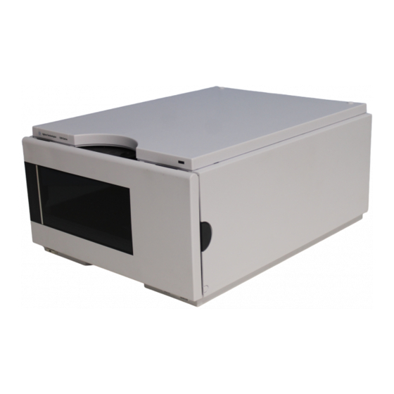
Introduction to the Well-plate Sampler Introduction to the Well-plate Sampler Four models of Agilent 1100 Series well-plate sampler are available: • G1367A Well-plate sampler • G1368A Thermostatted well-plate sampler • G1377A Micro well-plate sampler • G1378A Thermostatted micro well-plate sampler They are referred to in this introduction as the well-plate sampler and the thermostatted well-plate sampler. - Page 199 The injection valves from the G1367A/68A and the G1377A/78A have a different stator head and a different rotor seal. The volume of each valve is different.
-
Page 200: Sampling Sequence
Introduction to the Well-plate Sampler Sampling Sequence MTP board Sample transport Sampling unit Power supply Analytical head Vial tray Peristaltic pump Needle Switching valve Needle seat Figure 30 Overview of the well-plate sampler The movements of the well-plate sampler components during the sampling sequence are monitored continuously by the well-plate sampler processor. - Page 201 Introduction to the Well-plate Sampler The standard sampling sequence occurs in the following order: 1 The injection valve switches to the bypass position. 2 The plunger of the metering device moves to the initialization position. 3 The needle lock moves up. 4 The needle moves to the desired sample vial position.
-
Page 202: Injection Sequence
Introduction to the Well-plate Sampler Injection Sequence Before the start of the injection sequence, and during an analysis, the injection valve is in the mainpass position (Figure 31). In this position, the mobile phase flows through the well-plate sampler metering device, sample loop, and needle, ensuring all parts in contact with sample are flushed during the run, thus minimizing carry-over Figure 31... - Page 203 Introduction to the Well-plate Sampler The standard injection starts with „draw sample from vial”. In order to do this the needle moves to the desired sample vial position and is lowered into the sample liquid in the vial to allow the metering device to draw up the desired volume by moving its plunger back a certain distance.
-
Page 204: Sampling Unit
Introduction to the Well-plate Sampler Sampling Unit The sampling unit consists of subsystems as well. The main carrier part is a die casting part which carries the following functional elements. Analytical head The analytical head is driven by the stepper motor connected to the drive shaft by a toothed belt. -
Page 205: Injection-Valve
Introduction to the Well-plate Sampler Injection-Valve Table 56 Analytical head Technical Data Standard 100 µl Micro 40 µl (G1367-60003) (G1377-60013) Number of steps 15000 60000 Volume resolution 7 nl/motor step 0.7 nl/motor step Maximum stroke 100 µl 40 µl Pressure limit 400 bars 400 bars Plunger material... -
Page 206: Needle Flush Station
Introduction to the Well-plate Sampler Needle Flush Station Table 57 Injection-Valve Technical Data Standard (0101-0921) Micro (0101-1050) Motor type 4V, 1.2A stepper motor 4V, 1.2A stepper motor ™ ™ ™ Seal material Vespel or Tefzel Vespel Stator material Ceramic/PEEK Head coated SST Number of ports Switching time <... -
Page 207: Needle/Sample Transport Assembly
Introduction to the Well-plate Sampler Needle/Sample Transport Assembly Needle drive Needle lock Analytical head Flush port Peristaltic pump Needle seat Injection valve Figure 34 Well-plate sampler Sampling Unit The needle/sample transport is a multifunctional module capable of moving the needle into various positions (such as different wells in two different plates, different vials, needle wash position and the needle-seat position). - Page 208 Introduction to the Well-plate Sampler Reflective light switches detect the presence and type of different trays. The X-slide carries the antenna and electronics of a RF-sensor. This device has multiple functions: • It allows to read and write information from a tag, located in the new tray. •...
-
Page 209: Advanced Operating Modes
Introduction to the Well-plate Sampler Advanced Operating Modes Theta axis Needle carrier Z -axis X-axis Needle assembly Reflective light switches Figure 35 Needle/Sample Transport Assembly 1100 Series WS MWS Reference Manual... - Page 210 Introduction to the Well-plate Sampler Multi-draw mode (optional) The multi-draw mode provides injection volumes up to 1500 ul. In this case a capillary which holds the additional volume is assembled between seat and valve. Then the aspirated sample is pushed into the enlarged seat capillary before repetitive aspiration starts.
-
Page 211: Early Maintenance Feedback (Emf)
Introduction to the Well-plate Sampler Early Maintenance Feedback (EMF) Maintenance requires the exchange of components in the flow path which are subject to mechanical wear or stress. Ideally, the frequency at which components are exchanged should be based on the intensity of usage of the instrument and the analytical conditions, and not on a predefined time interval. -
Page 212: Using The Emf Counters
Introduction to the Well-plate Sampler Using the EMF Counters The user-setable EMF limits for the EMF counters enable the early maintenance feedback to be adapted to specific user requirements. The wear of autosampler components is dependent on the analytical conditions, therefore, the definition of the maximum limits need to be determined based on the specific operating conditions of the instrument. -
Page 213: Electrical Connections
Introduction to the Well-plate Sampler Electrical Connections Never use cables other than the ones supplied by Agilent Technologies to ensure WA RN ING proper functionality and compliance with safety or EMC regulations. CAN cable to previous module Vial number output... - Page 214 Introduction to the Well-plate Sampler 1100 Series WS MWS Reference Manual...
-
Page 215: Theory Of Operation
Agilent 1100 Series Well-plate Sampler & Micro Well-plate Sampler Reference Manual Theory of Operation Autosampler Control and Electronics Position and Movement Sensors Microtiter Plate Board (MTP) Firmware Description Optional Interface Boards Interfaces Setting the 8-bit Configuration Switch The Main Power Supply Assembly Agilent Technologies... -
Page 216: Autosampler Control And Electronics
Theory of Operation Autosampler Control and Electronics The Microtiter Plate Board (MTP) controls the vial-transport mechanism, sampling needle, metering unit, and high-speed injection valve. These devices are controlled by a versatile electronics design based upon a 68000 family processor which also contains battery backup RAM, flash ROM, a real time clock, and several communications options. -
Page 217: Position And Movement Sensors
Theory of Operation Position and Movement Sensors Position sensing of movement of well-plate sampler components is done by sensors on the sample transport and sampling unit flex boards. The following sensors are used: Table 58 Sample Transport Flex Board Sensor Type Number of Sensors Position/Movement Sensed Reflection Sensor... -
Page 218: Microtiter Plate Board (Mtp)
Theory of Operation Microtiter Plate Board (MTP) Common Electronics A common electronics and firmware design is used for all Agilent 1100 Series LC modules. This core design provides a basic set a functions for each module. Table 62 Common Electronics Core-processor MC68332 Core-memory... -
Page 219: Autosampler-Specific Electronics
Theory of Operation Fan Drive The fan speed (two speeds are possible) is controlled by the main processor according to the internal heat distribution inside the module. The fan provides a PWM signal which is proportional to the revolution. This fan status signal is used for diagnostics. - Page 220 Theory of Operation Transport Unit Control The transport drive electronics use current-controlled pulse-width modulation (PWM) to drive the X, Z, θ motors in closed-loop servo control mode. Dedicated electronics in the ST L6506 provide the current-control loop. Commutation is done in FPGA logic. The ST L6201 SMT output drivers are used for all three stepper motors.
- Page 221 Theory of Operation Sampling Unit Control Needle lock, metering device valve and peristaltic pump motors are driven by controlled pulse-width modulation in the same way as the ST L6506 (see “Transport Unit Control" on page 220). The motors require fast speed but do not require precise position control.
- Page 222 Theory of Operation Safety Lock Sensor Board (SLS) Two hall sensors detect correct closure of the front door (needle arm movement is interrupted, if front door is open). The front door is locked by an electric magnet. Unlocking the front door is done by pushing the button on the right side or switching the power off/on.
-
Page 223: Firmware Description
Theory of Operation Firmware Description The firmware of the instrument consists of two independent sections: • a non-instrument specific section, called ‘resident system’, • an instrument specific section, called ‘main system’. Resident System This resident section of the firmware is identical for all Agilent 1100 series modules. -
Page 224: Firmware Updates
Theory of Operation Firmware Updates Firmware updates can be done using your user interface: • handheld control module with files from a PC-card or • Agilent ChemStation with files from floppy disk The file naming conventions are: xxxx-vvv.DLB, where xxxx is the product number, e.g. 1367A for the well-plate sampler), and vvv is the revision number, for example 380 is revision 3.80 For instructions refer to your user interface. -
Page 225: Optional Interface Boards
Theory of Operation Optional Interface Boards The Agilent 1100 Series modules have one optional board slot that allows addition of an interface board to the modules. Table 63 Optional Interface Boards Description Part Number BCD Board G1351-68701 Fuse 250 mA (four are on the board) 2110-0004 LAN Board (see next page for details) BCD Board... - Page 226 Theory of Operation Pos. P2-A1=Vial 601 Vial 10 Pos. P2-B1= Vial 625 Plate 2 Pos. P2-P24= Vial 985 Pos. P1-A1= Vial 201 Pos. P1-B1= Vial 213 Plate 1 Pos. P1-H12= Vial 297 Vial 1 Figure 41 BCD output for the well plates Board identification Processor...
-
Page 227: Lan Board
Theory of Operation LAN Board The HP JetDirect cards are network interface cards used in HP printers. One board is required per Agilent 1100 stack. It is recommended to add the LAN board to NO TE the detector with highest data rate. The LAN board can only be used together with: NO TE a main board version G13XX-66520 (DAD/MWD/VWD/Pump/ALS) or... -
Page 228: Interfaces
For identification and location of the connectors Figure 5 on page 25. Never use cables other than the ones supplied by Agilent Technologies to ensure WA RN ING proper functionality and compliance with safety or EMC regulations. 1100 Series WS MWS Reference Manual... -
Page 229: Analog Signal Output
The GPIB connector is used to connect the module with a computer. The address and control switches next to the GPIB connector determine the GPIB address of your module. The switches are preset to a default address and recognized by the operating software from Agilent Technologies. Table 66 Default Addresses... -
Page 230: Remote Interface
Remote Interface The APG remote connector may be used in combination with other analytical instruments from Agilent Technologies if you want to use features such as common shut down, prepare, and so on. Remote control allows easy connection between single instruments or systems to ensure coordinated analysis with simple coupling requirements. -
Page 231: Rs-232C
Theory of Operation Table 67 Remote Signal Distribution (continued) Signal Description POWER ON (H) All modules connected to system are switched on. Receiver is any module relying on operation of others. READY (H) System is ready for next analysis. Receiver is any sequence controller. - Page 232 Theory of Operation Table 68 RS-232C Connection Table (continued) Direction Function Instrument Male Female Female Male Figure 43 RS-232 Cable 1100 Series WS MWS Reference Manual...
-
Page 233: Setting The 8-Bit Configuration Switch
Theory of Operation Setting the 8-bit Configuration Switch The 8-bit configuration switch is located next to the GPIB connector. Switch settings provide configuration parameters for GPIB address, serial communication protocol and instrument specific initialization procedures. Figure 44 8-bit Configuration Switch Table 69 8-bit Configuration Switch Mode Select... -
Page 234: Gpib Default Addresses
Theory of Operation In this way you can store more than one set of parameters using the same 8-bit configuration switch twice, for example, for both GPIB and RS-232C. GPIB Default Addresses If you just want to change the GPIB address and need a detailed procedure, refer to the Installing Your Agilent ChemStation System handbook. -
Page 235: Communication Settings For Rs-232C Communication
Theory of Operation Communication Settings for RS-232C Communication The communication protocol used in this instrument supports only hardware handshake (CTS/RTS). Switches 1 in down and 2 in up position define that the RS-232C parameters will be changed. Once the change has been completed, the instrument must be powered up again in order to store the values in the non-volatile memory. -
Page 236: Forced Cold Start Settings
Theory of Operation Table 74 Parity Settings Switches Parity No Parity Odd Parity Even Parity One start bit and one stop bit are always used (not selectable). Per default, the module will turn into 19200 baud, 8 data bit with no parity. Forced Cold Start Settings Switches 1 and 2 do not force storage of this set of parameters in non-volatile memory. -
Page 237: Stay-Resident Settings
Theory of Operation Stay-Resident Settings Firmware update procedures may require this mode in case of firmware loading errors. Switches 1 and 2 do not force storage of this set of parameters in non-volatile memory. Returning switches 1 and 2 to other positions (other than being both up) will allow for normal operation. -
Page 238: The Main Power Supply Assembly
Theory of Operation The Main Power Supply Assembly The main power supply comprises a closed assembly (no on site repair possibility). The power supply provides all DC voltages used in the module except for the voltages supplied by the lamp power supply to the deuterium and tungsten lamps in the detectors. - Page 239 Theory of Operation No accessible hardware fuse is needed because the main power supply is safe against any short circuits or overload conditions on the output lines. When overload conditions occur, the power supply turns off all output voltages. Turning the line power off and on again resets the power supply to normal operation if the cause of the overload condition has been removed.
- Page 240 Theory of Operation 1100 Series WS MWS Reference Manual...
-
Page 241: 8 Control Module Screens Of The Well-Plate Samplers
Agilent 1100 Series Well-plate Sampler & Micro Well-plate Sampler Reference Manual Control Module Screens of the Well-plate Samplers Major keys on the Agilent 1100 Control Module Screens available from the Analysis view Screens available from the System view Agilent Technologies... -
Page 242: Major Keys On The Agilent 1100 Control Module
Control Module Screens of the Well-plate Samplers Major keys on the Agilent 1100 Control Module Table 78 Return to previous screen, abort any change of parameters and toggle between the last two top layer views Open context sensitive menus Information/Help Enter Store changed parameters or execute a choice Done... -
Page 243: Screens Available From The Analysis View
Control Module Screens of the Well-plate Samplers Screens available from the Analysis view Analysis view This is the wake-up screen, if the Agilent 1100 Series well-plate samplers or micro well-plate samplers are the only configured Agilent 1100 module. It is used to enter the most common WPS method parameters. - Page 244 Control Module Screens of the Well-plate Samplers The m-key allows access to the context sensitive menus. Date&Time allows you to change time settings. Print Screen gives access to the print screen. About tells you the current firmware revision and the serial# of your control module.
- Page 245 Control Module Screens of the Well-plate Samplers In the Setup view, modules can be added or removed to the analysis view. Select a module, you want to move, with the help of the selection-keys. Use function keys F7/F8 (Remove/Add) to move the highlighted module. Changes must be activated with Done (F6).
- Page 246 Control Module Screens of the Well-plate Samplers The m-key gives access to a context sensitive menu (related to the module that is highlighted by the cursor, like in this case the WPS). With the F1-key (Settings) you open a pull-down menu where you can select the WPS module.
- Page 247 Control Module Screens of the Well-plate Samplers Settings Within Settings you can change the WPS parameters like the Injection Volume. You can toggle between Standard Injection (with/without needle wash) and Injector Program. There are different sets of parameters available through the F1-5 navigation-keys for optimizing the operation of the WPS.
- Page 248 Control Module Screens of the Well-plate Samplers Use the m-key for the context sensitive menu. The Status command pulls up a module specific screen displaying details of injections and the well-plate trays. Reset will initialize the well-plate sampler. The F1-key (More) opens a pull-down menu. 1100 Series WS MWS Reference Manual...
- Page 249 Control Module Screens of the Well-plate Samplers Settings More... By selecting More...Settings on the pull-down menu you can enter WPS set points for the Draw Speed, Eject Speed and Draw Position Offset. Changes must be acknowledged with F6 (Done). By selecting More...Needle Wash on the pull-down menu you can specify the time period for inserting the needle into the flush port or define how often the needle is dipped into a specified wash vial.
- Page 250 Control Module Screens of the Well-plate Samplers By selecting More...Auxiliary on the pull-down menu you can specify an Equilibration Time after drawing and before injecting and you can enable/disable the Vial / Well Bottom Sensing. Changes must be acknowledged with F6 (Done). By selecting More...High Throughput on the pull-down menu you can enter different optimization modes like the ‘Automatic Delay Volume Reduction’...
- Page 251 Control Module Screens of the Well-plate Samplers Press ‘F1’ (Link Pump) to get access the screen, that allows you to choose one of the pumps (if multiple pumps are configured), which will then be used for the calculation of the flushout time of the sampler (depending on flow rate and internal volume of the sampler).
- Page 252 Control Module Screens of the Well-plate Samplers Settings - Timetable With the F2-key (Timetable) you can list the timetable for the WPS. Press F7-key (Insert) to edit the selected entry or F6-key (Delete) to remove the selected/highlighted entry. Edit each entry line according to your needs, by entering a time for a Setting and by selecting a Setting with the help of the pull-down menu.
- Page 253 Control Module Screens of the Well-plate Samplers Settings - Injection Program With the F3-key (Inj. Program) you can change the settings for the analog outputs. Press the F7-key (Enter) to add program events. Use the F6-key (Done) to view the entered lines of the timetable. Use the m-key for the context sensitive menu.
- Page 254 Control Module Screens of the Well-plate Samplers Settings - Thermostat With the F4-key (Thermostat) you can set the well-plate sampler thermostat temperature. Changes must be acknowledged with F6 (Done). Settings - Run times With the F5-key (Runtimes) you can change the stop time and the post-run time for the selected module individually.
- Page 255 Control Module Screens of the Well-plate Samplers Status From the Analysis View press the F5-key (Views) and select Status. This is an example if an Agilent 1100 WPS is configured stand-alone. Signal plot Press F6-key (Plot) to enter the plot screen (available also from all other screens).
- Page 256 Control Module Screens of the Well-plate Samplers Press the m-key to open the context sensitive menu. Press F6-key (Select). Here you can add additional on-line signals (maximum are 3). Additional signals could be also pressure or temperature signals from other modules. Use the Right/Left selection keys to switch between ‘Available Signals’...
- Page 257 Control Module Screens of the Well-plate Samplers Method screens Use Esc to return to the Analysis screen. Use the F3-key (Method) to view the parameters in a method. Use the F8-key (Save As) to save the method in the mdodule(s). The PC-Card-key is only active when a PCMCIA card is inserted in the control module.
- Page 258 Control Module Screens of the Well-plate Samplers Use the Right/Left selection keys to switch between PC-Card and Instrument window.Use the Up/Down selection keys to select the method. Use F7/F8 (Copy) to copy a selected method from one window to the other one. Use F6 (Delete) to delete a selected method.
-
Page 259: Screens Available From The System View
Control Module Screens of the Well-plate Samplers Screens available from the System view System view Use the Esc-key until you receive Views on the F5-key. Choose System from the pull-down menu. This screen shows the last activities in the system. 1100 Series WS MWS Reference Manual... - Page 260 Control Module Screens of the Well-plate Samplers System - Control Use the F1-key (Control) to select the well-plate Sampler. Here you receive information about the not-Ready conditions, if needed. F7 (Reset) does a re-initialization of the WPS. Use the F8-key (On/Off) to turn on the thermostat.
- Page 261 Control Module Screens of the Well-plate Samplers System - Configuration Use the Esc-key to receive Views on the F5-key in the Analysis Screen. Choose System from the pull-down menu. Use the F2-key (Configure) to select the WPS. Here you define further special set points for the WPS operation. Changes must be acknowledged with F6 (Done).
- Page 262 Control Module Screens of the Well-plate Samplers Configure - Trays Use the F2-key (Trays) to view and configure the detected sample trays. Select/highlight a tray configuration with the help of the selection keys. F7/F8 (Add/Remove) allows you to move configurations from available Plate Formats to the Active Plates and vice versa.
- Page 263 Control Module Screens of the Well-plate Samplers Configure - Volumes F3 (Volumes) in the main Configuration screen allows you to configure the volumes of the seat capillary and the loop capillary. Changes must be acknowledged with F6 (Done). Configure - Thermostat F4 (Therm) in the main Configuration screen allows you to configure the temperature and turn on conditions of the thermostatted WPS.
- Page 264 Control Module Screens of the Well-plate Samplers System - Tests Press F3 from the System View and choose the WPS to access the WPS Tests screen. The Tests screen gives you access to multiple tests and features such as the automatic transport unit Alignment tool,maintenance procedures to Change parts on the WPS or additional test Signals to monitor various parameters during the WPS operation.
- Page 265 Control Module Screens of the Well-plate Samplers The alignment process may take several minutes. Changes must be acknowledged with F6 (Done). Use the F2-key (Change) to access maintenance positions for changing the Needle or sample Loop, the Piston of the metering drive or the transport unit Arm.
- Page 266 Control Module Screens of the Well-plate Samplers Press F3 (Signals) in the Tests screen to access additional service signal for diagnosing and troubleshooting the WPS. Here you can monitor various temperatures inside the module 1100 Series WS MWS Reference Manual...
- Page 267 Control Module Screens of the Well-plate Samplers EMF (Early Maintenance Feedback) Use the F1-key (EMF) to set EMF limits. Choose Setup limits to select the number of injection valve cycles or number of needle movements into the needle seat at which you want to receive a warning. Changes must be acknowledged with F6 (Done).
- Page 268 Control Module Screens of the Well-plate Samplers System / Error Log Use the F2-key (System Log) or F3-key (Error Log) to look for errors. For troubleshooting reasons these Logbooks can be printed or saved to a file on the PCMCIA card (pressing the m-key). 1100 Series WS MWS Reference Manual...
- Page 269 Control Module Screens of the Well-plate Samplers Maintenance Log Use the F4-key (Maintenance Log) to look for maintenance activities performed on the instrument. A list of possible events are listed in the scroll screen. Select the activity you have performed and press Done to create an entry in the logbook.
- Page 270 Control Module Screens of the Well-plate Samplers Use the Esc-key to receive Views on the F5-key. Choose System from the pull-down menu. Use the F3-key (Records) to select the WPS. Use the F5-key (FW Update) to enter the Update section. Select the a file from the PCMCIA card (1367nnnn.DLB for the non-thermostatted WPS or 1368nnnn.DLB for the thermostatted WPS, use 1377nnnn.DLB for the non-thermostatted micro WPS or 1378nnnn.DLB for the thermostatted micro WPS) and press execute.
- Page 271 Control Module Screens of the Well-plate Samplers If you have not saved your methods, please do it before continuing. Otherwise they will be overwritten during the update process. Changing the serial number In case the serial number of the module has to be added, use the m-key to open the menu Enter Serial#.
- Page 272 Control Module Screens of the Well-plate Samplers Type in the module’s Serial# as indicated on the front or rear label of the module using the alphanumeric keys. Changes must be acknowledged with F6 (Done). 1100 Series WS MWS Reference Manual...
-
Page 273: 9 Specifications
Agilent 1100 Series Well-plate Sampler & Micro Well-plate Sampler Reference Manual Specifications Performance Specifications Agilent Technologies... -
Page 274: Performance Specifications
Specifications Performance Specifications Table 79 Performance Specifications Agilent 1100 Series Well Plate Sampler Type Specification GLP features Early maintenance feedback (EMF), electronic records of maintenance and errors Communications Controller-area network (CAN). RS232C, APG-remote standard, optional four external contact closures and BCD vial number output Safety features Leak detection and safe leak handling, low voltages in maintenance areas, error detection and display... - Page 275 Specifications Table 80 Performance Specifications Agilent 1100 Series Micro Well Plate Sampler Type Specification GLP features Early maintenance feedback (EMF), electronic records of maintenance and errors Communications Controller-area network (CAN). RS232C, APG-remote standard, optional four external contact closures and BCD vial number output Safety features Leak detection and safe leak handling, low voltages in maintenance areas, error detection and display...
- Page 276 Specifications 1100 Series WS MWS Reference Manual...
-
Page 277: A Safety Information
Agilent 1100 Series Well-plate Sampler & Micro Well-plate Sampler Reference Manual Safety Information General Safety Information Agilent Technologies... -
Page 278: General Safety Information
Safety Information General Safety Information The following general safety precautions must be observed during all phases of operation, service, and repair of this instrument. Failure to comply with these precautions or with specific warnings elsewhere in this manual violates safety standards of design, manufacture, and intended use of the instrument. - Page 279 Safety Information Table 81 Safety Symbols Symbol Description The apparatus is marked with this symbol when the user should refer to the instruction manual in order to prevent risk of harm to the operator and to protect the apparatus against damage. Indicates dangerous voltages.
- Page 280 Safety Information Lithiumbatteri - Eksplosionsfare ved fejlagtic handtering. Udskiftning ma kun ske WA RN ING med batteri af samme fabrikat og type. Lever det brugte batteri tilbage til leverandoren. Lithiumbatteri - Eksplosionsfare. Ved udskiftning benyttes kun batteri som anbefalt WA RN ING av apparatfabrikanten.
- Page 281 Index condensation, setting, configuration switch, using, address switch, control module environment, 14, advanced operating modes, Analysis screens, error messages, 56, Agilent on internet, Config screens, arm movement, air circulation, Control screens, compensation sensor open, analog signal output, Error Log screen, compensation sensor short, Analytical, Firmware Update screens,...
- Page 282 Index interface board, cover parts, LAN cables, foam parts, GPIB LAN interface board, injection valve assembly, default addresses, low volume injections, injection-valve assembly, interface, low-volume capillary kit, leak system parts, maintenance kit, multi-draw kit, power and status light pipes, half trays, main board, sampling unit assembly, half-tray combinations,...
- Page 283 Index SUD board, top cover and foam, unpacking the autosampler, transport assembly, using the ESD strap, rotor seal, 53, RS-232 valve capillaries, cable kit to PC, Vespel, RS-232C vial contents temperature, communication settings, vial numbering, interface, vial racks, settings, vial tray, vials, viscous samples, 51, safety information...
- Page 284 Index 1100 Series WS MWS Reference Manual...
- Page 286 In This Book This manual contains technical reference information about the Agilent 1100 Series Well-plate Sampler & Micro Well-plate Sampler and micro well plate sampler. The manual describes the following: • installing the sampler, • optimizing performance, • troubleshooting and test functions, •...