Table of Contents
Advertisement
Available languages
Available languages
Quick Links
ITA/ENG
rev.5 26/03/2020
LEVEL
SA612.xx / SA615.xx
MANUALE DI ISTRUZIONE E INSTALLAZIONE
INSTRUCTION AND INSTALLATION MANUAL
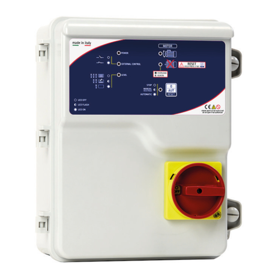
Quadro elettrico avviamento diretto 1 motore per il controllo della marcia a secco (sonde)
con sezionatore blocca porta.
Direct starting electronic control panel 1 motor for the dry running control (probes) with
general disconnecting switch with door lock.
CUSTOMER SERVICE
customer.service@salupoquadri.com
( )
+39 0 941.1820216
Advertisement
Table of Contents

Related Manuals for SALUPO Level


Summary of Contents for SALUPO Level
- Page 1 ITA/ENG rev.5 26/03/2020 LEVEL SA612.xx / SA615.xx MANUALE DI ISTRUZIONE E INSTALLAZIONE INSTRUCTION AND INSTALLATION MANUAL Quadro elettrico avviamento diretto 1 motore per il controllo della marcia a secco (sonde) con sezionatore blocca porta. Direct starting electronic control panel 1 motor for the dry running control (probes) with general disconnecting switch with door lock.
-
Page 2: Table Of Contents
INDICE 1. Istruzioni generali per l’installazione 2. Avvertenze 3. Schemi di collegamento 3.1 Schema di collegamento SA612.xx 3.2 Schema di collegamento SA615.xx 4. Esempi applicativi 5. Programmazione 5.1 Impostazione DIP-SWITCH 5.2 Regolazione trimmer 6. Funzionamento generale del quadro 7. Ricerca guasti e soluzioni proposte 8. -
Page 3: Istruzioni Generali Per L'installazione
1. ISTRUZIONI GENERALI PER L’INSTALLAZIONE ITALIANO Assicurarsi che la linea sia protetta, secondo le normative, in funzione dell'applicazione. Accertarsi che la potenza e la corrente di targa del motore rispecchino i limiti di impiego del quadro. Installare il quadro in ambienti adatti al suo grado di protezione IP65. Per il fissaggio dell'involucro, utilizzare le staffe per i box 03-04 e le apposite predisposizioni per i restanti box. -
Page 4: Schemi Di Collegamento
3. SCHEMI DI COLLEGAMENTO 3.1 Schema di collegamento SA612.xx CURRENT MOTOR 1 PROBE SENSITIVITY PROBE DELAY COLLEGAMENTO CON GALLEGGIANTE 3 4 5 6 1 2 3 4 G.MIN G.MAX1 G.MAX2 AVV. PR.STA MOTORE CONDENSATORE MOTORE LINEA DI ALIMENTAZIONE 230 Vac 50/60 Hz LEGENDA SONDA COMUNE SONDA MINIMO... -
Page 5: Schema Di Collegamento Sa615
3. SCHEMI DI COLLEGAMENTO ITALIANO 3.2 Schema di collegamento SA615.xx CURRENT MOTOR 1 PROBE SENSITIVITY PROBE DELAY COLLEGAMENTO CON GALLEGGIANTE 3 4 5 6 1 2 3 4 G.MIN G.MAX1 G.MAX2 PR.STA MOT1 SUPPLY LINEA DI ALIMENTAZIONE 400 Vac 50/60 Hz MOTORE LEGENDA SONDA COMUNE... -
Page 6: Esempi Applicativi
4. ESEMPI APPLICATIVI Di seguito vengono illustrati alcuni esempi pratici delle applicazioni che è possibile realizzare con il quadro LEVEL. ACQUE PULITE (RIEMPIMENTO) ACQUE PULITE (SVUOTAMENTO) SONDA MAX TEMPORIZZATA START/ START/ STOP STOP START/ STOP START/ STOP G.MIN LEGENDA COMPONENTI... -
Page 7: Programmazione
5. PROGRAMMAZIONE 5. PROGRAMMAZIONE ITALIANO 5.1 Impostazioni DIP-SWITCH CONFIGURAZIONE DI DEFAULT 1 2 3 4 APPLICAZIONE ACQUE PULITE 1 2 3 4 1 2 3 4 Svuotamento Riempimento ATTIVA SONDA TEMPORIZZATA 1 2 3 4 1 2 3 4 Attiva Disattiva PROTEZIONE MINIMA E MASSIMA TENSIONE 1 2 3 4... -
Page 8: Funzionamento Generale Del Quadro
6. FUNZIONAMENTO GENERALE DEL QUADRO ACCENSIONE QUADRO ATTESA 10s PRESENZA RETE VALORE DI TENSIONE MISURATO È AL DI FUORI DELLA SOGLIA CONSENTITA MANCANZA O ERRATA SEQUENZA FASE INDICA CHE IL MOTORE È IN FUNZIONE INDICA CHE IL MOTORE È SPENTO INDICA UN ALLARME DI SOVRACCARICO DEL MOTORE CHE NE CAUSA LO SPEGNIMENTO FUNZIONAMENTO MANUALE: SI ATTIVA DALLO STATO STOP TENENDO PREMUTO IL PULSANTE. -
Page 9: Ricerca Guasti E Soluzioni Proposte
(SA612.xx) collegarlo correttamente Jumper su R (riempimento) Impostare il jumper su S (svuotamento) Aumentare la sensibilità delle sonde Led LEVEL ON Conduttività del liquido nella scheda madre con il pozzo pieno Verificare la funzionalità delle sonde Rottura di una o più sonde... - Page 10 INDEX 1. General instructions for installing 2. Warnings 3. Wiring diagrams 3.1 Wiring diagrams SA612.xx 3.2 Wiring diagrams SA615.xx 4. Application examples 5. Programming DIP-SWITCH setting 2 Trimmer adjustment 6. General functioning of the control panel 7. Troubleshooting and proposed solutions 8.
- Page 11 1. GENERAL INSTRUCTIONS FOR INSTALLING ENGLISH Make sure power supply is protected up to standard depending on application. The power of the motor has to be within the control panel's limits of use. Install the control panel in an environment appropriate to its IP65 degree of protection. To fix the enclosure, use the brackets for the boxes 03-04 and the special predispositions for the remaining boxes.
- Page 12 3. WIRING DIAGRAM 3.1 Wiring diagram SA612.xx CURRENT MOTOR 1 PROBE SENSITIVITY PROBE DELAY CONNECTION WITH WITH FLOAT SWITCH 3 4 5 6 1 2 3 4 G.MIN G.MAX1 G.MAX2 AVV. PR.STA MOTOR CAPACITOR MOTOR POWER SUPPLY 230 Vac 50/60 Hz COMMON PROBE MINIMUM PROBE MAXIMUM PROBE...
- Page 13 3. WIRING DIAGRAM ENGLISH 3.2 Wiring diagram SA615.xx CURRENT MOTOR 1 PROBE SENSITIVITY PROBE DELAY CONNECTION WITH WITH FLOAT SWITCH 3 4 5 6 1 2 3 4 G.MIN G.MAX1 G.MAX2 PR.STA MOT1 SUPPLY POWER SUPPLY 400 Vac 50/60 Hz MOTOR COMMON PROBE MINIMUM PROBE...
- Page 14 4. APPLICATION EXAMPLES Below are some practical examples of applications that can be implemented with the LEVEL control panel. CLEAN WATER (FILLING) CLEAN WATER (EMPTYING) - 1 INPUT TIMED POBE MAX START/ START/ STOP STOP START/ STOP START/ STOP G.MIN...
- Page 15 (the red PROTECTION Led lights up) and then increase the regulation by 20%. Through this trimmer it is possible to set the sensitivity of the conductivity between the 3 level probes. The adjustment range is from 0 to 100 Kohm. PROBE SENSITIVITY...
- Page 16 EMPTYING MAX 2 FLOAT SWITCH ON, THE MOTOR IS ENABLED NO WATER (UNCOVERED MINIMUM LEVEL), THE MOTOR IS DISABLED WAITING FILLING, THE MOTOR IS DISABLED N.B.: THE MOTOR STARTS ONLY IF IT IS IN AUTOMATIC OPERATION AND STOPS ONLY WHEN THE MAX 2 FLOAT...
- Page 17 Jumper on R (filling) Set the jumper on S (emptying) Increase the sensitivity of the probes on the Led LEVEL ON with Conductivity of the liquid motherboard water in the well Check the functionality of the probes...
-
Page 18: Smaltimento Di Vecchi Apparecchi Elettrici Ed Elettronici
98070 Torrenova (ME) Dichiara che: gli avviatori diretti LEVEL Monofase e Trifase sono conformi ai requisiti di protezione in materia di sicurezza (bassa tensione) e di compatibilità elettromagnetica specifici previsti dalle Direttive della Comunità Europea 2006/95/CEE del 16 Gennaio 2007, 2004/108/CE del 10 Novembre 2007, 93/68/CEE del 22 Luglio 1993. -
Page 19: Certificato Di Garanzia
Dear customer, Salupo S.r.l. would like to thank you for your preference. The product you have purchased is covered by the warranty as shown below. We guarantee the quality and smooth operation of our products up to 24 months, starting from the date of purchase, against manufacturing defects and except for the following items for which we guarantee up to 12 months: SQ702.xx;... - Page 20 C/da Pietra di Roma Via Vicolo VI, n°2 98070 Torrenova (ME) ITALY Tel.:+39 - 0941 - 950216 Fax:+39 - 0941 - 958777 www.salupoquadri.com e-mail: info@salupoquadri.com...
Need help?
Do you have a question about the Level and is the answer not in the manual?
Questions and answers