Table of Contents
Advertisement
Quick Links
CODE
SA682/685.xx
MANUALE DI ISTRUZIONE E INSTALLAZIONE
INSTRUCTION AND INSTALLATION MANUAL
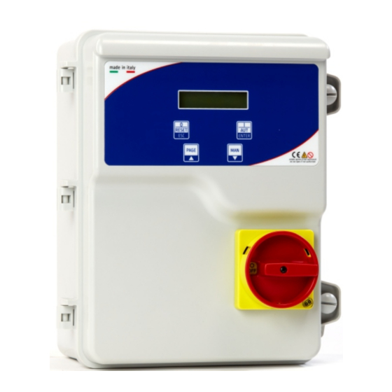
Avviatori Diretti per 1 elettropompa, con protezione amperometrica, controllo di livello,
mancanza e sequenza fasi (Trifase), display a cristalli liquidi e sezionatore blocca porta.
Direct starters (for 1 electric pump) with amperometric protection, level control, lack and
sequence of phase (Three-phase), liquid crystal display and general disconnecting
switch with door lock.
ITA/ENG
AVVIATORI RAIN PLUS 1
RAIN PLUS 1 STARTERS
REV. 3
06/05/2019
MADE IN ITALY
Advertisement
Table of Contents

Subscribe to Our Youtube Channel
Related Manuals for SALUPO RAIN PLUS 1


Summary of Contents for SALUPO RAIN PLUS 1
- Page 1 CODE REV. 3 SA682/685.xx 06/05/2019 AVVIATORI RAIN PLUS 1 RAIN PLUS 1 STARTERS MANUALE DI ISTRUZIONE E INSTALLAZIONE INSTRUCTION AND INSTALLATION MANUAL Avviatori Diretti per 1 elettropompa, con protezione amperometrica, controllo di livello, mancanza e sequenza fasi (Trifase), display a cristalli liquidi e sezionatore blocca porta.
-
Page 2: Table Of Contents
INDICE INDEX 1. Istruzioni generali per l’installazione....General instructions for installing....3 2. Avvertenze............Warnings............4 3. Caratteristiche generali ........General characteristics........5 4. Caratteristiche elettriche e meccaniche..... Electrical and mechanical characteristics..6 5. Schema di collegamento SA682.00....Wiring diagram SA682.00.......7 6. Schema di collegamento SA685.xx....Wiring diagram SA685.xx.......8 7. -
Page 3: General Instructions For Installing
1. ISTRUZIONI GENERALI PER L’INSTALLAZIONE 1. GENERAL INSTRUCTIONS FOR INSTALLING Assicurarsi che la linea sia protetta, secondo le Make sure power supply is protected up to normative, in funzione dell'applicazione. standard depending on application. The power Accertarsi che la potenza e la corrente di targa of the motor has to be within the control panel's del motore rispecchino i limiti di impiego del limits of use. -
Page 4: Warnings
2. AVVERTENZE 2. WARNINGS SCOSSE ELETTRICHE ELECTRIC SHOCKS Rischio di scosse elettriche se non osservate quanto Risk of electric shocks if not complied with the prescritto. requirements. DANGER PERICOLO Risk of personal injury and property if not complied Rischio di danni alle persone, e alle cose se non with the requirements. -
Page 5: General Characteristics
3. CARATTERISTICHE GENERALI 3. GENERAL CHARACTERISTICS - Tensione d'alimentazione 230 Vac ± 10% - Power supply 230 Vac ± 10% (SA682.xx) (SA682.xx) - Power supply 400 Vac ± 10% (SA685.xx) - Tensione d'alimentazione 400 Vac ± 10% - Operating frequency 50Hz (SA685.xx) - General disconnecting switch with door lock - Frequenza di lavoro 50Hz... -
Page 6: Electrical And Mechanical Characteristics
4. CARATTERISTICHE ELETTRICHE E MECCANICHE 4. ELECTRICAL AND MECHANICAL CHARACTERISTICS SINGLE-PHASE CODE OPERATING DIMENSIONS POWER WEIGHT CURRENT 2-18 SA682.00 0,37/2,2 0,5/3 THREE-PHASE OPERATING CODE POWER DIMENSIONS WEIGHT CURRENT 0,8-9 0,5/5 SA685.00 0,37/3,7 SA685.01 0,37/5 0,5/7 0,8-12 SA685.02 0,37/6,5 0,5/9 0,8-16 4-25 3/12,5 SA685.03... -
Page 7: Wiring Diagram Sa682.00
5. SCHEMA DI COLLEGAMENTO SA682.xx 5. WIRING DIAGRAM SA682.xx SENSORE PIOGGIA OPZIONALE 1 2 3 4 3 4 5 6 9 10 11 G.MIN G.MAX1 G.MAX2 AVV. PR.STA MOTOR 1 ALARM MOTORE LEGENDA SONDE DI LIVELLO O GALLEGGIANTE MINIMO SONDE DI LIVELLO O GALLEGGIANTE MAX1 LINEA DI ALIMENTAZIONE CONTATTO SENSORE PIOGGIA 230 Vac 50/60 Hz... -
Page 8: Wiring Diagram Sa685.Xx
6. SCHEMA DI COLLEGAMENTO SA685.xx 6. WIRING DIAGRAM SA685.xx SENSORE PIOGGIA OPZIONALE 1 2 3 4 9 10 11 3 4 5 6 G.MIN G.MAX1 G.MAX2 PR.STA MOT1 SUPPLY ALARM LINEA DI ALIMENTAZIONE 400 Vac 50/60 Hz MOTORE LEGENDA SONDE DI LIVELLO O GALLEGGIANTE MINIMO SONDE DI LIVELLO O GALLEGGIANTE MAX1 CONTATTO SENSORE PIOGGIA KLIXON MOTORE... -
Page 9: Menu And Buttons
9. MENU E PULSANTI 9. MENU AND BUTTONS Il RAIN PLUS ha 2 tipi di menu, SETUP e The LEVEL PLUS has two types of menu, FUNZIONAMENTO. SETUP and OPERATION. Il primo viene utilizzato solo per eseguire la The first one is only used for programming, the programmazione, il secondo per gestire e far second one to manage and operate the pump. -
Page 10: Programming
10. PROGRAMMAZIONE 10. PROGRAMMING Accendere il quadro ed entro il tempo di Turn the control panel on and enter the setup ATTESA PRESENZA RETE (10 s) entrare nel within the SUPPLY MAINS WAIT time (10 s) by setup premendo contemporaneamente per 2 s pressing both the + and - buttons for 2 s. -
Page 11: Minimum And Maximum Voltage
SCHERMATA DESCRIZIONE RANGE DEFAULT SCREEN DESCRIPTION Serve a impostare una protezione sulla tensione minima in ingresso OFF / 180-220V TENSIONE MINIMA (vedi cap. 10.1) (SA682.xx) It serves to set a protection on the minimum voltage input OFF / 330-380V MINIMUM VOLTAGE (See chap. -
Page 12: General Functioning Of The Control Panel
11. FUNZIONAMENTO GENERALE DEL QUADRO 11. GENERAL FUNCTIONING OF THE CONTROL PANEL All’accensione del dispositivo il display si When you turn the device on, the display lights illumina e riporta la seguente schermata. up and shows the following screen. PRESENZA RETE ATTESA 10 s Superato il tempo di ATTESA PRESENZA Passed the SUPPLY MAINS WAIT time the... - Page 13 Nella quarta schermata sarà possibile In the fourth screen it will be possible to visualizzare due diversi messaggi in funzione visualize two different messages according to dello stato della vasca: the status of the tank: Nel caso in cui il livello dell’acqua nella vasca di If the level of the water in the collecting tank raccolta si trovasse al di sotto della sonda di were under the MAXIMUM probe it will be...
-
Page 14: Alarm Messages
12. MESSAGGI DI ALLARME 12. ALARM MESSAGES DESCRIZIONE SCHERMATA DESCRIPTION SCREEN Se la corrente assorbita dal motore dovesse superare quella impostata nel setup il display ALLARME CORRENTE visualizzerà il seguente messaggio MASSIMA If the current absorbed by the motor exceeds that adjusted in the setup the display will show the MAXIMUM CURRENT following message ALARM... -
Page 15: Troubleshooting And Proposed Solutions
13. RICERCA GUASTI E SOLUZIONI PROPOSTE 13. TROUBLESHOOTING AND PROPOSED SOLUTIONS PROBLEMI COMUNI POSSIBILI CAUSE SOLUZIONI FREQUENT PROBLEMS CAUSES OPERATION Alimentare il quadro rispettando Alimentazione di rete Off la tensione di ingresso Feed the plant respecting o supply the input voltage Manopola del sezionatore su 0 Posizionare la manopola del sezionatore su 1 Il display non si accende... -
Page 16: Declaration Of Conformity
98070 Rocca di Capri Leone (ME) 98070 Rocca di Capri Leone (ME) Dichiara che: Declares that: gli avviatori diretti RAIN PLUS 1 Monofase e the Single-phase and Three-phase RAIN Trifase PLUS 1 direct starters sono conformi ai requisiti di protezione in... - Page 20 SALUPO Via Laganeto, 129 98070 Rocca di Caprileone (ME) ITALY Tel.:+39 - (0) 941 - 950216 Fax:+39 - (0) 941 - 958777 www.salupoquadri.com e-mail: salupo@salupoquadri.com UNI EN ISO 9001:2008...
Need help?
Do you have a question about the RAIN PLUS 1 and is the answer not in the manual?
Questions and answers