Table of Contents
Advertisement
Available languages
Available languages
Quick Links
rev.4 26/03/2020
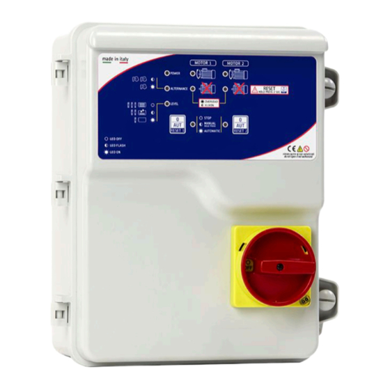
DUAL MOTOR
SA623.xx / SA626.xx
MANUALE DI ISTRUZIONE E INSTALLAZIONE
INSTRUCTION AND INSTALLATION MANUAL
Quadro elettronico avviamento diretto 2 motori per pressurizzazione con sezionatore
blocca porta.
Direct starting electronic control panel 2 motors for pressurization with general
disconnecting switch with door lock.
CUSTOMER SERVICE
customer.service@salupoquadri.com
( )
+39 0 941.1820216
Advertisement
Table of Contents

Related Manuals for SALUPO SA623 Series


Summary of Contents for SALUPO SA623 Series
- Page 1 rev.4 26/03/2020 DUAL MOTOR SA623.xx / SA626.xx MANUALE DI ISTRUZIONE E INSTALLAZIONE INSTRUCTION AND INSTALLATION MANUAL Quadro elettronico avviamento diretto 2 motori per pressurizzazione con sezionatore blocca porta. Direct starting electronic control panel 2 motors for pressurization with general disconnecting switch with door lock. CUSTOMER SERVICE customer.service@salupoquadri.com +39 0 941.1820216...
-
Page 2: Table Of Contents
INDICE 1. Istruzioni generali per l’installazione.....................3 2. Avvertenze............................3 3. Schemi di collegamento 3.1 Schema di collegamento SA623.xx..................4 3.2 Schema di collegamento SA626.xx..................5 4. Esempi applicativi.........................6 5. Programmazione 5.1 Impostazione DIP-SWITCH....................7 5.2 Regolazione trimmer ......................7 6. Funzionamento generale del quadro....................8 7. -
Page 3: Istruzioni Generali Per L'installazione
1. ISTRUZIONI GENERALI PER L’INSTALLAZIONE ITALIANO Assicurarsi che la linea sia protetta, secondo le normative, in funzione dell'applicazione. Accertarsi che la potenza e la corrente di targa del motore rispecchino i limiti di impiego del quadro. Installare il quadro in ambienti adatti al suo grado di protezione IP65. Per il fissaggio dell'involucro, utilizzare le staffe per i box 03-04 e le apposite predisposizioni per i restanti box. -
Page 4: Schemi Di Collegamento
3. SCHEMI DI COLLEGAMENTO 3.1 Schema di collegamento SA623.xx CURRENT MOTOR 1 CURRENT MOTOR 2 CAPACITOR M1 COLLEGAMENTO CON GALLEGGIANTE 3 4 5 6 7 8 1 2 3 4 CAPACITOR M2 G.MIN G.MAX1 G.MAX2 G.ALAR AVV. AVV. PR.STA PR.EME MOTOR 1 MOTOR 2 MOTORE 1... -
Page 5: Schema Di Collegamento Sa626.Xx
3. SCHEMI DI COLLEGAMENTO ITALIANO 3.2 Schema di collegamento SA626.xx CURRENT MOTOR 1 CURRENT MOTOR 2 3 4 5 6 7 8 G.MIN G.MAX1 G.MAX2 G.ALAR PR.STA PR.EME MOT1 MOT2 SUPPLY G.MIN G.MAX1 LINEA DI ALIMENTAZIONE 400 Vac 50/60 Hz MOTORE 1 MOTORE 2 LEGENDA... -
Page 6: Esempi Applicativi
4. ESEMPI APPLICATIVI Di seguito vengono illustrati alcuni esempi pratici delle applicazioni che è possibile realizzare con il quadro DUAL MOTOR. BOOSTER DI PRESSIONE (GALLEGGIANTE) BOOSTER DI PRESSIONE (SONDE) LEGENDA COMPONENTI... -
Page 7: Programmazione
5. PROGRAMMAZIONE ITALIANO 5.1 Impostazioni DIP-SWITCH CONFIGURAZIONE DI DEFAULT ALTERNANZA DEI MOTORI Attiva Disattiva PROTEZIONE MINIMA E MASSIMA TENSIONE Attiva Disattiva I valori di minima e massima tensione sono tarati ad un valore fisso, nella versione monofase 185V e 255V mentre nella versione trifase 345V e 440V. -
Page 8: Funzionamento Generale Del Quadro
6. FUNZIONAMENTO GENERALE DEL QUADRO ACCENSIONE QUADRO ATTESA 10s PRESENZA RETE VALORE DI TENSIONE MISURATO È AL DI FUORI DELLA SOGLIA CONSENTITA MANCANZA O ERRATA SEQUENZA FASE INDICA CHE I MOTORI 1 E 2 SONO IN FUNZIONE INDICA CHE I MOTORI 1 E 2 SONO SPENTI INDICA UN ALLARME DI SOVRACCARICO DEI MOTORI CHE NE CAUSA LO SPEGNIMENTO FUNZIONAMENTO MANUALE: SI ATTIVA DALLO STATO STOP TENENDO PREMUTO IL PULSANTE. -
Page 9: Ricerca Guasti E Soluzioni Proposte
7. RICERCA GUASTI E SOLUZIONI ITALIANO PROBLEMI COMUNI POSSIBILI CAUSE SOLUZIONI Alimentare il quadro rispettando Alimentazione di rete Off la tensione in ingresso Sezionatore generale su 0 Posizionare il sezionatore su 1 Nessun led acceso Collegare correttamente il cavetto flat Cavetto flat all’interno del quadro scollegato dalla scheda madre al display Scollegare il motore e assicurarsi... - Page 10 INDEX 1. General instructions for installing....................11 2. Warnings............................11 3. Wiring diagrams 3.1 Wiring diagram SA623.xx.....................12 3.2 Wiring diagram SA626.xx.....................13 4. Application examples........................14 5. Programming DIP-SWITCH setting......................15 2 Trimmer adjustment......................15 6. General functioning of the control panel..................16 7. Troubleshooting and proposed solutions..................17 8.
- Page 11 1. GENERAL INSTRUCTIONS FOR INSTALLING ENGLISH Make sure power supply is protected up to standard depending on application. The power of the motor has to be within the control panel's limits of use. Install the control panel in an environment appropriate to its IP65 degree of protection. To fix the enclosure, use the brackets for the boxes 03-04 and the special predispositions for the remaining boxes.
- Page 12 3. WIRING DIAGRAM 3.1 Wiring diagram SA623.xx CURRENT MOTOR 1 CURRENT MOTOR 2 CAPACITOR M1 WIRING FLOAT SWITCH 3 4 5 6 7 8 1 2 3 4 CAPACITOR M2 G.MIN G.MAX1 G.MAX2 G.ALAR AVV. AVV. PR.STA PR.EME MOTOR 1 MOTOR 2 MOTOR 1 MOTOR 2...
- Page 13 3. WIRING DIAGRAM ENGLISH 3.2 Wiring diagram SA626.xx CURRENT MOTOR 1 CURRENT MOTOR 2 3 4 5 6 7 8 G.MIN G.MAX1 G.MAX2 G.ALAR PR.STA PR.EME MOT1 MOT2 SUPPLY G.MIN G.MAX1 POWER SUPPLY 400 Vac 50/60 Hz MOTOR 1 MOTOR 2 LEVEL PROBES OR MINIMUM FLOAT SWITCH LEVEL PROBES OR MAX1 FLOAT SWITCH START PRESSURE SWITCH...
- Page 14 4. APPLICATION EXAMPLES Below are some practical examples of applications that can be implemented with the DUAL MOTOR control panel. PRESSURE BOOSTER (FLOAT SWITCH) PRESSURE BOOSTER (PROBES) COMPONENTS KEY Pressure switch Float switch for clean water Level probe...
- Page 15 5. PROGRAMMING ENGLISH 5.1 DIP-SWITCH setting DEFAULT CONFIGURATION MOTORS' ALTERNANCE Active Disactive MINIMUM AND MAXIMUM VOLTAGE PROTECTION Active Disactive The minimum and maximum voltage values are calibrated to a fixed value, on the single-phase version 185V and 255V while on the three-phase 345V and 440V. 5.2 Trimmer adjustment SINGLE PHASE-VERSION THREE-PHASE VERSION...
- Page 16 GENERAL FUNCTIONING OF THE CONTROL PANEL IGNITION CONTROL PANEL WAITING 10s SUPPLY MAINS THE MEASURED VOLTAGE VALUE IS OUT OF THE ALLOWED THRESHOLD MISSING OR INCORRECT PHASE SEQUENCE IINDICATES THAT THE MOTORS 1 AND 2 ARE RUNNING INDICATES THAT THE MOTORS 1 AND 2 ARE OFF IT INDICATES THE MOTORS’...
- Page 17 7. TROUBLESHOOTING AND PROPOSED SOLUTIONS ENGLISH FREQUENT PROBLEMS CAUSES OPERATION Feed the control panel respecting o supply the input voltage No led on General switch on 0 Set the switch on 1 Connect properly the cable from the The cable inside the control panel motherboard to the display is not connected Disconnect the motor and be sure...
-
Page 18: Smaltimento Di Vecchi Apparecchi Elettrici Ed Elettronici
9. DICHIARAZIONE DI CONFORMITA’ DECLARATION OF CONFORMITY Il costruttore: Salupo S.r.l. C/da Pietra di Roma - Via Vicolo VI n°2 98070 Torrenova (ME) Dichiara che: gli avviatori diretti DUAL MOTOR Monofase e Trifase sono conformi ai requisiti di protezione in materia di sicurezza (bassa tensione) e di compatibilità... - Page 19 NOTE ________________________________________________ ________________________________________________ ________________________________________________ ________________________________________________ ________________________________________________ ________________________________________________ ________________________________________________ ________________________________________________ ________________________________________________ ________________________________________________ ________________________________________________ ________________________________________________ ________________________________________________ ________________________________________________ ________________________________________________ ________________________________________________ ________________________________________________ ________________________________________________...
- Page 20 C/da Pietra di Roma Via Vicolo VI, n°2 98070 Torrenova (ME) ITALY Tel.:+39 - 0941 - 950216 Fax:+39 - 0941 - 958777 www.salupoquadri.com e-mail: info@salupoquadri.com...
Need help?
Do you have a question about the SA623 Series and is the answer not in the manual?
Questions and answers