Table of Contents
Advertisement
Quick Links
Muting Module Features
• Compact housing meets IP65 requirements; can be
mounted inside or outside a control panel, near the
point of safeguarding.
• For use with EZ-SCREEN™ Output Signal Switching
Device (OSSD) outputs or MINI-SCREEN
SCREEN
®
, MACHINE-GUARD
devices with hard relay contact safety output(s).
• Monitors two or four inputs to automatically sus-
pend the safety function of a safeguarding device or
system.
• Universal safety stop interface (USSI) for connec-
tion of supplemental safeguarding devices or E-
stops.
• Selectable external device monitoring (EDM).
• Selectable Automatic or Monitored Manual Reset
provides flexibility for point-of-operation or perime-
ter guarding.
• Diverse-redundant solid-state safety outputs.
• Status LEDs and two-digit Diagnostic Display indi-
cate module status.
• Eight Euro-style quick-disconnect I/O ports for
mute device inputs, mute lamp output, override,
USSI, and reset. Molded or field-wireable cable QDs
are available.
• Two Mini-style quick-disconnects for interfacing
with the safety system and machine control.
• Easy configuration for:
Auto/manual reset
One-/two-channel EDM
One-/two-direction muting
Selectable mute enable
Monitored/non-monitored mute lamp
Selectable backdoor timer
Selectable mute on power-up
Buy: www.ValinOnline.com | Phone 844-385-3099 | Email: CustomerService@valin.com
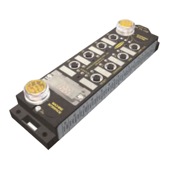
Muting Module MM-TA-12B
Instruction Manual
®
, MICRO-
®
, or other safety
Section Contents
Section 1
Introduction . . . . . . . . . . . . . . . . . . . . . . . . . .Page 3
Section 2
Specifications . . . . . . . . . . . . . . . . . . . . . . .Page 11
Section 3
System Installation . . . . . . . . . . . . . . . . . . . .Page 14
Section 4
Operating Instructions . . . . . . . . . . . . . . . . .Page 39
Section 5
Troubleshooting and Maintenance . . . . . . . .Page 40
Section 6
Checkout Procedures . . . . . . . . . . . . . . . . . .Page 43
Appendix . . . . . . . . . . . . . . . . . . . . . . . . . . .Page 48
Advertisement
Table of Contents

Related Manuals for Banner MM-TA-12B


Summary of Contents for Banner MM-TA-12B
-
Page 1: Table Of Contents
Muting Module MM-TA-12B Instruction Manual Muting Module Features • Compact housing meets IP65 requirements; can be mounted inside or outside a control panel, near the point of safeguarding. • For use with EZ-SCREEN™ Output Signal Switching Device (OSSD) outputs or MINI-SCREEN ®... - Page 2 Auxiliary Output (Aux) ..............page 6 applicable requirements depends upon fac- 1.10 External Device Monitoring (EDM) ..........page 7 tors that are beyond the control of Banner 1.11 Mute Devices and Mute Inputs (M1-M4) ........page 7 Engineering Corp. These factors include the 1.12...
-
Page 3: Introduction
AUX Mute USSI M1, M2, M3, M4 Lamp Figure 1-1. Block diagram of a safeguarding system employing the MM-TA-12B Muting Module and a safety light screen (user- supplied) as a primary safety device Buy: www.ValinOnline.com | Phone 844-385-3099 | Email: CustomerService@valin.com... -
Page 4: Operating Status Leds And Diagnostic Display
MM-TA-12B Muting Module Introduction Instruction Manual Individual features discussed in the following sections are: - Operating Status LEDs and Diagnostic Display - Auto/manual reset MSSI Interface - Lockout conditions (7-pin Mini-style - Control reliability connector, to - Mutable Safety Stop Interface (MSSI) -
Page 5: Lockout Conditions
1/4 second, but not longer than 2 seconds and then re-opening the input. The OSSD outputs will turn ON once the open-closed-open action occurs. In this configuration, the MM-TA-12B Muting Module must be manually reset after power-up, lockouts, and after the cycling of either the MSSI (not muted) or the USSI. -
Page 6: Muteable Safety Stop Interface (Mssi)
+24V dc supply power to the primary safety device that is to be muted. The Module requires redundant input signals from the external primary safeguard which is to be muted. These inputs typically are either two Banner solid-state safety outputs with “handshake capability” (i.e., OSSDs), or two monitored forced-guided relay outputs (i.e., FSDs) from an appropriate safety device. -
Page 7: External Device Monitoring (Edm)
MM-TA-12B Muting Module Introduction Instruction Manual 1.10 External Device Monitoring (EDM) Two inputs are provided (see Figure 1.1) for monitoring the state of external devices, such as MPCEs. These terminals are labeled “EDM1” and “EDM2” at the Machine Interface connection. The Module’s EDM inputs can be configured in three ways: one-channel, two-channel, or no monitoring (see Figure 3-2 for DIP switch settings and Section 3.7.2 for external hookup). -
Page 8: Mute Enable (Me)
MM-TA-12B Muting Module Introduction Instruction Manual Mute Devices WARNING . . . The beginning and end of a mute cycle must be triggered by outputs from either Mute Inputs Must Be pair of muting devices, depending on the application. The mute device pairs both... -
Page 9: Mute Lamp Output (Ml)
MM-TA-12B Muting Module Introduction Instruction Manual 1.13 Mute Lamp Output (ML) WARNING . . . Mute Status Must Be Most applications require that a lamp (or other means) be used to indicate when Readily Observable the primary safety device (e.g., light screen) is muted; the control box provides for this (see WARNING at left). -
Page 10: Override
MM-TA-12B Muting Module Introduction Instruction Manual 1.16 Override WARNING . . . Limit Use of The Override function allows the user to manually force the OSSD outputs ON for Override Function 10 seconds in a situation such as an object becoming “stuck” in the defined area of a safety light screen after the mute ends (e.g., a car body on a transfer line... -
Page 11: Specifications
The MSSI and the USSI can be interfaced with external safety devices that have either hard contact outputs or Banner OSSD safety outputs with Safety Handshake protocol (see Section 3.5.5). When using the MSSI or USSI sourcing outputs, the relay outputs or hard contacts must be capa- ble of switching 15 to 30V dc at 10-50 mA. - Page 12 MM-TA-12B Muting Module Specifications Instruction Manual External Device Two pairs of terminals are provided to monitor the state of external devices controlled by the Monitoring (EDM) OSSD outputs. Each device must be capable of switching 15-30V dc at 10-50 mA.
-
Page 13: Accessories
MQDMC-450RA 50' MQDC-450 MQDC-450RA Double-Ended QD Cordsets (see page 19 for color code and pin-outs) 8-pin Female to 7-pin Male, Mini-Style For connection of 8-pin QD EZ-SCREEN Receivers to MM-TA-12B MSSI connector DES4-508C DES4-515C DES4-525C 4-pin Double-Ended Male/Female, Euro-Style For connection between external devices with a 4-pin Euro-style male connector and the female Euro-style connectors... -
Page 14: System Installation
The user has the sole responsibility to ensure that the Banner MM-TA-12B Muting Module is installed and interfaced to the guarded machine by Qualified Persons in accordance with this manual and applicable safety regulations. A “Qualified Person”... - Page 15 MM-TA-12B Muting Module System Installation Instruction Manual 3.1.1 Muting Application Design WARNING . . . Muting Limitations Following are typical applications where muting is used. See Appendix B for more detailed information. Muting is allowed only during the non-hazardous portion •...
- Page 16 MM-TA-12B Muting Module System Installation Instruction Manual 3.1.4 Pass-Through Hazards WARNING . . . Pass-Through A “pass-through hazard” is associated with applications where personnel may Hazards, Presence- pass through a safeguard (at which point the hazard stops or is removed), and Sensing then may continue into the hazardous area.
-
Page 17: Installing The Module
Instruction Manual 3.2 Installing the Module The MM-TA-12B Muting Module may be installed within a panel or in a NEMA 4/13 IP 65 environment. It must be used with a properly installed and applied safeguard (e.g., safety light screen, interlocked barrier guard). The user must comply with all instructions contained within product manuals and relevant regulations. -
Page 18: Muting Module Configuration
Instruction Manual 3.3 Muting Module Configuration The MM-TA-12B Muting Module should be configured before initial checkout and use. Two banks of DIP switches are located under the access cover for the con- figuration port. To access the DIP switches, unscrew the two captive, round-head slot screws on either side of cover and carefully swing the cover open. - Page 19 (and may be required by code) to iso- Brown +24V dc late wires from high-voltage wires. White OVER Input B *Color code corresponds to Banner accessory QD cordsets list- Blue 0V dc ed in Section 2.1. Black OVER Input A...
-
Page 20: Installing Input Devices
Spare keys in the possession of others, or additional personnel enter- ing the safeguarded area unnoticed may create a hazardous situation. Reset Routine The MM-TA-12B Muting Module requires a manual reset to clear a latch condition and resume operation following a stop command. To perform a manual reset, Black close the normally open reset switch and hold it there for at least 1/4 second, but not longer than 2 seconds, and then re-open the switch. - Page 21 The user must ensure that false “proxing” (activation due to shiny or reflective switches (at M1-M2 or M3-M4) surfaces) is not possible. Banner “LP” sensors with linear polarization can greatly must be properly adjusted or posi- reduce or eliminate this effect.
- Page 22 MM-TA-12B Muting Module System Installation Instruction Manual 3.5.2.3 Muting Device Hookup The Module provides supply voltage, if required, and input connections for the muting devices. One or two pairs of muting devices (typically sensors or switches) must be used; these pairs are designated M1-M2 and M3-M4. The M1 and M3 inputs are PNP (sourcing).
- Page 23 This interface consists of two input channels (A & B), which are compati- WARNING . . . ble with Banner Engineering safety devices that have solid-state OSSD outputs Limit Use of (with “handshake” verification), such as the EZ-SCREEN systems. USSI is also...
- Page 24 (See Figure 3-10.) If OSSDs are to be used without this handshake capability (i.e., non-Banner Safety devices), interposing safety relays or interfacing modules must be used to provide hard contacts and be wired as shown in Figure 3-11.
- Page 25 MM-TA-12B Muting Module System Installation Instruction Manual 3.5.5.1 USSI Emergency Stop Switch Hookup WARNING . . . Emergency Stop As shown in Figure 3-12, the E-stop switch must provide two contacts which are Switch Wiring closed when the switch is armed. Once activated, the E-stop switch must open all...
- Page 26 The safety interlocking switches and actuators used with the MM-TA-12B Muting Module must be designed and installed so that they cannot be easily defeated.
- Page 27 (see the Banner Safety Catalog for exam- ples). In addition, the switches must be mounted in a “positive mode,” to move/disengage the actuator from its home position and open the normally closed contact, when the guard opens.
- Page 28 MM-TA-12B Muting Module System Installation Instruction Manual Monitoring Series-Connected Safety Interlocking Switches When monitoring two individually mounted safety switches (as shown in Figure 3-13), a faulty switch will be detected if it fails to switch as the guard opens. In this case, the Module will de-energize its output relays and disable its reset func- tion until the input requirements are met (i.e., the faulty switch is replaced).
- Page 29 MM-TA-12B Muting Module System Installation Instruction Manual 3.5.5.3 USSI Supplemental Safety System Hookup A variety of safety systems can be interfaced with the MSSI and the USSI. Each safety application has a unique set of application requirements; the user is responsible to ensure proper installation, and use, and that all relevant standards and regulations are complied with.
-
Page 30: Machine Interface Connection - Initial Hookup And Checkout
System or on the machinery being guarded by the System. (See Section 6.1 for a schedule of required checkouts.) For the initial checkout, the MM-TA-12B Muting Module and associated safety sys- tems must be checked without power being available to the guarded machine. Final interface connections to the guarded machine cannot take place until these sys- tems have been checked out. - Page 31 12B Muting Module without a proper earth ground connection at pin 7 of the Machine Interface connector, or at the earth ground screw on the housing. 2) Leaving power to the guarded machine OFF, power up the MM-TA-12B and the safety systems connected to the MSSI and the USSI inputs.
-
Page 32: Permanent Hookup
MM-TA-12B Muting Module System Installation Instruction Manual 9) Generate a stop command from the safeguarding device connected to the MSSI (e.g., interrupt the defined area of a safety light screen). Verify that MSSI Channel A and B indicators go OFF, but the Green status indicator remains ON. - Page 33 OFF state. See Figure 3-17. bodily injury or death. Refer to the output specifications (Section 2) and Warnings at left before making OSSD connections and interfacing the MM-TA-12B Muting Module to the machine. Buy: www.ValinOnline.com | Phone 844-385-3099 | Email: CustomerService@valin.com...
- Page 34 MM-TA-12B Muting Module System Installation Instruction Manual 3.7.4 FSD Interfacing Connections Final switching devices (FSDs) can take many forms, though the most common are captive contact, forced-guided relays or Interfacing Modules. The mechanical linkage between the contacts allow the device to be monitored by the external device monitoring circuit for certain failures.
-
Page 35: Commissioning Checkout
3.8 Commissioning Checkout After power is connected to the MM-TA-12B Muting Module, the EDM has been properly configured, and the OSSD outputs have be connected to the machine to be guarded, the operation of the MM-TA-12B Muting Module with the guarded machine must be verified before the combined System may be put into service. - Page 36 The proper wiring is not exceeded and that the of the MM-TA-12B Muting Module to any particular machine is maximum specified OSSD OFF- solely the responsibility of the installer and end user.
- Page 37 CAUTION . . . Shock Hazard Always disconnect all power from the MM-TA-12B Muting Module and the guarded machine before making any connections or replacing any component. Use extreme caution to avoid electrical shock at all times. Serious bodily injury or death could result.
- Page 38 CAUTION . . . Shock Hazard Always disconnect all power from the MM-TA-12B Muting Module and the guarded machine before making any connections or replacing any component. Use extreme caution to avoid electrical shock at all times. Serious bodily injury or death could result.
-
Page 39: Operating Instructions
Section 6. lems relating to the subject matter and work. If the MM-TA-12B Muting Module, 4.2 Periodic Checkout Requirements safety systems, and the guarded machine do not perform exactly as... -
Page 40: Troubleshooting And Maintenance
MM-TA-12B Muting Module Operating Instructions Instruction Manual 5. Troubleshooting and Maintenance 5.1 Troubleshooting Lockout Conditions A lockout condition causes the OSSD output to turn OFF, sending a stop signal to the guarded machine. A lockout condition is indicated by the Red status indicator flashing and an error code appearing in the Diagnostic Display. - Page 41 MM-TA-12B Muting Module Troubleshooting and Maintenance Instruction Manual Status / Condition / Error Type / Status / Condition / Error Type / Error Code Action Error Code Action — System OK EDM 2 Error (Solid) - Check wiring - Check operation of Device(s) under control —...
-
Page 42: Repairs
Module must not be operating at lowing: any time during this procedure. 1) Contact the Banner applications engineering department at the numbers or You may be working close to a address listed on the front cover. They will attempt to troubleshoot the sys- hazardous area of your machinery while servicing the Module. -
Page 43: Checkout Procedures
Commissioning Checkout: Should be performed after installation or whenever changes are made to the system (either a new configuration of the MM-TA-12B WARNING . . . System or changes to the machine). The procedure must be performed by a Qualified Person. - Page 44 USSI and the MSSI in a non-muted condition. Verify that it is not possible for the guarded machine to be put into motion while either stop commands are present. In order, reset the safeguard and then the MM-TA-12B Module (in Manual Reset).
- Page 45 Muting Checkout 15) Verify that the MM-TA-12B Module has been reset and the Green status indi- cator is ON. If the Yellow status indicator is flashing (indicating the MM-TA-12B system is waiting for a reset of a latched condition), perform a manual reset.
-
Page 46: Daily Checkout
. 8) Check carefully for external signs of damage or changes to the MM-TA-12B system, the interfaced safeguards, the guarded machine, and their electrical wiring. -
Page 47: Semi-Annual Checkout
3) Inspect the guarded machine to verify that no other mechanical or structural problems could prevent the machine from stopping or assuming an other- wise safe condition when signalled to do so by the MM-TA-12B system. 4) Examine and inspect the machine controls and connections to the MM-TA- 12B system to verify that no modifications have been made which adversely affect the System. -
Page 48: Appendix
MM-TA-12B Muting Module Appendix A Instruction Manual Appendix A. Mute Timing Sequences Muting Sequence with Two Muting Devices (For example, “X”-pattern Entry/Exit System, see Figure B-1) DIP Switch Configuration*: Manual Reset ... .SW1 = OFF Power Monitored Muting Lamp . -
Page 49: Appendix B, Typical Muting Applications
MM-TA-12B Muting Module Appendix B Instruction Manual Appendix B. Typical Muting Applications Entry/Exit Applications WARNING . . . The muting devices must be placed to ensure that the points that trigger the mute’s start and end are very close to the safety light screen’s sensing field. This •... - Page 50 MM-TA-12B Muting Module Appendix B Instruction Manual A ≥ (speed of line ft/sec) x 0.1 sec. Hard Guarding B ≈ 3" (suggested position must hinder personnel following muted object) C ≤ Length of carrier basket – Trapping hazards must be avoided and Carrier clearance requirements complied with.
- Page 51 MM-TA-12B Muting Module Appendix B Instruction Manual Home or Station Applications WARNING . . . The muting devices must be placed to ensure that the safety light screen is User is Responsible muted only when the hazard does not exist or is in another area so that person- for Safe Application nel are not exposed.
- Page 52 MM-TA-12B Muting Module Appendix B Instruction Manual Robot Load/Unload Station Application This “station” muting application uses two independent safety light screen cir- cuits, each with its own muting circuit and muting devices (e.g. polarized-retrore- flective photoelectrics). The application also includes run bars with two-hand control, auxiliary controls, and E-Stop.
- Page 53 MM-TA-12B Muting Module Appendix B Instruction Manual Turret Table Application A “Turret Table” application is similar to the Robot Load/Unload Station muting application, except that any movement of the table ends the mute. To accomplish this, small retroreflective targets (or tape) are positioned so that they will initiate the mute (the sensors must be set to “Light Operate”) only after the table has fin-...
- Page 54 MM-TA-12B Muting Module Appendix B Instruction Manual Power Press Applications WARNING . . . Muting is allowed on power presses only during the non-hazardous portion of the Proper Installation cycle (e.g. the upstroke), per OSHA1910.217, ANSI B11.1, B11.2, and B11.3. The...
-
Page 55: Appendix C, Application Safety Standards
MM-TA-12B Muting Module Appendix C Instruction Manual SOURCES U.S. Application Standards ANSI B11 Documents American National Standards ANSI B11.1 ANSI B11.14 Mechanical Power Presses Coil Slitting Machines/ Institute Systems ANSI B11.2 Hydraulic Power Presses 11 West 42nd Street ANSI B11.15 Pipe, Tube, and Shape ANSI B11.3...
Need help?
Do you have a question about the MM-TA-12B and is the answer not in the manual?
Questions and answers