Table of Contents
Advertisement
Quick Links
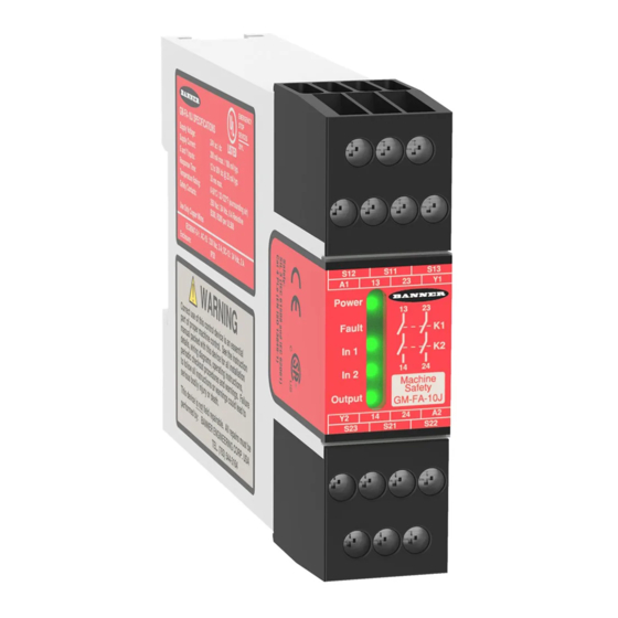
GM-FA-10J Gate Monitoring Safety Module
24V ac/dc operation, 1- or 2-Channel Input
Original Instructions
Overview
The GM-FA-10J Gate Monitor Safety Module (the "Safety Module") is used to verify the proper operation of coded magnetic safety
switches and positive-opening safety switches by monitoring a normally open (N.O.) and a normally closed (N.C.) contact from each
switch. It can also be used to monitor and verify the correct state of two redundant current-sourcing PNP signals. (One PNP source must
be Normally OFF and the other Normally Conducting for each input channel.) In a typical application, two safety switches (individually
mounted) indicate the open or closed status of a gate, moveable guard, or barrier (all called "guards" throughout this document).
Two functions of the Safety Module are:
1. To monitor the contacts and wiring of safety switches for certain failures and to prevent the machine from restarting if the switch or
the Module fails, and
2. To provide a reset routine after closing the guard and returning the inputs to their "closed" condition. This reset function may be
required by machine safety standards.
The Safety Module monitors each switch for complementary switching; each channel must have one open (OFF) input and one closed
(conducting) input at all times. These inputs must always be in opposite states and must switch state within 1 second of each other.
Channel 1 has a "guard closed" condition when S11/S13 is closed and S11/S12 is open. Similarly, Channel 2 has a "guard closed" condi-
tion when S21/S23 is closed and S21/S22 is open (see
Figure 3. Wiring to two positive-opening safety interlock switches
to a short circuit between the channels and a short circuit to other sources of power. The Safety Module will open the safety outputs
within 35 milliseconds of the switching of either channel when the guard opens.
When the guard closes, debounce logic in the Safety Module's inputs increases the reliability and repeatability of successfully resetting
the Safety Module and reduces the necessity of re-cycling the guard. This feature can result in increased efficiency of the machine, even
if the guard is misaligned or vibration is present.
Important: Read This First!
The user is responsible for satisfying all local, state, and national laws, rules, codes, and regulations relating to the use of this
product and its application. Banner Engineering Corp. has made every effort to provide complete application, installation, operation, and
maintenance instructions. Please direct any questions regarding the use or installation of this product to the factory applications depart-
ment at the telephone numbers or address found at Banner website.
The user is responsible for making sure that all machine operators, maintenance personnel, electricians, and supervisors are thorough-
ly familiar with and understand all instructions regarding the installation, maintenance, and use of this product, and with the machinery it
controls. The user and any personnel involved with the installation and use of this product must be thoroughly familiar with all applicable
standards, some of which are listed within the specifications. Banner Engineering Corp. makes no claim regarding a specific recommen-
dation of any organization, the accuracy or effectiveness of any information provided, or the appropriateness of the provided information
for a specific application.
Phone: 800.894.0412 - Fax: 888.723.4773 - Web: www.clrwtr.com - Email: info@clrwtr.com
• Monitors one or two safety switches for a contact failure or wiring fault
• Two output switching channels for connection to control-reliable power in-
terrupt circuits
• Auto reset or monitored manual reset
• Design complies with standards UL991, ISO 14119, and ISO 13849-1
(EN954-1) (Safety Category 2, 3 or 4)
• For use in functional stop category 0 applications per NFPA 79 and IEC
60204-1
• 6 amp safety output contacts
• Plug-in terminal blocks
• If terminal blocks are swapped, Module remains functional with no loss of
safety function
Figure 2. Wiring to two 4-wire coded magnetic safety switches
on page 7). The Safety Module also will detect and properly respond
on page 7 and
Advertisement
Table of Contents

Subscribe to Our Youtube Channel
Related Manuals for Banner GM-FA-10J


Summary of Contents for Banner GM-FA-10J
- Page 1 Overview The GM-FA-10J Gate Monitor Safety Module (the “Safety Module”) is used to verify the proper operation of coded magnetic safety switches and positive-opening safety switches by monitoring a normally open (N.O.) and a normally closed (N.C.) contact from each switch.
- Page 2 GM-FA-10J Gate Monitoring Safety Module Applicable U.S. Standards ANSI B11 Standards for Machine Tools Safety Contact: Safety Director, AMT – The Association for Manufacturing Technology, 7901 Westpark Drive, McLean, VA 22102, Tel.: 703-893-2900 ANSI NFPA 79 Electrical Standard for Industrial Machinery Contact: National Fire Protection Association, 1 Batterymarch Park, P.O.
-
Page 3: Table Of Contents
The EDM circuit consists of a normally closed, force-guided contact from each de- vice being controlled by the Safety Module, all wired in series with the Reset button Figure 1. GM-FA-10J Features and Terminal Lo- (if used) and terminated at terminals Y1 and Y2. See Figure 6. - Page 4 (see the Banner Catalog for examples). In addition, the switches must be mounted in a “positive mode,” to move/disengage the actuator from its home position and open the normally closed contact, when the guard opens.
-
Page 5: Electrical Installation
GM-FA-10J Gate Monitoring Safety Module Electrical Installation Each Safety Module is powered by 24V ac/dc (at less than 150 mA). The Safety Module, in turn, supplies power to each switch. It is not possible to give exact wiring instructions for a Safety Module that interfaces to a multitude of machine control configurations. The following guidelines are general in nature. - Page 6 GM-FA-10J Gate Monitoring Safety Module This check must be performed and all faults must be cleared, at a minimum, during periodic checkouts. If the application can not exclude these types of failures and such a failure could result in serious injury or death, then the series connection of safety switches must not be used.
- Page 7 Figure 2. Wiring to two 4-wire coded magnetic safety switches +24V dc N.O. +24V dc N.C. NOTE: If PNP current-sourcing signals are used, the GM-FA-10J and the current-sourcing devices must be powered from the same DC supply and Common (Com). +24V dc N.O.
- Page 8 Configured for one-channel monitoring of multiple guards with sin- Guard #1 Guard #2 Guard #n gle switches at each guard (see Warning). Up to 10 Banner mag- SI-MAG..MM SI-MAG..MM SI-MAG..MM netic switches may be connected to each channel in this series/ SI-MAG..SM...
-
Page 9: S12 S11 S13
GM-FA-10J Gate Monitoring Safety Module WARNING: Interfacing MPCEs. NEVER wire an intermediate device(s) (e.g., PLC, PES, PC), between the Safety Module outputs and the machine primary control element (MPCE) it switches, in such a manner that in the event of a failure there is the loss of the safety stop command, OR in such a manner that the safety function can be suspended, overridden, or dereated, unless accomplished with the same or greater degree of safety. -
Page 10: S21 S11 S13
GM-FA-10J Gate Monitoring Safety Module • A resistance or similar damping device capable of dissipating the energy of surges When switching inductive ac loads, it is good practice to protect the Safety Module outputs by installing appropriately-sized arc suppres- sors. However, if arc suppressors are used, they must be installed across the load being switched (e. g., across the coils of external safety relays), and never across the Safety Module’s output contacts (see WARNING, Arc Suppressors). -
Page 11: On Page
GM-FA-10J Gate Monitoring Safety Module Reset switch, located outside the area of dangerous motion, and positioned so that the switch operator can see all areas of dangerous motion during the reset procedure. 1-Channel or 2-Channel Input The Safety Module may be configured for 1-channel (“single channel”) or 2-channel (“dual channel”) operation by setting DIP switches S1.1 and S2.1 in Banks A and B. - Page 12 If all of these checks cannot be verified, do not attempt to use the safety system that includes the Banner device and the guarded machine until the defect or problem has been corrected (see Trouble- shooting). Attempts to use the guarded machine under such conditions could result in serious bod- ily injury or death.
-
Page 13: Specifications
GM-FA-10J Gate Monitoring Safety Module Specifications Power General Supply Voltage and Current Pollution Degree 24V dc ±15% @ 150 mA (SELV-rated supply accord- ing to EN IEC 60950, NEC Class 2) Status Indicators 24V ac ±15% @ 150 mA, 50-60 Hz +/- 5% (NEC Class... - Page 14 GM-FA-10J Gate Monitoring Safety Module Inputs Each switch or sensor must have a normally closed 1-Channel operation: infinite contact and a normally open contact capable of switch- ing 20 to 50 mA @ 15 to 30V dc. Reset switch: 20 mA @ 12V dc, hard contact only Max.
- Page 15 GM-FA-10J Gate Monitoring Safety Module Switching Distance Magnet/Sensor Pair Magnet Sensor* Coded Magnet Sensor Cable Min. ON Max. OFF SI-MAG1MM 3 mm (0.12 in- 14 mm (0.55 ches) inches) SI-MAG1MM90†† SI-MAG1SM SI-MAG1SMCO† 8 mm (0.31 in- 16 mm (0.63 SI-MAG1MMHF...
- Page 16 GM-FA-10J Gate Monitoring Safety Module Magnetic Switch Dimensions 25 mm (0.98") 10.7 mm 25 mm (0.42") 6.5 mm (0.98") (0.26") 7.2 mm 13 mm 10.7 mm (0.28") (0.51") (0.42") 4.5 mm 6.5 mm 2.5 mm 3.0 mm (0.18") (3) (0.26") 7.2 mm...
- Page 17 GM-FA-10J Gate Monitoring Safety Module Direction of Approach for SI-MAG1xx Sensor/Magnet Pairs Magnet Sensing face Sensor Coded Magnet Direction of Movement Direction of Movement Normal Direction of Approach: movement is perpendicular to the Incorrect Direction of Approach: Label to label approach of sensor...
- Page 18 GM-FA-10J Gate Monitoring Safety Module Direction of Approach for SI-MAG2xx Sensor/Magnet Pairs Coded Magnet Direction of Movement Magnet Sensor Direction of Movement Normal Direction of Approach: movement is perpendicular to the Incorrect Direction of Approach: Label to label approach of sensor...
-
Page 19: Troubleshooting
Do not attempt any repairs to the Module. It contains no field-replaceable components. Return it to the factory for warranty repair or replacement by contacting Banner Factory Application Engineering. They will attempt to troubleshoot the system from your description of the problem. If they conclude a component is defective, they will issue a return merchandise authorization (RMA) number for your paperwork and give you the proper shipping address. - Page 20 GM-FA-10J Gate Monitoring Safety Module Condition Meaning Input 1 Guard 1 is closed and the inputs of Channel 1 are satisfied. (green) Guard 1 is open or the inputs of Channel 1 are not satisfied. Flashing (along with the Fault Clearing Faults on page 20 for probable cause.
- Page 21 Banner Engineering Corp. warrants its products to be free from defects in material and workmanship for one year following the date of shipment. Banner Engineering Corp. will repair or replace, free of charge, any product of its manufacture which, at the time it is returned to the factory, is found to have been defective during the warranty period.
- Page 22 GM-FA-10J Gate Monitoring Safety Module This Warranty is exclusive and limited to repair or, at the discretion of Banner Engineering Corp., replacement. IN NO EVENT SHALL BANNER ENGINEERING CORP. BE LIABLE TO BUYER OR ANY OTHER PERSON OR ENTITY FOR ANY EXTRA COSTS, EXPEN-...
Need help?
Do you have a question about the GM-FA-10J and is the answer not in the manual?
Questions and answers