Table of Contents
Advertisement
Quick Links
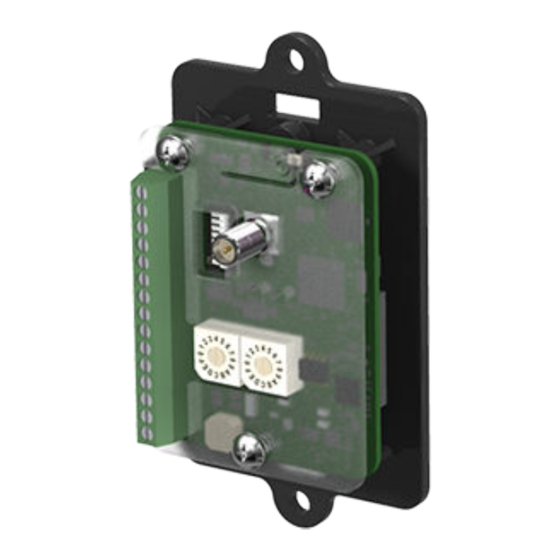
SureCross MultiHop Data Radio Module
Configurable FlexPower MultiHop radio module with discrete and analog I/O
For additional information, the most recent version of all documentation, and a complete list of accessories, refer to Banner Engineering's
website, www.bannerengineering.com/surecross.
Models
Power
DX80DR9M-HB1
10 to 30V dc or 3.6
to 5.5V dc low pow-
er option
DX80DR2M-HB1
WARNING: Not To Be Used for Personnel Protection
Never use this device as a sensing device for personnel protection. Doing so could lead to serious
injury or death. This device does NOT include the self-checking redundant circuitry necessary to allow its
use in personnel safety applications. A sensor failure or malfunction can cause either an energized or de-
energized sensor output condition.
CAUTION: Electrostatic Discharge (ESD)
ESD Sensitive Device. Use proper handing procedures to prevent ESD damage to these devices. The
module does not contain any specific ESD protection beyond the structures contained in its integrated cir-
cuits. Proper handling procedures should include leaving devices in their anti-static packaging until ready
for use; wearing anit-static wrist straps; and assembling units on a grounded, static-dissipative surface.
CAUTION: Never Operate 1 Watt Radios Without Antennas
To avoid damaging the radio circuitry, never power up SureCross Performance or SureCross MultiHop (1
Watt) radios without an antenna.
P/N 154365 Rev. C
SureCross® MultiHop embeddable board devices were specifically designed for the
needs of industrial users to provide connectivity where traditional wired connections are
not possible or cost prohibitive.
• Wireless industrial module with two sinking discrete inputs, two NMOS discrete out-
puts, two 0 to 20 mA analog inputs, and two switch power outputs
• Selectable transmit power levels of 250 mW or 1 Watt and license-free operation up to
4 watt EIRP, with a high-gain antenna, in the U.S. and Canada for 900 MHz
• FlexPower® power options allows for +10 to 30V dc, solar, and battery power sources
for low power applications.
• Self-healing, auto-routing RF network with multiple hops extends the network's range
• Serial and I/O communication on a Modbus platform
• Message routing improves link performance
• DIP switches select operational modes: master, repeater, or slave
• Switched power outputs provide 5 to 24V dc power to external sensors
• FHSS radios operate and synchronize automatically; selectable network IDs reduce
interference from collocated networks
Frequency
Transmit Power
900 MHz ISM
250 mW or 1 Watt (DIP
Band
switch selectable)
2.4 GHz ISM
63 mW (100 mW EIRP)
Band
2/27/2013
I/O
Inputs: Two sinking discrete, two 0 to 20 mA
analog
Outputs: Two NMOS discrete
Switch Power Outputs: Two
0 154365
0
Advertisement
Table of Contents

Related Manuals for Banner DX80DR9M-HB1


Summary of Contents for Banner DX80DR9M-HB1
- Page 1 • Switched power outputs provide 5 to 24V dc power to external sensors • FHSS radios operate and synchronize automatically; selectable network IDs reduce interference from collocated networks For additional information, the most recent version of all documentation, and a complete list of accessories, refer to Banner Engineering's website, www.bannerengineering.com/surecross. Models...
- Page 2 (wired) bus. MultiHop Configuration Tool Use Banner’s MultiHop Configuration Tool software to view your MultiHop radio network and configure the radio and its I/O. www.bannerengineering.com - tel: 763-544-3164 P/N 154365 Rev. C...
-
Page 3: Configuring The Dip Switches
USB to RS-485 (for RS-485 radios) or a USB to RS-232 (for RS-232 radios) converter cable. For RS-485 models, Banner recommends using cable model BWA-UCT-900, an RS-485 to USB adapter cable with a wall plug that can power your 1 Watt MultiHop radio while you are configuring it. - Page 4 SureCross MultiHop Data Radio Module Switches Device Settings Parity: Even Parity: Odd Disable serial (low power mode) and enable the receiver slots select for switches 1-2 900 MHz: 1.00 Watt (30 dBm) transmit power ** OFF* 2.4 GHz models: 40 ms frame 900 MHz: 0.25 Watts (24 dBm) transmit power ** 2.4 GHz models: 20 ms frame Application mode: Modbus...
-
Page 5: Wiring Diagrams
SureCross MultiHop Data Radio Module Wiring Diagrams Description Diagram Label Analog IN 1 (0 to 20 mA) 45.72 [1.8”] Analog IN 2 (0 to 20 mA) 30.48 [1.2”] Discrete IN 3 (NPN) Discrete IN 4 (NPN) Binding button Ground Switch Power 1 (see Switch Power out- put register definition) Antenna connection 53.34... - Page 6 SureCross MultiHop Data Radio Module only from the master to which it is bound. The binding code defines the network, and all radios within a network must use the same binding code. After binding your MultiHop radios to the master radio, make note of the binding code displayed under the *DVCFG menu, - BIND submenu on the LCD.
-
Page 7: Modbus Register Table
SureCross MultiHop Data Radio Module Two Button/LED Models Single Button/LED Models Process Response LED 1 LED 2 Steps The slave/repeater searches for a parent device. Flashes red Flashes red (1 per 3 sec) A parent device is detected. The slave/repeater searches Solid red Solid red for other parent radios within range. -
Page 8: Factory Default Configuration
2, counter 1, etc. Not all inputs or outputs may be available for all models. To determine which specific I/O is available on your model, refer to the Modbus Input/Output Register Maps listed in the device's data sheet. For more information about registers, refer to the MultiHop Product Manual, Banner part number 151317. Factory Default Configuration... -
Page 9: Switch Power
SureCross MultiHop Data Radio Module Switch Power I/O Group Continuous Voltage Default Output Voltage Hold Last Voltage Ena- Switch Power (all) Specifications Radio General Radio Range Power* 900 MHz: Up to 9.6 kilometers (6 miles) * Requirements: +10 to 30V dc (For European applica- tions: +10 to 24V dc, ±... - Page 10 The manufacturer does not take responsibility for the violation of any warning listed in this document. Make no modifications to this product. Any modifications to this product not expressly approved by Banner Engineering could void the user’s authority to operate the product.
-
Page 11: Antenna Installation
Banner Engineering Corp. warrants its products to be free from defects in material and workmanship for one year following the date of shipment. Banner Engineering Corp. will repair or replace, free of charge, any product of its manufacture which, at the time it is returned to the factory, is found to have been defective during the warranty period.
Need help?
Do you have a question about the DX80DR9M-HB1 and is the answer not in the manual?
Questions and answers