Banner MMD-TA-11B Instruction Manual

Banner MMD-TA-11B Instruction Manual

Muting module

Advertisement

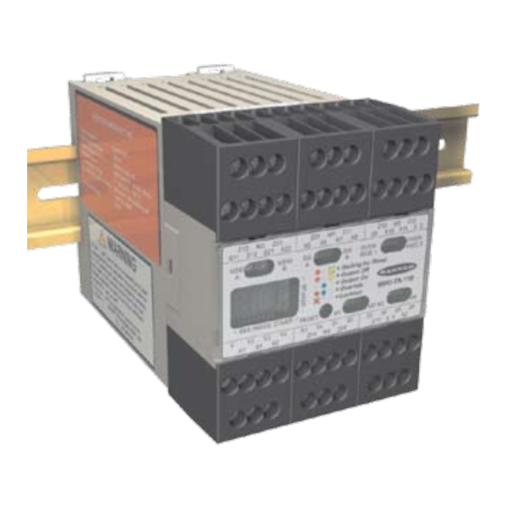
Models MMD-TA-11B and MMD-TA-12B
Features
• Compact, 67.5 mm DIN-mounted housing with
plug-in terminal blocks.
®
• For use with EZ-SCREEN
Output Signal Switching
Device (OSSD) outputs or MINI-SCREEN
®
SCREEN
, MACHINE-GUARD
devices with hard relay contact safety output(s) or
+24V dc (PNP) outputs.
• Monitors two or four inputs to automatically suspend
the safety function of a safeguarding device.
• Can be used as a dual controller when muting
function is not used.
• Safety (protective) Stop Interface (SSI) for connection
of supplemental safeguarding devices, E-stops, or
other devices.
• Category 2, 3, or 4 hookup per ISO 13849-1/-2.
• Selectable external device monitoring (EDM).
• Selectable Automatic or Monitored Manual Reset
provides flexibility for point-of-operation, area, or
perimeter guarding.
• Two N.O. safety contacts (model MMD-TA-11B) or
diverse-redundant solid-state safety outputs (model
MMD-TA-12B).
• Status LEDs and two-digit Diagnostic Display indicate
module status.
• Easy configuration for:
Auto/manual reset
One-/two-channel EDM
One-/two-direction muting
Selectable mute enable
Monitored/non-monitored mute lamp
Selectable backdoor timer
Selectable mute on power-up
Phone: 800.894.0412 - Fax: 888.723.4773 - Web: www.clrwtr.com - Email: info@clrwtr.com
Muting Module
Instruction Manual
®
, MICRO-
®
, or other safety
Section 1
Section 2
Section 3
Section 4
Section 5
Section 6
Section Contents
Introduction . . . . . . . . . . . . . . . . . . . . . . . . . . . . . . . . . . . . . Page 1
Components and Specifications . . . . . . . . . . . . . . . . . . . . . Page 8
System Installation . . . . . . . . . . . . . . . . . . . . . . . . . . . . . . . Page 12
Operating Instructions . . . . . . . . . . . . . . . . . . . . . . . . . . . . . Page 39
Troubleshooting and Maintenance . . . . . . . . . . . . . . . . . . . Page 40
Checkout Procedures . . . . . . . . . . . . . . . . . . . . . . . . . . . . . Page 42
Appendix . . . . . . . . . . . . . . . . . . . . . . . . . . . . . . . . . . . . . . . Page 45

Advertisement

Table of Contents
loading
Need help?

Need help?

Do you have a question about the MMD-TA-11B and is the answer not in the manual?

Questions and answers

Summary of Contents for Banner MMD-TA-11B

  • Page 1: Table Of Contents

    • Selectable external device monitoring (EDM). • Selectable Automatic or Monitored Manual Reset provides flexibility for point-of-operation, area, or perimeter guarding. • Two N.O. safety contacts (model MMD-TA-11B) or diverse-redundant solid-state safety outputs (model Section Contents MMD-TA-12B). • Status LEDs and two-digit Diagnostic Display indicate Section 1 Introduction .
  • Page 2 Table of Contents MMD-TA-11B / MMD-TA-12B Muting Module Instruction Manual Important ... Table of Contents read this before proceeding! 1. Overview ....................... page 1 Introduction ..................... page 1 In the United States, the functions that the Operating Status LEDs and Diagnostic Display ........page 2 Banner MMD-TA-11B and MMD-TA-12B Automatic or Monitored Manual Reset Select ........
  • Page 3: Introduction

    Instruction Manual 1. Overview 1.1 Introduction The Banner MMD-TA-11B / MMD-TA-12B Muting Module (the The muting function allows material to be manually or Module) is an accessory component of a safeguarding system, automatically fed into or removed from a machine process, which may incorporate such primary safeguards as safety light without tripping the primary safeguard.
  • Page 4: Operating Status Leds And Diagnostic Display

    Overview MMD-TA-11B / MMD-TA-12B Muting Module Instruction Manual Individual features discussed in the following sections are: 1.2 Operating Status LEDs and Diagnostic Display - Operating Status LEDs and Diagnostic Display - Auto/manual reset The Module has three Operating Status LEDs (one each red,...
  • Page 5: Automatic Or Monitored Manual Reset Select

    MMD-TA-11B / MMD-TA-12B Muting Module Overview Instruction Manual 1.4 Lockout Conditions 1.3 Automatic or Monitored Manual Reset Select A lockout condition of the Module will cause both OSSD outputs The selectable Automatic or Monitored Manual Reset (X1−X2) to go OFF. A lockout condition is indicated by a flashing Red...
  • Page 6: Muteable Safety Stop Interface (Mssi)

    The Module requires redundant input signals from the external Section 3.5.4 for more information. primary safeguard which is to be muted. These inputs typically are either two Banner solid-state safety outputs or two monitored forced-guided relay outputs from an appropriate safety device. 1.10 External Device Monitoring (EDM) See Section 2, Specifications, and Section 3.5.6 for complete...
  • Page 7: Mute Inputs (M1-M4) And Mute Devices

    MMD-TA-11B / MMD-TA-12B Muting Module Overview Instruction Manual Mute Devices 1.11 Mute Inputs (M1−M4) and Mute Devices The beginning and end of a mute cycle must be triggered by outputs from either pair of muting devices, depending on the The Muting Function application.
  • Page 8: Mute Lamp Output (Ml)

    Overview MMD-TA-11B / MMD-TA-12B Muting Module Instruction Manual If the Backdoor Timer expires, a #50 error code will be displayed 1.13 Mute Lamp Output (ML) until all mute device inputs are open and the MSSI is active (closed). Some applications require that a lamp (or other means) be used The Backdoor Timer can be disabled (i.e., set for infinite time).
  • Page 9: Override

    MMD-TA-11B / MMD-TA-12B Muting Module Overview Instruction Manual 1.16 Override 1.17 One-Way/Two-Way Muting The Override function (X9−X10, X11−X12) allows the user to One-way (directional) muting allows the safeguard to be muted manually force the OSSD outputs ON for up to 30 seconds in a only if mute devices are actuated in the order M1, M2, (mute situation such as an object becoming “stuck”...
  • Page 10: Components And Specifications

    2. Components and Specifications 2.1 Specifications System Power Requirements Model MMD-TA-11B: +24V dc ±15% @ 300 mA max (SELV/PELV) Model MMD-TA-12B: +24V dc ±15% @ 250 mA max (SELV/PELV) (not including draw of the MSSI power, AUX, ML, M1-M4 and OSSD connections).
  • Page 11 MMD-TA-11B / MMD-TA-12B Muting Module Components and Specifications Instruction Manual 2.1 Specifications, continued Non-Safety Outputs Model MMD-TA-11B: Aux. output 31–32 is a parallel connection of two N.C. contacts from internal relays K1 and K2. Contact: AgNi, 5 µm gold-plated Low Current Rating: Caution: The 5 µm gold-plated contacts allow the switching of low current/low voltage.
  • Page 12 MMD-TA-11B / MMD-TA-12B Muting Module Components and Specifications Instruction Manual 2.1 Specifications, continued Inputs The MSSI and the SSI can be interfaced with external devices that have either hard contact outputs or solid state sourcing outputs. When connecting the MSSI (S11–S12, S21–S22) or SSI (X5–X6, X7–X8) inputs to relay outputs or hard contacts, these contacts must be capable of switching 15–30V dc at 10–50 mA.
  • Page 13: Accessories

    MMD-TA-11B / MMD-TA-12B Muting Module System Installation Instruction Manual 2.1 Specifications, continued Application Notes Mute Timing Sequences: see Appendix A Typical Muting Applications: see Appendix B Application Standards: see inside back cover 2.2 Accessories Solid-State LED-Based Mute Lamp +24V dc, White lens, stack-light style on SSA-ML-W 12"...
  • Page 14: System Installation

    WARNING . . . Read this Section Carefully Before Installing the System The correct application of the MMD-TA-11B and -12B Muting Modules is dependent on the type of machine and the The Banner MMD-TA-11B or -12B Muting safeguards that are to be interfaced with the Module. The...
  • Page 15 MMD-TA-11B / MMD-TA-12B Muting Module System Installation Instruction Manual 3.1.1 Muting Application Design 3.1.2 Use of Corner Mirrors with Optical Safety Systems Following are typical applications where muting is used. See Mirrors are typically used with safety light screens and single-/ Appendix B for more detailed information.
  • Page 16: Installing The Module

    MMD-TA-11B / MMD-TA-12B Muting Module System Installation Instruction Manual 3.1.4 Pass-Through Hazards WARNING . . . Pass-Through Hazards, Presence-Sensing Safeguarding A “pass-through hazard” is associated with applications where Devices, and Muting personnel may pass through a safeguard (at which point the...
  • Page 17: Muting Module Configuration

    MMD-TA-11B / MMD-TA-12B Muting Module System Installation System Installation Instruction Manual 3.3 Muting Module Configuration The Muting Module should be configured before initial checkout and use. Two banks of DIP switches are located under the front cover. To access the DIP switches, use a screwdriver to gently pry the cover loose from the Module housing.
  • Page 18: Connection Terminals/Functions

    Reset In Muting 4 In (NPN) Mute Enable In Potential Reset Out (24V) M4, 24V 0V dc High-Voltage Terminals *contacts only Figure 3-4a. MMD-TA-11B terminal connection locations Terminal Function Terminal Function Terminal Function M3, 0V M1, 24V M2, 0V All terminals are low-voltage...
  • Page 19: Installing Input Devices

    MMD-TA-11B / MMD-TA-12B Muting Module System Installation Instruction Manual Reset Routine To remove a terminal block, insert The Muting Module requires a manual reset to clear a latch a small screwdriver into the slot condition and resume operation following a stop command. To shown, and pry to loosen.
  • Page 20 “proxing” (activation due to shiny General Muting Device Requirements or reflective surfaces) is not possible. Banner “LP” sensors with The muting devices (typically sensors or switches) must, at a linear polarization can greatly reduce or eliminate this effect.
  • Page 21 MMD-TA-11B / MMD-TA-12B Muting Module System Installation Instruction Manual Muting Device Hookup +24V dc The Module provides supply voltage, if required, and input connections for the muting devices. One or two pairs of muting devices (typically sensors or switches) must be used; these pairs MMD-TA-..B...
  • Page 22 = ON, banks A and B). The current draw of the mute lamp must not exceed 360 mA. See Figure 3-10. 3.5.4 Auxiliary Output (AUX) Figure 3-11a. AUX output hookup – MMD-TA-11B Model MMD-TA-11B: The non-safety-related output on this model is a 24V ac/dc, 250 mA normally-closed relay contact.
  • Page 23 This interface consists of two input channels (A R15.06 Industrial Robots, ANSI B11 Machine Tools, OSHA and B), which are compatible with Banner Engineering safety 29CFR1910.217 Mechanical Power Presses, and ISO 13849-1 devices that have solid-state OSSD outputs or other devices with (EN954-1) Safety-Related Parts of a Control System.
  • Page 24 MMD-TA-11B / MMD-TA-12B Muting Module System Installation Instruction Manual Category 3 3.5.6.2 Generic SSI and MSSI Hookups To meet the requirements of a category 3 application, any device connected to the SSI and MSSI inputs must meet certain criteria. To fully understand category requirements, refer to standard For example, a “type 3”...
  • Page 25 MMD-TA-11B / MMD-TA-12B Muting Module System Installation Instruction Manual Category 4 +24V dc To ensure a category 4 application, any device connected to the MMD-TA-..B SSI and MSSI inputs must meet certain criteria. For example, a “type 4” safety light screen (curtain) that meets IEC 61496-1/-2 is MSSI or SSI a device that meets category 4 requirements.
  • Page 26 MMD-TA-11B / MMD-TA-12B Muting Module System Installation Instruction Manual 3.5.6.3 SSI Emergency Stop Switch Device Hookup WARNING . . . Emergency Stop Functions Emergency Stop Push Button Switches Do not connect any device to the MSSI Input As shown in Figures 3-16, 3-17 and 3-18, the E-stop switch must that is used for an emergency stop function.
  • Page 27 MMD-TA-11B / MMD-TA-12B Muting Module System Installation Instruction Manual Category 3 Category 4 A dual-channel hookup switching +24V dc is typically a category The self-monitoring SSI inputs can be interfaced to achieve a 3 application, because a single failure does not result in a loss category 4 application.
  • Page 28 (see the Banner Safety Catalog for examples). maintain each safety system and comply with all relevant laws In addition, the switches must be mounted in a “positive mode,”...
  • Page 29 MMD-TA-11B / MMD-TA-12B Muting Module System Installation Instruction Manual The systems in either scenario do not inherently comply with the safety standard requirements of detecting single faults and preventing the next cycle. In multiple-guard systems using series-connected safety switches, it is important to periodically check the functional integrity of each interlocked guard individually.
  • Page 30 MMD-TA-11B / MMD-TA-12B Muting Module System Installation Instruction Manual Category 3 +24V dc 0V dc A dual-channel hookup switching +24V dc is typically a category MMD-TA-..B 3 application, because a single failure does not result in a loss of safety. Loss of the switching action in one channel is detected...
  • Page 31 MMD-TA-11B / MMD-TA-12B Muting Module System Installation Instruction Manual information. This application is widely used in a variety of 3.5.6.5 SSI Supplemental Safety System Hookup situations, including manufacturing cells, robotic cells, palletizers, and de-stackers. One of the many requirements of this muting...
  • Page 32: Machine Interface - Initial Hookup And Checkout

    4. Verify that the external safety systems are providing a configuring the safety systems connected to its MSSI and the Green/Go signal to the MSSI and SSI inputs (i.e., Banner SSI inputs (per Section 3). OSSD sourcing signal or a closed contact connected to the “Signal”...
  • Page 33: Permanent Hookup To The Guarded Machine

    MMD-TA-11B / MMD-TA-12B Muting Module System Installation Instruction Manual If the Muting function is not used, proceed to Section 3.7. 3.7 Permanent Hookup to the Guarded Machine During the initial checkout procedure of the Muting feature, if possible, verify that the power has been removed or is otherwise...
  • Page 34 MMD-TA-11B / MMD-TA-12B Muting Module System Installation Instruction Manual 3.7.1 Mute Enable Hookup 3.7.2 External Device Monitoring (EDM) Hookup The Module provides a Mute Enable input (“ME,” X13−X14) for The Module provides connection terminals for the External the connection of a potential free contact (see Section 1.12).
  • Page 35 This applies equally to the safety relays of monitoring circuit for certain failures. the model MMD-TA-11B and the solid-state output of the model Dependent on the application, the use of FSDs can facilitate MMD-TA-12B.
  • Page 36: Commissioning Checkout

    MMD-TA-11B / MMD-TA-12B Muting Module System Installation Instruction Manual Dual-Channel Control Methods to exclude the possibility of these failures include, but are not limited to: Dual-channel (or two-channel) control has the ability to electrically extend the safe switching point beyond the FSD •...
  • Page 37 MMD-TA-11B / MMD-TA-12B Muting Module System Installation Instruction Manual WARNING . . . Use of Transient +24V dc 0V dc Suppressors MMD-TA-12B Transient suppressors are recommended. They MUST be installed across the coils of the machine control elements. NEVER install suppressors...
  • Page 38 MMD-TA-11B / MMD-TA-12B Muting Module System Installation Instruction Manual +24V dc 0V dc MMD-TA-12B EDM1 EDM2 OSSD1 OSSD2 IM-T-9A +24V dc MPCE WARNING . . . OSSD Interfacing MPCE Machine Control To ensure proper operation, the Muting Module output parameters and machine...
  • Page 39 MMD-TA-11B / MMD-TA-12B Muting Module System Installation Instruction Manual WARNING . . . 0V dc Use of Transient +24V dc Suppressors MMD-TA-12B Transient suppressors are recommended. They MUST be installed across the coils of the machine control elements. EDM1 NEVER install suppressors...
  • Page 40 MMD-TA-11B / MMD-TA-12B Muting Module System Installation Instruction Manual +24V dc 0V dc +24V dc 0V dc MMD-TA-11B MMD-TA-11B EDM1 EDM1 EDM2 EDM2 Machine MPCE1 Machine MPCE1 Control Control Circuits Circuits MPCE2 MPCE2 Figure 3-27. Generic machine interface hookup, model Figure 3-28.
  • Page 41: Operating Instructions

    MMD-TA-11B / MMD-TA-12B Muting Module Operating Instructions Instruction Manual 4. Operating Instructions 4.1 Security Protocol 4.3 Normal Operation The Module must be mounted inside a lockable enclosure or During normal operation, the Module’s three status indicators cabinet rated IP54 or better, both to protect the Module from (red, green and yellow) are as shown in Figure 4-1.
  • Page 42: Troubleshooting And Maintenance

    (if fault was due to an input failure), or a reset routine must be performed. 1. Contact the Banner applications engineering department at the numbers or address listed on the front cover. They will To perform a reset, close the reset input, hold closed for at least...
  • Page 43 MMD-TA-11B / MMD-TA-12B Muting Module Troubleshooting and Maintenance Instruction Manual Status Condition / Error Type / Status Condition / Error Type / Error Code Action Error Code Action — System OK EDM 2 Error (Solid) - Verify that input 2 is open (single-channel EDM selected) —...
  • Page 44: Checkout Procedures

    Refer all questions to to the Machine the Banner Applications Engineering Department at the address or numbers listed on the front cover of this manual. Checkouts Verify that the guarded area is clear of must be performed as detailed in Section 6.1 below and results...
  • Page 45 MMD-TA-11B / MMD-TA-12B Muting Module Periodic Checkout Procedures Instruction Manual 6. Apply power to the Module. Ensure that power to the Muting Checkout guarded machine is OFF. Verify that the external safety 13. Verify that the Module has been reset and the Green status systems are providing a Green/Go signal to the MSSI and indicator is ON.
  • Page 46: Daily Checkout

    MMD-TA-11B / MMD-TA-12B Muting Module Periodic Checkout Procedures Instruction Manual 7. With the guarded machine at rest, generate a stop 6.3 Daily Checkout command from the safeguarding device(s) and verify that it is not possible for the guarded machine to be put into Perform this checkout procedure at every shift change, power- motion.
  • Page 47: Appendix

    MMD-TA-11B / MMD-TA-12B Muting Module Appendix A Instruction Manual Appendix A. Mute Timing Sequences Muting Sequence with Two Muting Devices Power (For example, “X”-pattern Entry/Exit System, MSSI see Figure B-1) Open Open Open Closed Reset Reset Reset System Reset DIP Switch Configuration*: AUX Outputs MSSI Auto or Manual Reset.
  • Page 48: Appendix B, Typical Muting Applications

    MMD-TA-11B / MMD-TA-12B Muting Module Appendix B Instruction Manual Appendix B. Typical Muting Applications Entry/Exit Applications WARNING . . . The muting devices must be placed to ensure that the points that trigger the mute’s start and end are very close to the safety light screen’s sensing field.
  • Page 49 MMD-TA-11B / MMD-TA-12B Muting Module Appendix B Instruction Manual A ≥ (speed of line ft/sec) x 0.1 sec. B ≈ 3" or position must hinder personnel following muted object Hard Guarding C ≤ Length of carrier basket – Trapping hazards must be avoided and clearance requirements complied with.
  • Page 50 MMD-TA-11B / MMD-TA-12B Muting Module Appendix B Instruction Manual Home or Station Applications The muting devices must be placed to ensure that the safety Light Screen Light Screen Emitter Receiver light screen is muted only when the hazard does not exist or is in another area so that personnel are not exposed.
  • Page 51 MMD-TA-11B / MMD-TA-12B Muting Module Appendix B Instruction Manual While the robot is at station “A”, the light screen at station “B” is Robot Load/Unload Station Application muted (M1B and M2B are active), allowing the operator to load This “station” muting application uses two independent safety or unload without issuing a stop command to the robot.
  • Page 52 MMD-TA-11B / MMD-TA-12B Muting Module Appendix B Instruction Manual When the table begins indexing again, the polarized- Turret Table Application retroreflective photoelectrics immediately “lose sight” of the A “Turret Table” application is similar to the Robot Load/Unload targets and end the mute. Since the rotation of the table is the...
  • Page 53 MMD-TA-11B / MMD-TA-12B Muting Module Appendix B Instruction Manual In muting applications involving an operator, all pass-through Power Press Applications hazards must be eliminated so that the operator is continually Muting is allowed on power presses only during the non- detected when in the defined area.
  • Page 54: Glossary Of Terms

    Brake: a mechanism for stopping or preventing motion.. Lockout condition are permitted; failures which cause an unsafe condition (a failure to danger) are not. Banner safety products Clutch: a mechanism that, when engaged, transmits torque to are extensively FMEA tested.
  • Page 55 When inserted into any part of the defined area, it will place a system into a Trip or Latch condition. Banner ON State: The state in which the output circuit is complete and supplies specified test pieces with each system.
  • Page 56 MMD-TA-11B / MMD-TA-12B Muting Module Glossary of Terms Instruction Manual Test Piece: an opaque object of sufficient size used to block a light beam to test the operation of a safety light screen system. Trip Condition: the response of the safety outputs (e.g.,...
  • Page 57 The list of standards below is included as a convenience for users of this Banner product. Inclusion of these standards does not imply that the product complies specifically with any standard, other than those listed in the Specifications section of this manual.

This manual is also suitable for:

Mmd-ta-12b

Table of Contents