Table of Contents
Advertisement
Quick Links
Models
Model
ES-TN-1H1
0.25 second
ES-TN-1H2
0.5 second
ES-TN-1H3
1 second
ES-TN-1H4
2 seconds
ES-TN-1H7
4 seconds
ES-TN-1H8
6 seconds
ES-TN-1H9
8 seconds
ES-TN-1H10
10 seconds
ES-TN-1H11
15 seconds
ES-TN-1H12
20 seconds
!
WARNING . . .
This Emergency Stop
Safety Module is not
a point-of-operation
guarding device, as defined by OSHA
regulations. It is necessary to install
point-of-operation guarding devices,
such as safety light screens and/or
hard guards, to protect personnel
from hazardous machinery. Failure to
install point-of-operation guards on
hazardous machinery can result in a
dangerous condition which could lead
to serious injury or death.
Printed in USA
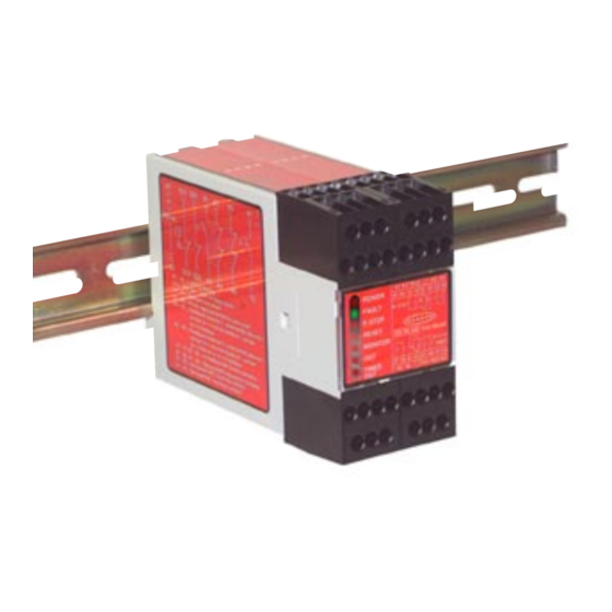
ES-TN-1H.. E-Stop Safety Modules with Fixed Delay
®
Models with fixed delay, ranging from 0.25 second to 20 seconds
Delay
• Selectable Auto-Reset or monitored Manual Reset.
• Auto or manual power-up
• One- or two-channel feedback monitoring
• Monitors one dual-channel or one single-channel normally closed E-stop
switch circuit for a contact failure or wiring fault (Safety Category 2 or 4,
per ISO13849-1 [EN954-1]; see pages 5 and 6).
• 4 amp safety output contacts
• Removable terminal blocks
• Input monitoring circuit has diverse-redundant microprocessors
• Designed for use in functional stop Category 0 and 1 applications
(per ISO/EN 60204-1 and NFPA79)
• Two immediate output switching channels (functional stop Category 0) and
two delayed output switching channels (functional stop Category 1).
• One auxiliary non-safety, normally closed immediate output and one auxiliary
non-safety normally closed delayed output for status monitoring.
Features
12/04
P/N 61061 rev. A
Advertisement
Table of Contents

Related Manuals for Banner ES-TN-1H Series


Summary of Contents for Banner ES-TN-1H Series
- Page 1 ES-TN-1H.. E-Stop Safety Modules with Fixed Delay ® Models with fixed delay, ranging from 0.25 second to 20 seconds Models Model Delay ES-TN-1H1 0.25 second ES-TN-1H2 0.5 second ES-TN-1H3 1 second ES-TN-1H4 2 seconds ES-TN-1H7 4 seconds ES-TN-1H8 6 seconds ES-TN-1H9 8 seconds ES-TN-1H10...
- Page 2 Banner Engineering Corp. has made every effort to provide complete application, installation, operation, and maintenance instructions. In addition, any questions regarding the use or installation of this Banner Emergency Stop Safety Module should be directed to the factory applications department at the telephone numbers or address shown on back cover.
- Page 3 For more information, refer to standards EN954-1, EN418, NFPA 79, EN60204-1 and British Standard 5304:(1988). Banner Engineering Corp. Minneapolis, MN U.S.A. • www.bannerengineering.com • Tel: 763.544.3164 P/N 61061 rev. A...
- Page 4 (Out) and delayed outputs (Timed-Out); see Figure 1. E-Stop Safety Modules ES-TN-1H.. have no user-serviceable parts. See page 16 for information regarding repair service. Figure 1. ES-TN-1H.. status indicators Banner Engineering Corp. Minneapolis, MN U.S.A. • www.bannerengineering.com • Tel: 763.544.3164...
- Page 5 2 seconds of the first one; if not, the unit will go into a lockout condition that results in the outputs opening and requiring a reset after the fault has been corrected. Banner Engineering Corp. Minneapolis, MN U.S.A. •...
-
Page 6: Mechanical Installation
Failure to do so could result in undetected faults and create an unsafe condition which could result in serious injury or death. Banner Engineering Corp. Minneapolis, MN U.S.A. • www.bannerengineering.com • Tel: 763.544.3164 P/N 61061 rev. A... - Page 7 Reset mode) before the time-out occurs will result in a lockout (see page 14 for instructions for clearing lockouts). *** Arc suppressors (see Warning). Figure 3. E-Stop Safety Modules ES-TN-1H.. hookups Banner Engineering Corp. Minneapolis, MN U.S.A. • www.bannerengineering.com • Tel: 763.544.3164...
-
Page 8: External Device Monitoring (Edm)
Reset of the Safety Module is not possible if one switch fails to open, or if a short circuit occurs between the safety switches or to dc common or to +24V. Please contact the Banner Factory Applications Group at the numbers listed on the last S11 S21 page to discuss your intended use. - Page 9 Reset button is pushed and released. If Manual Power-Up and Auto Reset is selected, the E-stop button must be cycled (opened and closed) if it is closed after power up (but simply closed if it is open after power-up). Banner Engineering Corp. Minneapolis, MN U.S.A. •...
- Page 10 X3-X4 and X5-X6 inputs and select 2-channel monitoring. It is the responsibility of the user to ensure that any single failure will not result in a hazardous condition and will prevent a successive machine cycle. Banner Engineering Corp. Minneapolis, MN U.S.A. •...
- Page 11 1 CHANNEL MONITORING AUTO POWER UP MANUAL POWER UP 1 CH. INPUT 2 CH. INPUT Figure 6. Module DIP switches and selectors, set to factory settings Banner Engineering Corp. Minneapolis, MN U.S.A. • www.bannerengineering.com • Tel: 763.544.3164 P/N 61061 rev. A...
- Page 12 Safety Module front cover. Then insert the blade of a small screwdriver into one of the four depressions in the Safety Module front cover and pry them loose; see Figure 7. Banner Engineering Corp. Minneapolis, MN U.S.A. •...
-
Page 13: Periodic Checkout Procedure
OFF – Both internal relays K3 and K4 are de-energized. (Delayed N.O. outputs 37-38 and 47-48 are open. Delayed N.C. output 61-62 is closed.) Flashing (Fault LED ON) – See Fault Indication Table for probable cause. Banner Engineering Corp. Minneapolis, MN U.S.A. •... -
Page 14: Clearing Faults
In Manual Reset mode, the E-Stop button was re-armed (closed) and the Reset button pushed RESET ON or OFF and released with Cancel Delay input closed. MONITOR ON or OFF TIMED-OUT FLASHING Banner Engineering Corp. Minneapolis, MN U.S.A. • www.bannerengineering.com • Tel: 763.544.3164 P/N 61061 rev. A... -
Page 15: Specifications
Operating Conditions Temperature: 0° to +50°C (+32° to 122°F) Maximum Relative Humidity: 90% @ +50°C (non-condensing) Heat Dissipation Considerations: See page 6. Dimensions See Figure 8. Banner Engineering Corp. Minneapolis, MN U.S.A. • www.bannerengineering.com • Tel: 763.544.3164 P/N 61061 rev. A... - Page 16 This warranty does not cover damage or liability for the improper application of Banner products. This warranty is in lieu of any other warranty either expressed or implied. P/N 61061 rev. A Banner Engineering Corp., 9714 Tenth Ave. No., Minneapolis, MN USA 55441 • Phone: 763.544.3164 • www.bannerengineering.com • Email: sensors@bannerengineering.com...
Need help?
Do you have a question about the ES-TN-1H Series and is the answer not in the manual?
Questions and answers