Table of Contents
Advertisement
Quick Links
MS207E
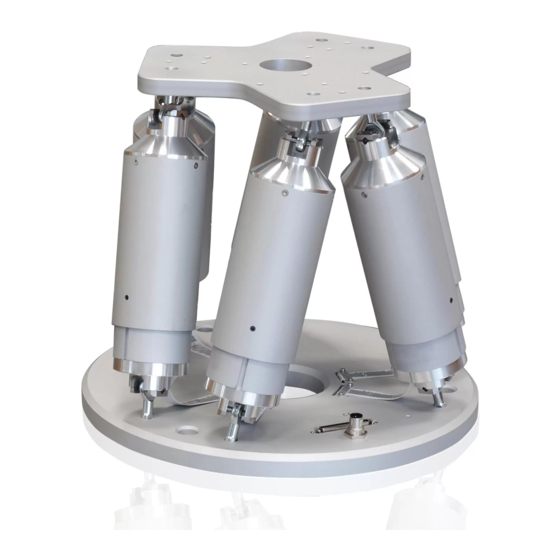
H-820 Hexapod Microrobot
User Manual
Version: 2.3.0
Physik Instrumente (PI) GmbH & Co. KG, Auf der Roemerstrasse 1, 76228 Karlsruhe, Germany
Phone +49 721 4846-0, Fax +49 721 4846-1019, Email info@pi.ws, www.pi.ws
Date: 04.12.2019
This document describes the following product:
H-820.D2
Hexapod microrobot, basis model, 20 mm/s,
20 kg load, Sub-D connector (m), cable set 3 m
Advertisement
Table of Contents

Related Manuals for PI H-820


Summary of Contents for PI H-820
- Page 1 Hexapod microrobot, basis model, 20 mm/s, 20 kg load, Sub-D connector (m), cable set 3 m Physik Instrumente (PI) GmbH & Co. KG, Auf der Roemerstrasse 1, 76228 Karlsruhe, Germany Phone +49 721 4846-0, Fax +49 721 4846-1019, Email info@pi.ws, www.pi.ws...
- Page 2 BiSS is a registered trademark of iC-Haus GmbH. © 2019 Physik Instrumente (PI) GmbH & Co. KG, Karlsruhe, Germany. The text, photographs, and drawings in this manual are protected by copyright. With regard thereto, Physik Instrumente (PI) GmbH & Co. KG retains all the rights.
-
Page 3: Table Of Contents
Contents About this Document Objective and Target Audience of this User Manual..........1 Symbols and Typographic Conventions..............1 Figures ........................2 Other Applicable Documents ..................2 Downloading Manuals ....................3 Safety Intended Use ......................5 General Safety Instructions ..................5 Organizational Measures .................... - Page 4 Startup General Notes on Startup ..................29 Starting Up the Hexapod System ................30 Maintenance Performing a Maintenance Run ................31 Packing the Hexapod for Transport ................31 Cleaning the Hexapod ....................35 Troubleshooting Customer Service Technical Data 10.1 Specifications ......................41 10.1.1 Data Table ....................
-
Page 5: About This Document
Downloading Manuals ........................3 Objective and Target Audience of this User Manual This manual contains information on using the H-820 as intended. It assumes that the reader has a fundamental understanding of basic servo systems as well as motion control concepts and applicable safety procedures. -
Page 6: Figures
Photographic illustrations may also differ and must not be seen as guaranteed properties. Other Applicable Documents The devices and software tools from PI mentioned in this documentation are described in their own manuals. Device/program Document Document content C-887.5xx controller... -
Page 7: Downloading Manuals
If a manual is missing or problems occur with downloading: Contact our customer service department (p. 39). Downloading manuals 1. Open the website www.pi.ws. 2. Search the website for the product number (e.g., P-882) or the product family (e.g., PICMA® bender). -
Page 9: Safety
The H-820 is built according to state-of-the-art technology and recognized safety standards. Improper use can result in personal injury and/or damage to the H-820. Use the H-820 for its intended purpose only, and only when it is in perfect technical condition. - Page 10 Add all information from the manufacturer to the user manual, for example supplements or technical notes. If you give the H-820 to a third party, include this user manual as well as other relevant information provided by the manufacturer.
-
Page 11: Product Description
Technical Features ........................12 Features and Applications The H-820 hexapod achieves a velocity of up to 20 mm/s. It can be loaded with a maximum of 20 kg in a vertical orientation and with a maximum of 10 kg in any other orientation. -
Page 12: Suitable Controllers
EtherCAT interface, motion stop C-887.533 6-axis controller for hexapods, TCP/IP, RS-232, benchtop device, incl. control of two additional axes, EtherCAT interface, motion stop, analog inputs To order, contact our customer service department (p. 39). Version: 2.3.0 MS207E H-820 Hexapod Microrobot... -
Page 13: Product View
Data transmission cable, HD D-sub 78 f/m, 1:1, 3 m Power supply cable, M12m 180° to M12f 90°, 3 m K060B0111 000015165 Steward snap-on ferrite Packaging, consisting of: Inner and outer box Foam and corrugated cardboard cushions Pallet H-820 Hexapod Microrobot MS207E Version: 2.3.0... -
Page 14: Accessories
Power supply cable, M12 m/f, 1:1 K060B0222 C-887.5B05 Hexapod cable set 5 m, drag chain compatible, consisting of: Designation Length Item number Data transmission cable, HD D-sub 78 f/m, 1:1 K040B0271 Power supply cable, M12 m/f, 1:1 K060B0222 Version: 2.3.0 MS207E H-820 Hexapod Microrobot... - Page 15 Short data transmission cable, HD D-sub 78 f/m, K040B0241 Long data transmission cable, HD D-sub 44 f/m, 44 m K040B0277 1:1, three pieces Power supply cable for hexapod-side line driver 47 m K060B0228 box, with M12 connector (m)/M-12 connector (f) H-820 Hexapod Microrobot MS207E Version: 2.3.0...
-
Page 16: Technical Features
3.7.3 Control Der hexapod is intended for operation with a suitable controller from PI (p. 8). The controller makes it possible to command motion of individual axes, combinations of axes or all six axes at the same time in a single motion command. -
Page 17: Motion
A given rotation in space is calculated from the individual rotations in the order U -> V- > W. For further information on the center of rotation, see the glossary (p. 49). H-820 Hexapod Microrobot MS207E Version: 2.3.0... - Page 18 The rotation around the U axis tilts the rotational axes V and W. Figure 3: Rotation around the U axis Platform in reference position Platform position: U = 10 (U parallel to spatially-fixed X axis) Version: 2.3.0 MS207E H-820 Hexapod Microrobot...
- Page 19 The rotation around the V axis tilts the rotational axes U and W. Figure 4: Rotation around the V axis Platform in reference position Platform position: U = 10, V = –10 (U and V parallel to the platform level) H-820 Hexapod Microrobot MS207E Version: 2.3.0...
-
Page 20: Id Chip
(e.g., geometry data and control parameters). The configuration data for customized hexapods is only stored on the controller if the hexapod and controller are delivered together, or if PI was correspondingly informed before delivery of the controller. -
Page 21: Unpacking
7. Compare the contents with the items listed in the contract and the packing list. If any of the parts are wrong or are missing, contact PI immediately. 8. Inspect the hexapod for signs of damage. If there is any sign of damage, contact PI immediately. -
Page 23: Installation
Make sure that no collisions between the hexapod, the load to be moved, and the surroundings are possible in the workspace of the hexapod. H-820 Hexapod Microrobot MS207E Version: 2.3.0... -
Page 24: Determining The Permissible Load And Workspace
PIVeriMove, see the C887T0002 technical note (in the scope of delivery of the software). Determining the Permissible Load and Workspace Tools and Accessories PC with Windows operating system with the PI Hexapod Simulation Tool installed. For further information, see the A000T0068 technical note. -
Page 25: Attaching The Snap-On Ferrite
000015165 snap-on ferrite, included in the scope of delivery of the hexapod (p. 9) 000012097 snap-on ferrite, included in the scope of delivery of a cable set with the line driver boxes (p. 10) H-820 Hexapod Microrobot MS207E Version: 2.3.0... -
Page 26: Grounding The Hexapod
Mounting the Hexapod on a Surface NOTICE Impermissible mechanical load! An impermissible mechanical load can damage the hexapod. Only hold the hexapod by the base plate. Version: 2.3.0 MS207E H-820 Hexapod Microrobot... - Page 27 The arrangement of the mounting holes in the base plate of the hexapod can be found in the dimensional drawing (p. 44) as well as in the corresponding figure. 2. Mount the hexapod on the three mounting holes in the base plate using the M6x30 screws supplied. H-820 Hexapod Microrobot MS207E Version: 2.3.0...
-
Page 28: Fixing The Load To The Hexapod
Only use screws that do not project under the motion platform after being screwed in. Only mount the hexapod and the load on the mounting fixtures (holes) intended for this purpose. Figure 8: M6 mounting holes in the motion platform Version: 2.3.0 MS207E H-820 Hexapod Microrobot... -
Page 29: Optional: Removing The Coordinate Cube
Tools and accessories Hex key AF 2.0 Removing the coordinate cube Figure 9: Removing the Coordinate Cube 1. Loosen the threaded pin M4x8. 2. Pull the coordinate cube upwards away from the base plate. H-820 Hexapod Microrobot MS207E Version: 2.3.0... -
Page 30: Connecting The Hexapod To The Controller
Observe the assignment that is given by the labeling on the sockets, connectors and cables. − Observe the mechanical coding of connectors and sockets. − Do not use force. − Use the integrated screws to secure the connections against accidental disconnection. Version: 2.3.0 MS207E H-820 Hexapod Microrobot... - Page 31 Power adapter, from the scope of delivery of the controller, 24 V DC output Data transmission cable* Power supply cable* * From the scope of delivery of the hexapod (p. 9) or of an optionally available cable set (p. 10). H-820 Hexapod Microrobot MS207E Version: 2.3.0...
- Page 32 Data transmission cable 44 m* Maintain channel assignment! Data transmission cable 3 m** * From the scope of delivery of the cable set (p. 10). ** From the scope of delivery of the hexapod (p. 9). Version: 2.3.0 MS207E H-820 Hexapod Microrobot...
-
Page 33: Startup
Once you have established communication via TCP/IP or RS-232, send the CST? command. The response shows the hexapod, to which the controller is adapted. Only operate the hexapod with a controller whose configuration data is adapted to the hexapod. H-820 Hexapod Microrobot MS207E Version: 2.3.0... -
Page 34: Starting Up The Hexapod System
Starting up the hexapod system 1. Start up the controller (refer to the user manual of the controller). 2. Run a few motion cycles for test purposes (refer to the user manual of the controller). Version: 2.3.0 MS207E H-820 Hexapod Microrobot... -
Page 35: Maintenance
Packing the Hexapod for Transport NOTICE Impermissible mechanical load! Impermissible mechanical load can damage the hexapod. Only ship the hexapod in the original packaging. Only hold the hexapod by the base plate. H-820 Hexapod Microrobot MS207E Version: 2.3.0... - Page 36 5. Grip the hexapod's base plate and put it into the foam insert of the inner box. 6. Put the foam cover onto the hexapod, see figure. Pay attention to the appropriate orientation of the cover. Version: 2.3.0 MS207E H-820 Hexapod Microrobot...
- Page 37 11. Secure the outer box on the pallet with two parallel strapping bands. 12. Wrap the box and pallet with stretch film. Step 4 a Step 4 b Step 4 d Right: Appropriate orientation of the foam insert, view from above H-820 Hexapod Microrobot MS207E Version: 2.3.0...
- Page 38 7 Maintenance Step 6 Right: Appropriate orientation of the foam cover, view from above Step 7 Step 9 Step 10 Version: 2.3.0 MS207E H-820 Hexapod Microrobot...
-
Page 39: Cleaning The Hexapod
You have removed the cables for data transmission and the power supply from the hexapod. Cleaning the hexapod If necessary, clean the surfaces of the hexapod with a cloth that is lightly dampened with a mild cleanser or disinfectant. H-820 Hexapod Microrobot MS207E Version: 2.3.0... -
Page 41: Troubleshooting
E-Stop socket. If you use the "Motion Stop" functionality: 1. Check your system and make sure that the hexapod can be moved safely. 2. Activate the 24 V Out 7 A output H-820 Hexapod Microrobot MS207E Version: 2.3.0... - Page 42 "Make contact" (for details, see user manual for the controller). If you use the C-887.MSB motion- stop-box from PI: Press the mushroom button first to unlock it, then press the green pushbutton. 3. Switch the servo mode on for the hexapod axes.
-
Page 43: Customer Service
9 Customer Service Customer Service For inquiries and orders, contact your PI sales engineer or send us an email (mailto:service@pi.de). If you have any questions concerning your system, provide the following information: − Product and serial numbers of all products in the system −... -
Page 45: Technical Data
±0.5 µm typ. Repeatability θ , θ ±8 µrad typ. Repeatability θ ±25 µrad typ. Backlash X, Y µm typ. Backlash Z µm typ. Backlash θ , θ µrad typ. Backlash θ µrad typ. H-820 Hexapod Microrobot MS207E Version: 2.3.0... -
Page 46: Maximum Ratings
10.1.2 Maximum Ratings The hexapod is designed for the following operating data: Maximum Maximum Maximum operating operating current frequency voltage consumption (unloaded) 24 V DC Version: 2.3.0 MS207E H-820 Hexapod Microrobot... -
Page 47: Cable Set Specifications
Cable Set Specifications The following table lists the technical data of all optionally available cable sets, irrespective of whether they are suitable for the H-820 hexapods. Refer to "Optional Accessories" (p. 10)for a selection of suitable cable sets. Standard cable sets... -
Page 48: Ambient Conditions And Classifications
The (0,0,0) coordinates refer to the origin of the coordinate system. When the default settings for the coordinate system and center of rotation are used, and the hexapod is at the reference position, the center of rotation is located at the origin of the coordinate system. Version: 2.3.0 MS207E H-820 Hexapod Microrobot... -
Page 49: Pin Assignment
CH1 B+ OUT CH1 A- OUT CH1 B- OUT CH2 Sign IN CH2 MAGN IN CH2 Ref OUT CH2 LimP OUT CH2 LimN OUT CH2 A+ OUT CH2 B+ OUT CH2 A- OUT CH2 B- OUT H-820 Hexapod Microrobot MS207E Version: 2.3.0... - Page 50 CH6 MAGN IN CH6 Ref OUT CH6 LimP OUT CH6 LimN OUT CH6 A+ OUT CH6 B+ OUT CH6 A- OUT CH6 B- OUT ID Chip Brake/Enable drive 24 V input Power Good 24 V output Version: 2.3.0 MS207E H-820 Hexapod Microrobot...
-
Page 51: Old Equipment Disposal
Dispose of your old equipment according to international, national, and local rules and regulations. In order to fulfil its responsibility as the product manufacturer, Physik Instrumente (PI) GmbH & Co. KG undertakes environmentally correct disposal of all old PI equipment made available on the market after 13 August 2005 without charge. -
Page 53: Glossary
The X, Y and Z axes are also referred to as translational axes. The intersection of the axes X, Y, and Z of the spatially fixed Cartesian coordinate system (0,0,0) is referred to as the origin. H-820 Hexapod Microrobot MS207E Version: 2.3.0... - Page 54 The Z axis is perpendicular to the base plate of the hexapod. The following example figures of the H-810 hexapod show that the coordinate system does not move along with motion of the platform. Figure 13: H-810 hexapod in the reference position. Cable exit Version: 2.3.0 MS207E H-820 Hexapod Microrobot...
- Page 55 12 Glossary Figure 14: H-810 hexapod, the platform of which has been moved in X. Cable exit H-820 Hexapod Microrobot MS207E Version: 2.3.0...
-
Page 57: Appendix
The following test cycles are performed: Motion over the entire travel range with at least 20 measuring points, in at least five cycles. Motion over partial sections, e.g., ±1 mm in increments of for example, 10 µm H-820 Hexapod Microrobot MS207E Version: 2.3.0... -
Page 59: Eu Declaration Of Conformity
13 Appendix 13.2 EU Declaration of Conformity For the H-820, an EU Declaration of Conformity has been issued in accordance with the following European directives: EMC Directive RoHS Directive The applied standards certifying the conformity are listed below. EMC: EN 61326-1...
Need help?
Do you have a question about the H-820 and is the answer not in the manual?
Questions and answers