Table of Contents
Advertisement
Quick Links
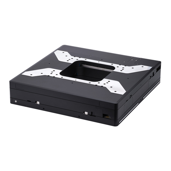
MP183E
L-738 / V-738 Precision XY Stage
User Manual
Version: 1.1.2
PI miCos GmbH, Freiburger Strasse 30, 79427 Eschbach, Germany
Phone +49 7634 5057-0, Fax +49 7634 5057-99, Email info@pimicos.com, www.pi.ws
Date: 17-July-2019
This document describes the following precision
XY stages with 102 mm x 102 mm travel range:
L-738.051100:
With stepper motor, without encoder
L-738.051111:
With stepper motor and linear encoder,
sin/cos signal transmission
L-738.051112:
With stepper motor and linear encoder,
A/B quadrature signal transmission
L-738.053111:
With DC motor and linear encoder,
sin/cos signal transmission
L-738.053112:
With DC motor and linear encoder,
A/B quadrature signal transmission
L-738.053132:
With DC motor and rotary encoder,
A/B quadrature signal transmission
V-738.056111:
With linear motor and linear encoder,
sin/cos signal transmission
Advertisement
Table of Contents


Need help?
Do you have a question about the L-738 Series and is the answer not in the manual?
Questions and answers