Table of Contents
Advertisement
Advertisement
Table of Contents

Related Manuals for Universal Space Squirt A Gator


Summary of Contents for Universal Space Squirt A Gator
- Page 1 (For 4” capsule) Operation Manual www.universal-space.com...
-
Page 2: Important Safety Instructions
Thank you for purchasing Squirt A Gator. We hope you enjoy the product. This manual contains valuable information about how to operate and maintain your game machine properly and safely. It is intended for the owner and/or personnel in charge of product operation. -
Page 3: Important Note
Use the following safety guidelines to help ensure your own personal safety and to help protect your equipment and surrounding environment from potential damage. This product is an indoor game machine. Do not install outdoors. Avoid installing in the following places to prevent fire, electric shock, injury and/or machine malfunctioning: ... - Page 4 CONTENT IMPORTANT SAFETY INSTRUCTIONS ............1 1. SPECIFICATIONS ..................4 2. PACKAGE CONTENTS ................5 3. PART NAME .................... 6 4. SET UP & INSTALLATION ..............7 5. HOW TO PLAY ..................10 6. PARAMETER SETTINGS ..............11 7. ERROR MESSAGE AND RECOVERY ........... 16 8.
-
Page 5: Specifications
1. SPECIFICATIONS Rated power supply: AC110V 50/60Hz Min. Power consumption: 40W Max. Power consumption:980W Dimensions: W1000×D1930×H2090 (mm) Weight: Approximately 225kg NOTICE: After turning off the game, please wait at least 1 minute before restarting again. Note: Game parameters are subject to change without notice. NOTICE: After turning off the game, please wait at least 1 minute before restarting again. -
Page 6: Package Contents
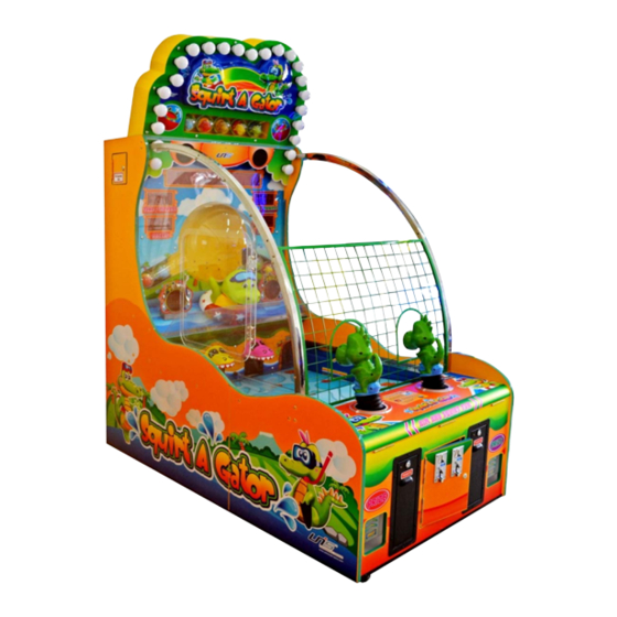
2. PACKAGE CONTENTS Open the package and make sure all the items are included: 1 x Body Assembly Following accessories Part No. Code Name Spec. Picture S117-460-000 23301000001 Power cord 15A/250V 1.8M Φ6×30mm S117-433-000 21901000014 T10A Fuse 250VAC (220V) Φ6×30 T15A S117-432-000 21901000013 250VAC (110V) - Page 7 3. PART NAME Marquee Light Prize window Game information Speaker display Score display Time LED Large gator Prize container Prize light Coin mech. Dino water Gun Ticket dispenser Prize out...
-
Page 8: Setup And Installation
4. SET UP & INSTALLATION This product is an indoor game machine. Do not install outdoors. Refer to IMPORTANT SAFETY INSTRUCTIONS (Pg. 2) for places to avoid Place the unit on a dry level surface Ventilation openings in the back of the unit must not be obstructed by objects or by wall. - Page 9 4.3 Level Adjustment Install this machine on a flat surface. Adjust levers to lift casters off the ground to level the game If the game is installed on an unsuitable floor, it could cause game malfunction. To secure the game, adjust the Leveler down until it touches the floor, lifting the casters off the ground by 5mm.
- Page 10 4.5 Connecting Power WARNING: Check the voltage rating before you connect the equipment to an electrical outlet to ensure that the required voltage and frequency match the available power source. Please refer the label of the machine. Do not plug the equipment power cables into an electrical outlet if the power cable is damaged.
-
Page 11: How To Play
4.6 First Time SET-UP Step 1: After properly setting up the machine on a flat surface, slowly add water into the playfield directly until the water reaches the indicated waterline (See section 8.5 “Adding Water”) Step 2: Take out 12 rubber ducks from the package included and place 6 ducks on each side of the playfield. -
Page 12: Parameter Settings
6. PARAMETER SETTINGS Please refer to the I/O chart and schematics included with the game. To adjust DIP settings, please refer to the I/O chart. The initial settings are in CAPITAL LETTERS. 6.3 Main Board 6.4 Test Display L score LED<1>3-1 R score LED<2>3-1 L ticket LED<1>7-5 L time LED<1>7-5... -
Page 13: Parameter Setting
6.6 Test Mode LED displays 8.7.6.5.4.3.2.1 and 87654321,test LED display is functioning well or not; Press TEST button again and LED displays 1, LED<1>1-2 shows DIP state. Press TEST button again and LED displays 2, it shows the number of on-off SW. Press TEST button again and LED displays 3. - Page 14 SW2_DIP adjust Item Content Score group Play mode Continue credit mode Demo music SW3_DIP adjust Item Content Out of Continue play ticket /Out of Game stop Capsule Score memory SW4_DIP adjust Item Content...
- Page 15 * Score group: Score 1-150 151-300 301-450 451-999 Ticket 0 ticket 0 ticket 0 ticket 1 Capsule 1 ticket 2 tickets 3 tickets 1 Capsule 2 tickets 4 tickets 6 tickets 1 Capsule 5 tickets 8 tickets 12 tickets 1 Capsule 8 tickets 12 tickets 15 tickets...
- Page 16 OUTPUT Content OUTPUT Content OUTPUT Content J26-33 Shell light 1 J4-1 Dot matrix A J2-1 J26-34 Shell light 2 J4-2 Dot matrix B J2-2 J26-35 Shell light 3 J4-3 Dot matrix C J2-3 Marquee LAT J26-36 Capsule meter J4-4 Dot matrix EN J2-4 Marquee CLK J26-37...
-
Page 17: Error Message And Recovery
7. ERROR MESSAGE AND RECOVERY 7.1 Trouble Shootings Please confirm whether every connector connected tightly. Problem Cause Countermeasures Please check power supply suitable for Machine no Power is not supplied. the machine or not. response after power Check leakage SW break or not, if break Leakage SW protection. -
Page 18: Maintenance And Inspection
8. MAINTENANCE & INSPECTION 8.1 Safety Check Check the points listed before operating the machine. These checks are necessary for safe machine operation: 1.Try to run the game before operation each day. 2.Conduct monthly routine checks of game components ensure good working condition 3.Check the machine regularly for dust and clean when necessary. -
Page 19: Regular Cleaning
8.3 How To Open The Control Panel 1. Use key to open the control panel coin mech. service door. Coin mech. service door 2. Put your hand into the service door and loosen the lock pin. Then you should catch 2 Dino water guns and pull them towards you, Control panel should be opened up. - Page 20 8.5 Adding Water 1. When adding water, please turn off the drain valve and lock tightly water pump drain screw, Release drain button. 2. Open up the side service door. Slowly pour water down into the playfield directly until the water reaches the indicated water line.
- Page 21 8.6 Other Parts Maintenance Open the service door which at the back of the machine. 8.6.1 Water pipe maintenances 8.6.2 Sensor maintenances Unscrewed and take Unscrewed and maintenance out water pipe. sensor 8.6.3 Filter maintenances Filter Unscrewed clean up filter 8.7 Pump Assembly Setting ...
-
Page 22: Overall Construction
9. OVERALL CONSTRUCTION 9.1 Main Assembly 1 Part No. Code Name Spec. S117-001-000 29911304001 Cabinet assy. Assy. S117-291-000 26000010000 2.5”castor bracket Q235 δ3(color zinc) S117-472-000 26000008000 2.5” leveller Q235 M16X100(color zinc) S117-471-000 25501000056 2.5”castor 3-2689-52... - Page 23 9.2 Main Assembly 2 Part No. Code Name Spec. S117-207-000 20211304014 Capsule in board Q235 δ1.2 black powder S117-003-000 29911304003 Capsule box assy. Assy. S117-244-000 20211304051 Motor fix board Q235 δ2 black powder 55ZY24-25-02/60JB120G S117-464-000 23404000083 DC motor 0832 S117-224-000 20211304031 L fairway tube Q235 δ1.2 black powder...
- Page 24 9.3 Main Assembly 3 Part No. Code Name Spec. S117-273-000 25101100057 15 copper gas jet DN15 1/2 inch S117-277-000 25101120136 Brake valve DN15 1/2 inch 15 stainless steel T S117-266-000 25101030078 DN15 1/2 inch joint Copper in& out S117-270-000 25101051006 DN15×10 1/2×3/8 screw 2×8mm×DN15 8mm×3/4...
- Page 25 9.4 Main Assembly 4 Part No. Code Name Spec. S117-273-000 25101100057 Copper outer gas jet DN15 1/2 inch S117-266-000 25101030078 15 stainless steel T joint DN15 1/2 inch 15 stainless steel inter S117-271-000 25101070053 DN15 1/2 inch connector S117-272-000 25101080047 Copper faucet DN15 1/2 inch S117-269-000...
- Page 26 9.5 Main Assembly 5 Part No. Code Name Spec. S117-631-000 20611304014 Red gator head Vinyl δ3 S117-613-000 20611106020 R outer track Transparent PVC δ2 S117-630-000 20611304013 Yellow gator head Vinyl δ3 S117-612-000 20611106019 L outer track Transparent PVC δ2 S117-611-000 20611106018 Inner track Transparent PVC δ2...
- Page 27 Part No. Code Name Spec. 25 copper quarter S117-264-000 25101020040 DN25 1” bend S117-185-000 20211106044 Return pipe nut Brass 13 8mm gas -1/4 inch S117-275-000 25101110132 bend S117-214-000 20211304021 R return pipe bracket Stainless steel 304 δ1.5 Back R water cover S117-178-000 20211106034 Stainless steel 304 δ1.2...
- Page 28 9.6 Main Assembly 6...
- Page 29 Part No. Code Name Spec. S117-189-000 20211106048 Water gun fixed board δ2 powder black Cross recess pan head S117-129-000 20101100052 M5×20 screw Return tension spring S117-166-000 20210916031 φ12 powder black clasp pin S117-165-000 20210916030 Return spring φ0.8 color zinc S117-153-000 20106090133 Cylindrical br.
- Page 30 9.7 Main Assembly 7...
- Page 31 Part No. Code Name Spec. S117-189-000 20211106048 Water gun fixed board δ2 powder black Cross recess pan head S117-129-000 20101100052 screw M5×20 Return tension spring S117-166-000 20210916031 clasp pin φ12 powder black S117-165-000 20210916030 Return spring φ0.8 color zinc S117-153-000 20106090133 Cylindrical br.
- Page 32 9.8 Main Assembly 8 Part No. Code Name Spec. S117-240-000 20211304047 Marquee back plate Q235 δ1.5 powder yellow Cross recess pan head S117-111-000 20101020035 Q235 M4×12 color zinc set screw Marquee capsule back S117-239-000 20211304046 Q235 δ2 powder yellow plate Cross recess pan head S117-116-000 20101030040...
-
Page 33: Main Assembly
9.9 Main Assembly 9 Part No. Code Name Spec. S117-280-000 25102000007 Handle 125×16 S117-301-000 26300000004 Hinge 2.5” stainless steel S117-623-000 20611304004 Hinge pad Plexi. δ5 S117-622-000 20611304003 Side door plexi. Plexi, δ5 9.10 Main Assembly 10 Part No. Code Name Spec. - Page 34 9.11 Main Assembly 11 Part No. Code Name Spec. Capsule out Q235 δ1.2 powder S117-241-000 20211304048 mechanism cover black S117-462-000 23313000007 Bushing φ14 Cross recess pan head S117-127-000 20101100040 Stainless steel M4×8 set screw S117-254-000 20211304061 Sensor platen Metalδ1 S117-156-000 20113000055 C level washer Q235 4×1h...
- Page 35 9.12 Main Assembly 12...
- Page 36 Part No. Code Name Spec. S117-195-000 20211304002 R bend Square tube 304 δ1.5 S117-196-000 20211304003 Safety net Q235 powder green S117-706-000 20511304002 Main decal Plexi. 969X880X3 S117-508-000 20311304008 Speaker fix board 9mm whiteδ9 S117-194-000 20211304001 L bend Square tube 304 δ1.5 S117-290-000 26000007000 Ticket box 120...
- Page 37 9.13 Main Assembly 13 Part No. Code Name Spec. S117-287-000 25106020194 8mm gas pipe S117-285-000 25106010013 Metallic tube DN15 1/2” 13×18mm S117-286-000 25106010014 Metallic tube DN25 1” 25×31mm S117-218-000 20211304025 Hose hope SUS304 δ1.2 Hoop pipe fixed S117-288-000 25900021001 Stainless steel φ25mm bracket...
- Page 38 9.14 Main Assembly 14 Part No. Code Name Spec. S117-514-000 20311304014 Wooden assembly top board Yellow MDF S117-505-000 20311304005 Up door board Yellow MDF S117-524-000 20311304024 Back door board Yellow MDF S117-511-000 20311304011 Main decal fix board Yellow MDF...
- Page 39 Part No. Code Name Spec. S117-507-000 20311304007 Back Door 2 Yellow MDF S117-503-000 20311304003 L back side board Yellow plywood S117-597-000 HLEYD-01-06BM Capsule mechanism fix board Yellow MDF S117-515-000 20311304015 Wooden assembly middle board Yellow MDF S117-521-000 20311304021 Water tank L&R fixed board Yellow MDF Water tank front&...
- Page 40 9.15 Electrical Part 1 Part No. Code Name Spec. S117-416-000 21412000001 Terminal 10A/15A/250V black S117-453-000 22601000005 Small rocker SW T125/55 S117-435-000 21902000006 Fuse base R3-11 110V/250V/10A Φ5×20mm T10A S117-434-000 21901000030 Fuse 125VAC S117-459-000 23201000001 Filter YB10A1 10A/250V S117-444-000 22140000004 Solid-state relay SSR-40DA S117-454-000 22601000056...
- Page 41 9.16 Electrical Part 2 Part No. Code Name Spec. S117-431-000 21714000228 Dot matrix PCB Φ3.75 76x304mm S117-428-000 21706000037 2.3" digital board LED23B3.PCB S117-801-000 29710916001 Marquee control PCB LED CON-DDL.PCB(V1.1) S117-805-000 29741321003 Dot matrix control pcb XYWCQ-JKB.PCB(V1.1) S117-422-000 21602000012 Power box MW-S150-24(UL)...
- Page 42 9.17 Electrical Part 3 Part No. Code Name Spec. Ф3 with red S117-442-000 22003000075 Red light with base lampshade S117-418-000 21503000021 Sensor YENOX (NO-5V) S117-461-000 23309000126 Wiring S117-447-000 22401000081 Drainage button Orange S117-802-000 29711106001 Light bar LED48NC.PCB S117-419-000 21503000039 Reception sensor GN-10NT-YR S117-420-000 21503000040...
-
Page 43: Electrical Part
9.18 Electrical Part 4 Part No. Code Name Spec. S117-457-000 23000000006 Meter C-012 12VDC 18CPS S117-429-000 21709000002 POT connection plate VR.PCB S117-452-000 22501000006 S117-451-000 22403000001 POT knob Black S117-449-000 22402030002 Service R button PB:11C02R(green) S117-448-000 22402010002 Service L button PB:11C02R(red) S117-450-000 22402050001 Reset button... - Page 44 10. DECAL Part No. Code Name Spec. S117-705-000 20511304001 Marquee vacuum foam 1140×780×3 S117-706-000 20511304002 Main decal 969×880×3 S117-707-000 20511304003 Light board decal 206×186×5 S117-708-000 20511304004 Front water plate 950×175×3 S117-709-000 20511304005 Bridge opening decal 960×620×3 S117-710-000 20511304006 Capsule door decal 66×75×6 S117-711-000 20511304007...
- Page 45 Part No. Code Name Spec. S117-722-000 20511304018 Instruction label 70×70×0.3 S117-723-000 20511304019 Meter label 50×6 S117-724-000 20511304020 FCC certification 110V nameplate 248×68 S117-725-000 20511304021 Non-certification 110V nameplate 128×68 S117-701-000 20510916021 Notice label 110×41 S117-704-000 20511106033 Water mark label 70X95 S117-703-000 20511106030 Instruction label 4 90×70 S117-702-000 20511106028...
- Page 46 Part No. Code Name Spec. 1 S117-736-000 25600000042 Service information label 1 100×50 2 S117-742-000 25600000067 Service information label 100×60 3 S117-746-000 25600000095 New service label(large) 100X50 4 S117-741-000 25600000066 Fork here for unloading label 144×180 5 S117-740-000 25600000065 Fork here label 105×165 6 S117-739-000 25600000064 Do not fork label...
-
Page 47: Wiring Diagram
Wiring Diagram Top marquee light 1... - Page 48 Have Questions? Contact us! www.universal-space.com International Support Center USA Support Center Tel: +1-905-477-2823 Tel: 972-241-4263 Fax: +1-905-477-2660 Fax: 214-919-4918 Email: service@universal-space.com Email:tsnelling@unisusasupportcenter.com (Contact: Clement Yau) (Contact: Tim Snelling)
Need help?
Do you have a question about the Squirt A Gator and is the answer not in the manual?
Questions and answers