Table of Contents
Advertisement
Instructions
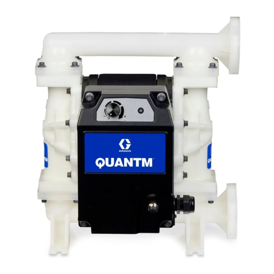
QUANTM
Industrial Models
Electric-operated diaphragm (EODD) pumps with an integral electric drive for fluid
transfer applications. Not for use with hygienic (sanitary) applications. Not for use with
gasoline. For professional use only.
Important Safety Instructions
Read all warnings and instructions in this
manual and related manuals before using
the equipment. Save these instructions.
Pumps,
™
i30 (QTC) Model
i80 (QTD) Model
3A8572B
i120 (QTE) Model
EN
Advertisement
Table of Contents


Need help?
Do you have a question about the QUANTM i30 and is the answer not in the manual?
Questions and answers