Graco Husky 2150 Instruction Manual
Air-operated diaphragm pumps
Hide thumbs
Also See for Husky 2150:
- Instructions and parts list (38 pages) ,
- Instructions-parts list manual (30 pages) ,
- Instructions-parts list manual (34 pages)
Table of Contents
Advertisement
Instructions – Parts List
ALUMINUM, STAINLESS, AND DUCTILE IRON
Husky
Diaphragm Pumps
2-inch AODD pump for fluid transfer applications. For professional use only.
See Models on page 3 for a list of pump models and descriptions.
120 psi (0.8 MPa, 8 bar) Maximum Fluid Working Pressure
120 psi (0.8 MPa, 8bar) Maximum Air Input Pressure
Important Safety Instructions
Read all warnings and instructions in this
manual. Save these instructions.
2150 Air-Operated
TM
308368ZAM
03940B
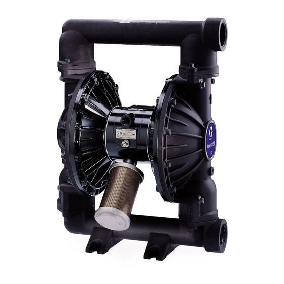
Aluminum Model Shown
EN
Advertisement
Table of Contents

Related Manuals for Graco Husky 2150


Summary of Contents for Graco Husky 2150
- Page 1 Instructions – Parts List ALUMINUM, STAINLESS, AND DUCTILE IRON Husky 2150 Air-Operated Diaphragm Pumps 308368ZAM 2-inch AODD pump for fluid transfer applications. For professional use only. See Models on page 3 for a list of pump models and descriptions. 120 psi (0.8 MPa, 8 bar) Maximum Fluid Working Pressure 120 psi (0.8 MPa, 8bar) Maximum Air Input Pressure Important Safety Instructions Read all warnings and instructions in this...
-
Page 2: Table Of Contents
Performance Chart ......37 Graco Information ......38... -
Page 3: Models
Models Model No. Description *DF3______ Aluminum Pumps *DG3______ Aluminum Pumps, Remote *DFH______ Aluminum Extended Pump *DGH______ Aluminum Extended Pump, Remote *DF4______ Stainless Steel Pumps *DG4______ Stainless Steel Pumps, Remote *DF6______ Ductile Iron Pumps *DG6______ Ductile Iron Pumps, Remote *DFC______ Aluminum BSPT Pumps *DGC______ Aluminum BSPT Pumps, Remote *DFD______... -
Page 4: Symbols
• Never alter or modify any part of this equipment; doing so could cause it to malfunction. Use only genuine Graco parts and accessories. • Check all equipment regularly and repair or replace worn or damaged parts immediately. - Page 5 WARNING HAZARDOUS FLUIDS Improper handling of hazardous fluids or inhaling toxic vapors can cause extremely serious injury, even death, due to splashing in the eyes, ingestion, or bodily contamination. Observe all the following precautions when handling known or potentially hazardous fluids. •...
-
Page 6: Installation
Remember that fittings add friction length to the piping. Reduce the number of fittings to reduce Always use Genuine Graco Parts and Accessories. the friction length. Reference numbers and letters in parentheses refer to c. - Page 7 For ease of operation and service, mount the pump so a true earth ground. Order Part No. 238909 Ground Wire and Clamp. the air valve cover (2), air inlet, and fluid inlet and outlet ports are easily accessible. Rubber Foot Mounting Kit 236452 is available to reduce noise and vibration during operation.
- Page 8 3. Connect remaining ends of tubes to external air A fluid drain valve (J) is required to relieve pressure in signal, such as Graco’s Cycleflo (P/N 195264) or the hose if it is plugged. The drain valve reduces the Cycleflo II (P/N 195265) controllers.
- Page 9 Installation FLOOR-MOUNT TYPICAL INSTALLATION Air supply hose Bleed-type master air valve (required for pump) Air regulator Air line quick disconnect Master air valve (for accessories) Air line filter Fluid suction hose Fluid supply Fluid drain valve (required) Fluid shutoff valve Fluid hose 1/2 npt(f) air inlet port 2 npt(f) fluid inlet port...
- Page 10 Installation Changing the Orientation of the Fluid Inlet Fluid Pressure Relief Valve and Outlet Ports CAUTION Remove and rotate the center manifold(s) to change the orientation of inlet or outlet port(s). Follow Torque Some systems may require installation of a pressure Instructions, page 32.
- Page 11 Installation Air Exhaust Ventilation The air exhaust port is 3/4 npt(f). Do not restrict the air exhaust port. Excessive exhaust restriction can cause erratic pump operation. WARNING If the muffler (P) is installed directly to the air exhaust FIRE AND EXPLOSION HAZARD; port, apply PTFE thread tape or anti-seize thread HAZARDOUS FLUIDS lubricant to the muffler threads before assembly.
-
Page 12: Operation
Operation Flush the Pump Before First Use Operation of Remote Piloted Pumps The pump was tested in water. If water could 1. Fig. 2 and Parts Drawings. Follow preceding steps 1 contaminate the fluid you are pumping, flush it thoroughly through 7 of Starting and Adjusting the Pump. -
Page 13: Maintenance
Maintenance Lubrication Tightening Threaded Connections The air valve is designed to operate unlubricated, Before each use, check all hoses for wear or damage, however if lubrication is desired, every 500 hours of and replace as necessary. Check to be sure all threaded operation (or monthly) remove the hose from the pump connections are tight and leak-free. -
Page 14: Troubleshooting
Troubleshooting WARNING To reduce the risk of serious injury, including splashing fluid in the eyes or on the skin, follow the Pressure Relief Procedure on page 12 when this manual instructs you to relieve pressure, when you shut off the pump, and before checking, adjusting, cleaning, moving, or repairing any system equipment. -
Page 15: Service
Service Repairing the Air Valve Tools Required Torque wrench Torx (T20) screwdriver or 7 mm (9/32”) socket wrench Needle-nose pliers O-ring pick Lithium base grease NOTE: Air Valve Repair Kits 236273 (aluminum center housings) and 255061 (stainless steel center housings) are available. - Page 16 Service Reassembly Insert narrow end first. 1. If you removed the bearings (12, 15), install new ones as explained on page 22. Reassemble the fluid Grease section. Install with lips facing narrow end of piston (11). 2. On aluminum center housing models, install the Insert wide end first.
- Page 17 Notes 308368...
-
Page 18: Ball Check Valve Repair
Service Ball Check Valve Repair Apply medium-strength (blue) thread locker to the threads. Torque to 120 to 150 in-lb (14 to 17 N m) on Tools Required aluminum pumps. Torque to 190-220 in-lb (22-25 N Torque wrench on ductile iron and stainless steel pumps. -
Page 19: Diaphragm Repair
Service Diaphragm Repair Disassembly NOTE: A Fluid Section Repair Kit is available. Refer to page 26 to order the correct kit for your pump. Parts Tools Required included in the kit are marked with an asterisk, for Torque wrench example (401*). - Page 20 Service 4. Loosen but do not remove the diaphragm shaft bolts b. Install the fluid side diaphragm plate (105) on the (107), using a 15 mm socket wrench (1” on stainless bolt so the rounded side faces in, toward the steel models) on both bolts.
- Page 21 Service 402* 403* 401* 03981A 03982A Cutaway View, with Diaphragms in Place Cutaway View, with Diaphragms Removed 401* 403* 108* Lips face out of housing (1). Rounded side faces diaphragm (401). Air Side must face center housing (1). Grease. Apply medium-strength (blue) thread locker. Torque to 20 to 25 ft-lb (27 to 34 N?m) at 100 rpm maximum.
-
Page 22: Bearing And Air Gasket Removal
Service Bearing and Air Gasket Removal Reassembly 1. If removed, install the shaft u-cup packings (402*) so the lips face out of the housing (1). Tools Required Torque wrench 2. The bearings (19, 12, and 15) are tapered and can only be installed one way. - Page 23 Service Insert bearings tapered end first. Press-fit bearings flush with surface of center housing (1) Apply medium-strength (blue) thread locker to the threads. Torque to 120 to 150 in-lb (14 to 17 Nm). 16 H 03951 Detail of Air Valve Bearings 03952B .
-
Page 24: Pump Matrix
Pump Matrix Husky 2150 Aluminum, Stainless Steel, and Ductile Iron Pumps, Series A Your Model No. is marked on the pump’s serial plate. To determine the Model No. of your pump from the following matrix, select the six digits which describe your pump, working from left to right. The first digit is always D, designating Husky diaphragm pumps. - Page 25 * 24B782 Aluminum Pump This pump is the same as Model DF6311 except for the This pump is the same as Model DF3311 except for the serial plate and parts listed in the chart below. serial plate and parts listed in the chart at right. * 25A150 Ductile Iron pump * 24J360 Aluminum Pump This pump is the same as Model DF63G1 except for the...
-
Page 26: Repair Kit Matrix
Part No. 253628: Husky 2150 HD Overmolded PTFE/EPDM Diaphragm Repair Kit. Part No. 289226: Husky 2150 HD Overmolded PTFE/EPDM Diaphragm Repair Kit, with new air side diaphragm plates. Part No. 24F400: Husky 2150 PTFE/Santoprene Backer Diaphragm Repair Kit for Metal Pumps. -
Page 27: Parts
Parts 11 10 Aluminum Model Shown 401* 301* 403* 201* 202* 108* *402 *301 *201 Not used on some models 202* Used on stainless steel model only TI0353B * These parts are included in the Pump Repair Kit, which may Extension be purchased separately. - Page 28 Parts Air Motor Parts List (Matrix Column 2) Ref. Ref. Digit Part No. Description Digit Part No. Description 188838 HOUSING, center; Same as F with the following exceptions 188854 COVER, air valve; alum. 195921 HOUSING, center; 116344 SCREW, mach, hex remote, aluminum flange hd;...
- Page 29 Parts Fluid Section Parts List (Matrix Column 3) Ref. Ref. Digit Part No. Description Digit Part No. Description 15A612 COVER, fluid; aluminum 194279 COVER, fluid; 316 stainless steel 189302 MANIFOLD, inlet; aluminum 194280 MANIFOLD, inlet; 316 stainless steel 15A613 MANIFOLD, outlet; aluminum 194281 MANIFOLD, outlet;...
- Page 30 Parts Fluid Section Parts List (Matrix Column 3) Ref. Ref. Digit Part No. Description Digit Part No. Description 191541 COVER, fluid; ductile iron 15A612 COVER, fluid; aluminum 192088 MANIFOLD, inlet; ductile 192086 MANIFOLD, inlet; iron; BSPT aluminum; BSPT 192089 MANIFOLD, outlet; ductile 15A614 MANIFOLD, outlet;...
- Page 31 Parts Seat Parts List (Matrix Column 4) Ball Parts List (Matrix Column 5) Ref. Ref. Digit Part No. Description Digit Part No. Description 201* 189288 SEAT; 316 stainless steel 301* 112359 BALL; PTFE 202* 112358 O-RING; PTFE 301* 112363 BALL; acetal 201* 189289 SEAT;...
-
Page 32: Torque Instructions
Torque Instructions Aluminum Pumps Ductile Iron and Stainless Steel Pumps Model Numbers DF3___, DG3___, DFH___, DGH___, Model Numbers DF4___, DG4___, DF6___, DG6___, DFC___, DGC___, DFG___, DGG___ DFD___, DGD___, DFF___, DGF___, DV4___, DVD___, DVP___, DVR___ Always follow torque sequence when instructed to torque fasteners. -
Page 33: Dimensions
Dimensions FRONT VIEW PUMP MOUNTING HOLE PATTERN Four 0.625 in. (16 mm) diameter holes 1/2 npt(f) air inlet 3/4 npt(f) air exhaust (muffler included) SIDE VIEW Dimensions B, C, F, G, H, and M 6.25 in. (158.8 can vary by up to 1/4 in. (6.3 mm) depending on the seat and diaphragm material fitted in the 2 in. - Page 34 Pump with Stainless Steel Flanged Manifold Ports SIDE VIEW FRONT VIEW Dimensions B, C, F, G, H, and M can vary by up to 1/4 in. (6.3 mm) depending on the seat and diaphragm material fitted in the pump. 308368...
- Page 35 Dimensions Aluminum Center Aluminum OR SST Aluminum Aluminum Center Aluminum Center Cover Aluminum SST Cover Center SST Center SST Center Aluminum Extended Center Flanged Manifold Cast Iron Aluminum SST Center Cast Iron Cover Pump* SST Cover Ports Cover Cover SST Cover Cover Dimension 12.9...
-
Page 36: Technical Data
Technical Data Maximum fluid working pressure ....................120 psi (0.8 MPa, 8 bar) Air pressure operating range ..............20 to 120 psi (0.14 to 0.8 MPa, 1.4 to 8 bar) Maximum air consumption ..........................175 scfm Air consumption at 70 psi (0.48 MPa, 4.8 bar)/60 gpm ..............60 scfm (see chart) Maximum free-flow delivery...................... -
Page 37: Performance Chart
Performance Chart (4.2) (8.4, 0.84) (3.5) (7, 0.7) (7, 0.7) (5.5, 0.55) (2.8) (4.1, 0.41) (2.1) (1.4) (2.8, 0.28) (1.4, 0.14) (0.7) (lpm) (76) (152) (227) (303) (379) (454) (531) (606) FLUID FLOW (Pump tested in water with inlet submerged) AIR PRESSURE A 120 psi air (8.4 bar, 0.84 MPa) B 100 psi air (7 bar, 0.7 MPa) -
Page 38: Graco Information
With the exception of any special, extended, or limited warranty published by Graco, Graco will, for a period of twelve months from the date of sale, repair or replace any part of the equipment determined by Graco to be defective.
Need help?
Do you have a question about the Husky 2150 and is the answer not in the manual?
Questions and answers