Table of Contents
Advertisement
Quick Links
Instructions – Parts List
STAINLESS STEEL
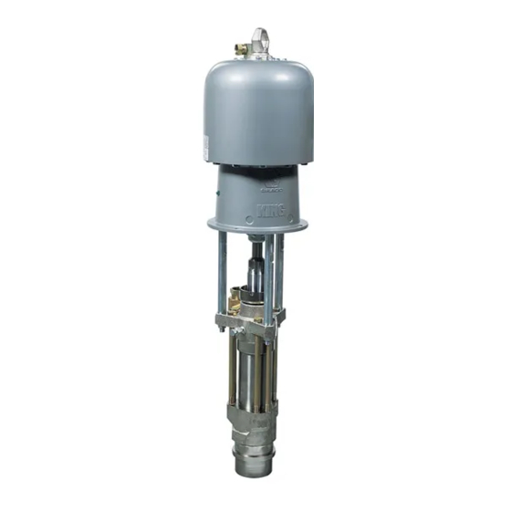
Check–Matet 800 Pumps
With Priming Piston and Severe–Duty Rod and Cylinder
Part No. 236462 Kingt Pump, Series B,
65:1 Ratio, with 236612 Displacement Pump
40 MPa, 403 bar (5850 psi) Maximum Fluid Working Pressure
0.6 MPa, 6.2 bar (90 psi) Maximum Air Input Pressure
Part No. 241519 Quiet Kingt Pump, Series B,
65:1 Ratio, with 236612 Displacement Pump
40 MPa, 403 bar (5850 psi) Maximum Fluid Working Pressure
0.6 MPa, 6.2 bar (90 psi) Maximum Air Input Pressure
Part No. 234978 Bulldogt Pump, Series A,
31:1 Ratio, with 236612 Displacement Pump
40 MPa, 403 bar (5850 psi) Maximum Fluid Working Pressure
0.6 MPa, 6.2 bar (90 psi) Maximum Air Input Pressure
US Patent Nos. 5,147,188 and 5,154,532.
Other Patents Pending.
Important Safety Instructions
Read all warnings and instructions in this manual.
Save these instructions.
Refer to page 2 for Table of Contents.
GRACO INC. P.O. BOX 1441 MINNEAPOLIS, MN 55440–1441
Copyright 1995, Graco Inc. is registered to I.S. EN ISO 9001
Parts
Part No. 236462 Shown
308352D
TI03820
Advertisement
Table of Contents

Related Manuals for Graco King B Series


Summary of Contents for Graco King B Series
- Page 1 Read all warnings and instructions in this manual. Save these instructions. Refer to page 2 for Table of Contents. Part No. 236462 Shown TI03820 GRACO INC. P.O. BOX 1441 MINNEAPOLIS, MN 55440–1441 Copyright 1995, Graco Inc. is registered to I.S. EN ISO 9001...
-
Page 2: Table Of Contents
D Read all instruction manuals, tags, and labels before operating the equipment. D Use the equipment only for its intended purpose. If you are not sure, call your Graco distributor. D Do not alter or modify this equipment. Always use genuine Graco parts and accessories. - Page 3 WARNING SKIN INJECTION HAZARD Spray from the spray gun/dispense valve, leaks or ruptured components can inject fluid into your body and cause extremely serious injury, including the need for amputation. Fluid splashed in the eyes or on the skin can also cause serious injury. D Fluid injected into the skin might look like just a cut, but it is a serious injury.
-
Page 4: Installation
Installation Grounding 2. Air and fluid hoses: use only electrically conductive hoses. WARNING 3. Air compressor: follow manufacturer’s recommen- FIRE AND EXPLOSION HAZARD dations. Before operating the pump, ground the system as explained below. Also read the section FIRE AND EXPLOSION 4. - Page 5 Contact your Graco distributor for assis- tance in designing a system to suit your particular Accessories are available from Graco. If you supply needs. your own accessories, be sure they are adequately sized and pressure-rated to meet the system’s require- ments.
- Page 6 Installation D A pump air bleed valve (E) is required in your System Accessories system to relieve air trapped between it and the air motor when the valve is closed (see the WARNING WARNING at left). Be sure the bleed valve is easily accessible from the pump, and is located downstream from A main air bleed valve (C), pump air bleed valve the air regulator.
-
Page 7: Operation/Maintenance
Now clear the tip/nozzle or hose. Bleed hole must face down. Packing Nut/Wet-Cup Torque to 136–149 N.m (100–110 ft-lb). Before starting, fill the packing nut (2) 1/3 full with Graco Throat Seal Liquid (TSL) or compatible solvent. 03820 Fig. 3 See Fig. 3. 308352... - Page 8 Operation Flush the Pump Before First Use WARNING SKIN INJECTION HAZARD The pump is tested with lightweight oil, which is left in To reduce the risk of fluid injection, do not use to protect the pump parts. If the fluid you are using your hand or fingers to cover the bleed hole on the may be contaminated by the oil, flush it out with a underside of the bleeder valve body (29) when...
- Page 9 Operation Shutdown and Care of the Pump Flush with a fluid that is compatible with the fluid you are pumping and with the wetted parts in your system. Check with your fluid manufacturer or supplier for WARNING recommended flushing fluids and flushing frequency. Always flush the pump before fluid dries on the dis- To reduce the risk of serious injury whenever you placement rod.
-
Page 10: Troubleshooting
Turn on the air just enough to start the pump. If the pump starts when the air is turned on, the obstruction is in the fluid hose or gun. NOTE: If you experience air motor icing, call your Graco distributor. 308352... -
Page 11: Required Tools
Troubleshooting PROBLEM CAUSE SOLUTION Erratic or accelerated Exhausted fluid supply. Refill and prime. pump speed. Fluid is too heavy for pump priming. Use the bleeder valve (see page 8); use a ram. Held open or worn piston valve or seals. Clear the valve; replace the seals. Held open or worn priming piston. -
Page 12: Reconnecting The Displacement Pump
6. Reconnect all hoses. Reconnect the ground wire if it was disconnected. Fill the wet-cup (2) 1/3 full of Graco Throat Seal Liquid or compatible solvent. 7. Turn on the air supply. Run the pump slowly to ensure proper operation. -
Page 13: Displacement Pump Service
Displacement Pump Service Disassembly NOTE: These instructions are written with the pump separating at joint A. If it separates at joints B or C, When disassembling the pump, lay out all the removed disassemble it at that joint, place the intake housing parts in sequence, to ease reassembly. - Page 14 Displacement Pump Service 6. Pull the intake seat (37) and seal (38) out the bottom of the intake valve housing (17). Take care not to drop the check valve assembly (V) as it comes free, and set it aside for later. See Fig. 5. NOTE: If the seat (37) is difficult to remove, insert a See Fig.
- Page 15 Displacement Pump Service 9. Remove the seal (8) from the bottom of the cylin- NOTE: The seal (39) is press-fit in the nut (15) and der (10). See Fig. 10. Shine a light into the cylinder may require cutting to ease removal. to examine the inside surface for scoring or dam- age.
- Page 16 Displacement Pump Service Reassembly 4. Lubricate the piston seal (13*) and install it on the piston seat (14). Screw the piston guide (11) onto Fig. 13 shows a cutaway of the entire pump. the seat (14). Place the guide in a vise as shown in Fig.
- Page 17 Displacement Pump Service 7. If the cylinder (10) was removed from the outlet 11. Lubricate the seal (8*) and install it on the bottom housing (9), lubricate the seal (8*) and place it on of the cylinder (10). Slide the intake valve housing the top of the cylinder.
- Page 18 Displacement Pump Service THROAT PACKING DETAIL Piston check valve (see Fig. 10). Intake check valve (see Fig. 11). Lubricate. Lips of v-packings must face down. Screw valve plug (20) completely into valve body (29). Torque to 136–149 N.m (100–110 ft-lb). Torque to 203–237 N.m (150–175 ft-lb).
- Page 19 Displacement Pump Service 15. Screw the intake cylinder (19) into the intake 17. Check that the flats of the priming piston rod (18) housing (17). Using a pipe wrench on the hex of are accessible below the intake cylinder (19). If the cylinder (19), torque the cylinder to 522–542 not, tap on the top of the displacement rod (1) with N.m (385–400 ft-lb).
- Page 20 Notes 308352...
-
Page 21: Parts
Parts Part No. 236462 Pump, Series B, 65:1 Ratio, with King Air Motor (shown) Part No. 241519 Pump, Series B, 65:1 Ratio, with Quiet King Air Motor Part No. 234978 Pump, Series A, 31:1 Ratio, with Bulldog Air Motor Ref. Part No. - Page 22 Parts Model 236612, Series A Displacement Pump 03818 308352...
- Page 23 Parts Model 236612, Series A Displacement Pump Part Part Description Description 189317 ROD, displacement; stainless steel 189516 CYLINDER, intake; stainless steel 236582 PACKING NUT/WET-CUP; 190293 PLUG, bleeder valve; stainless steel stainless steel 276378 PISTON, priming; stainless steel 189645 HOUSING, throat packing; 190241 SEAT, priming piston;...
-
Page 24: Technical Data And Performance Chart
Technical Data Models 236462 and 241519 WARNING Be sure that all fluids and solvents used are chemically compatible with the Wetted Parts listed below. Always read the manufacturer’s literature before using fluid or solvent in this pump. Category Data Ratio 65:1 Maximum fluid working pressure 40 MPa, 403 bar (5850 psi) - Page 25 Technical Data Models 236462 and 241519 Performance Charts To find Fluid Outlet Pressure (psi/MPa/bar) at a specific fluid flow To find Pump Air Consumption (m#/min or scfm) at a specific fluid (lpm/gpm) and operating air pressure (psi/MPa/bar): flow (lpm/gpm) and air pressure (psi/MPa/bar): 1.
- Page 26 Technical Data Model 234978 WARNING Be sure that all fluids and solvents used are chemically compatible with the Wetted Parts listed below. Always read the manufacturer’s literature before using fluid or solvent in this pump. Category Data Ratio 31:1 Maximum fluid working pressure 21 MPa, 214 bar (3100 psi) Maximum air input pressure 0.7 MPa, 7 bar (100 psi)
- Page 27 Technical Data Model 234978 Performance Charts To find Fluid Outlet Pressure (psi/MPa/bar) at a specific fluid flow To find Pump Air Consumption (m#/min or scfm) at a specific fluid (lpm/gpm) and operating air pressure (psi/MPa/bar): flow (lpm/gpm) and air pressure (psi/MPa/bar): 1.
- Page 28 Notes 308352...
-
Page 29: Dimensions
Dimensions and Mounting Hole Layout 94.28 mm (3.712 in.) 101.6 mm 94.28 mm (4.0 in.) (3.712 in.) 50.8 mm (2.0 in.) Three M16 x 2.0 Holes 11.1 mm (0.437 in.) 88 mm DIA (4) (3.464 in.) 0653 03820 Pump Model 236462 1376.7 mm 583.0 mm... -
Page 30: Graco Standard Warranty
Graco distributor to the original purchaser for use. With the exception of any special, extended, or limited warranty published by Graco, Graco will, for a period of twelve months from the date of sale, repair or replace any part of the equipment determined by Graco to be defective.
Need help?
Do you have a question about the King B Series and is the answer not in the manual?
Questions and answers