Table of Contents
Advertisement
Quick Links
Instructions, Limited Release
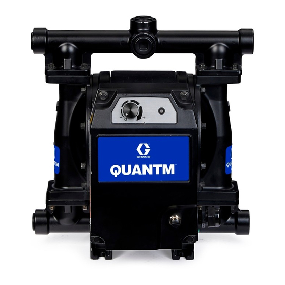
QUANTM
Electric-operated diaphragm (EODD) pumps with an integral electric drive for fluid
transfer applications. Not for use with gasoline. Not approved for use in explosive
atmospheres or hazardous (classified) locations. For professional use only.
Industrial and Hygienic Models
See pages 6–10 for model information.
See pages 63–67 for maximum working pressure and electrical ratings.
Important Safety Instructions
Read all warnings and instructions in this
manual and related manuals before using
the equipment. Save these instructions.
Pumps
™
Q-C Model
Industrial model shown
Q-D Model
Industrial model shown
3A8947A
Q-E Model
Industrial model shown
EN
Advertisement
Table of Contents

Related Manuals for Graco QUANTM QTC Series


Summary of Contents for Graco QUANTM QTC Series
- Page 1 Instructions, Limited Release QUANTM Pumps ™ 3A8947A Electric-operated diaphragm (EODD) pumps with an integral electric drive for fluid transfer applications. Not for use with gasoline. Not approved for use in explosive atmospheres or hazardous (classified) locations. For professional use only. Industrial and Hygienic Models See pages 6–10 for model information.
-
Page 2: Table Of Contents
Flush the Equipment ..... 28 Graco Standard Warranty....68 Store the Equipment . -
Page 3: Warnings
Warnings Warnings The following warnings are for the setup, use, grounding, maintenance, and repair of this equipment. The exclamation point symbol alerts you to a general warning and the hazard symbols refer to procedure-specific risks. When these symbols appear in the body of this manual or on warning labels, refer back to these Warnings. Product-specific hazard symbols and warnings not covered in this section may appear throughout the body of this manual where applicable. - Page 4 Warnings WARNING EQUIPMENT MISUSE HAZARD Misuse can cause death or serious injury. • Do not operate the unit when fatigued or under the influence of drugs or alcohol. • Do not exceed the maximum working pressure or temperature rating of the lowest rated system component.
- Page 5 Warnings WARNING PRESSURIZED ALUMINUM PARTS HAZARD Use of fluids that are incompatible with aluminum in pressurized equipment can cause serious chemical reaction and equipment rupture. Failure to follow this warning can result in death, serious injury, or property damage. • Do not use 1,1,1-trichloroethane, methylene chloride, other halogenated hydrocarbon solvents or fluids containing such solvents.
-
Page 6: Configuration Matrix
Configuration Matrix Configuration Matrix Record the model part number and configuration sequence found on your equipment identification plate (ID) to assist you when ordering replacement parts. Model Part Number: _______________________________________________ Configuration Sequence: _______________________________________________ Sample Configuration Sequence: QTC-ACFC1ACACBNBNA10021 Brand Application Model Wetted Motor Seat Check Diaphragm... - Page 7 Configuration Matrix Motor Cord/Cable Input Drive Coat Phase Location Voltage Termination Aluminum Direct Black powder 200–240 V 3-Phase Industrial, Ordinary Locations Cord with plug Drive coat Aluminum Direct Black powder 200–240 V Single-Phase Industrial, Ordinary Locations Cord with plug Drive coat Aluminum Direct Black powder...
- Page 8 Configuration Matrix Seat Material Check Material Diaphragm Material Manifold Seal Material Acetal Acetal, ball BN Buna-N None Aluminum Buna-N, ball CO Polychloroprene BN Buna-N Overmold BN* Buna-N Polychloroprene, CR Polychloroprene EPDM standard, ball Fluoroelastomer Polychloroprene, EO EPDM Overmold Fluoroelastomer weighted, ball Flapper, for hygienic EPDM, ball Fluoroelastomer...
- Page 9 Configuration Matrix Connection Options Material Certifications Aluminum, standard ports, NPT Standard EN 10204 type 2.1 Aluminum, standard ports, BSP Drum Pump EN 10204 type 3.1 A26 Aluminum, standard ports, BSP, no plugs Flapper, horizontal AC3 Acetal, standard ports, NPT OD Open Down Port AC4 Acetal, standard ports, BSP OR Outlet Reversed Conductive Polypropylene, center flange...
-
Page 10: Approvals
Approvals Approvals Model Information* Approvals For motor approvals, see your Motors related motor manual. See Related Manuals, page 2. All pump models are approved to: QH models with diaphragm materials coded PO combined with PT or FL EC 1935/2004 checks comply with: EC 1935/2004 QH models with diaphragm materials coded EO, PT, or PS combined with EP, PT, or FL checks comply with:... -
Page 11: Component Identification
Component Identification Component Identification . 1: Component Identification (QTC Industrial model shown) Models include a cord with a plug and Input/Output (I/O) port. Ref. Component Description Power Cord/Cable 15 ft (4.6 m) cord with plug* I/O Port/Cable On/Off Control, Digital Input M12, 5-pin connector** Error Status, Digital Output Speed Control, Analog Input... -
Page 12: Typical Installation
Typical Installation Typical Installation General Information Always use Genuine Graco Parts and accessories. Be sure all accessories are adequately sized and A typical installations is shown in F . 2. The figure is pressure-rated to meet the requirements of the system. -
Page 13: Installation
Installation Installation Installation of this equipment involves potentially hazardous procedures. Only trained and qualified personnel who have read and who understand the information in this manual should install this equipment. To avoid injury from fire, explosion, or electric shock, all electrical wiring must be done by a qualified electrician and comply with all local codes . -
Page 14: Install Accessories
Installation Install Accessories If a leak sensor is not installed in the pump, install the following accessory as shown in F . 4, using adapters as needed. Install Monitoring Accessories NOTE: To monitor for leaks in the pump due to Install the following accessory to monitor equipment diaphragm rupture, install a leak sensor. -
Page 15: Grounding
Installation Grounding Connect the Electrical Ground Ground through the provided power cord and plug. Connect the plug to a power outlet that is properly installed and grounded to a true earth ground. Ground the Fluid Lines The equipment must be grounded to reduce the risk of static sparking and electric shock. -
Page 16: Before First Use
Installation Before First Use Tighten Fasteners Before using the equipment for the first time, check and torque all fasteners. Follow Torque Fasteners, page 43. After the first day of operation, re-torque the fasteners. NOTICE To avoid pump damage, do not over-torque the fasteners on the equipment. -
Page 17: Electrical Connections And Wiring
Connect to a circuit with a main electrical disconnect. Install a branch circuit protective device in each ungrounded phase. Follow local codes and regulations. Adapter plugs are available from Graco. See the table on the next page for available adapter kits by region. 3A8947A... - Page 18 242001 15G958 Australia/China 242005 17A242 242002 Italy 15G959 Switzerland 242003 15G961 Denmark 242003 * A C14 plug retainer clip (195551) can be purchased separately from Graco. ‡ A C20 plug retainer clip (121249) can be purchased separately from Graco. 3A8947A...
-
Page 19: I/O Pin Connection
Electrical Connections and Wiring I/O Pin Connection NOTE: All I/O connectors are capable of 30 VDC (volts of direct current) and are reverse-polarity protected. For wiring, see Equivalent Electrical Circuits for I/O Pin Connection, page 20. To avoid injury from fire, explosion, or electric shock, all electrical wiring must be done by a qualified electrician and comply with all local codes and regulations. - Page 20 Electrical Connections and Wiring Equivalent Electrical Circuits for I/O Pin Connection Equivalent Electrical Circuits for I/O Pin Equivalent Electrical Circuits for I/O Pin Connection Connection I/O Circuit Equivalent Circuit I/O Circuit Equivalent Circuit Digital M12, Digital Input 5 VDC Output Pin 2 Kiloohms Maximum 30 VDC,...
-
Page 21: Operation
Operation Operation Pressure Relief Procedure Before Each Use Follow the Pressure Relief Procedure whenever Tighten Fasteners you see this symbol. Check and tighten all fasteners before operating the equipment. Re-torque as needed. Follow Torque Fasteners, page 43. This equipment stays pressurized until pressure is NOTICE manually relieved. -
Page 22: Start The Equipment
Operation Start the Equipment 1. Loosen the four cover screws and remove the control cover (2). 2. Locate the auto-prime dip switch directly below the Prepare the Equipment for Startup leak sensor, and push the dip switch left to disable 1. -
Page 23: Shut Down The Equipment
Operation b. Reduce the number of fittings on the suction lines to reduce friction length. c. Increase the diameter of the suction lines. d. Reduce the fluid inlet pressure. An inlet pressure supply of 3–5 psi (21–35 kPa, 0.2–0.3 bar) is adequate for most materials. NOTICE To avoid pump damage and inefficient operation, do not use a fluid inlet pressure greater than 25 percent of... -
Page 24: Led Indicator
LED Indicator LED Indicator LED Indicator Overview LED Indicator Equipment Status Notes Red, solid Control knob set at 0 (zero), system Be aware that the equipment is energized. not operating. To initiate equipment operation, follow Start the Powered on after a power cycle, Equipment, page 22. -
Page 25: Troubleshoot Led Indicator Event Errors
LED Indicator Troubleshoot LED Indicator Event Errors If an event error occurs, the LED Indicator will blink a set number of times corresponding to the event code that needs acknowledged. 1. Follow the Pressure Relief Procedure, page 21, before checking or repairing the equipment. 2. - Page 26 LED Indicator Troubleshoot LED Indicator Event Errors LED Indicator Problem Cause Solution Yellow, *Leak sensor alert. Leak detected in the equipment. Check the diaphragm for rupture or flashing, incorrect installation. Repair or continuous replace. flash The leak sensor disconnected. Ensure the leak sensor is properly installed.
-
Page 27: Maintenance
NOTICE Lubricate the motor rotor when replacing diaphragms. Regularly maintain the equipment to avoid pump Graco recommends Lubriplate Synxtreme HD Series damage due to spills, leaks, or diaphragm failure. HD-2 grease, or equivalent NLGI grade 2 synthetic bearing grease containing calcium sulfanate complex Establish a preventive maintenance schedule based on as the thickener. -
Page 28: Flush The Equipment
Maintenance Flush the Equipment Store the Equipment Always relieve the pressure and flush the equipment before storing the equipment for any length of time. 1. Follow Pressure Relief Procedure, page 21. To avoid fire and explosion, always ground the equipment and waste container. To avoid static 2. - Page 29 Maintenance Clean In-Place (CIP) Clean Out-of-Place (COP) 1. Follow Pressure Relief Procedure, page 21. NOTICE 2. Flush the equipment with a compatible solvent or To avoid equipment damage, only use cleaning sanitizing solution. Follow Flush the Equipment, fluids that are compatible with materials of the page 28.
-
Page 30: Troubleshooting
Troubleshooting Troubleshooting 1. Follow the Pressure Relief Procedure, page 21, before checking or repairing the equipment. 2. Check all possible problems and causes before disassembling equipment. Problem Cause Solution LED light flashing Equipment error; special-case cause. See Troubleshoot LED Indicator Event Errors, page 25. - Page 31 Troubleshooting Problem Cause Solution Air bubbles in fluid Fluid line is loose. Tighten. Diaphragm (or backup diaphragm, if Replace. applicable) ruptured. Loose manifolds. Tighten manifold fasteners or clamps. Damaged seats or seals. Replace seats or seals. Loose diaphragm shaft fastener. Tighten.
-
Page 32: Repair
Repair Repair Prepare Equipment for Repair NOTE: Repair kits are available (purchase separately). To avoid injury from fire, explosion, or electric shock, all electrical wiring must be done by a qualified electrician and comply with all local codes This equipment stays pressurized until pressure is and regulations. -
Page 33: Repair The Check Valves
Repair Repair the Check Valves 5. For QT (Industrial) Models: On the inlet manifold (5), remove all fasteners (6). Required Tools: For QH (Hygienic) Models: On the inlet manifold (5), remove all clamps (7a). • 10 mm socket wrench (for all QTC models and QTD,E plastic models) 6. - Page 34 Repair For QH Models: Lubricate clamps (7a) and For QTC models: Torque to 100 in-lb (11 N•m). seals (10) with a waterproof, sanitary lubricant. For QTD plastic models: Torque to 80–90 in-lb (9–10 N•m). For QTD metal models: Torque to 120–150 in-lb (14–17 N•m).
-
Page 35: Repair The Standard Diaphragms
Repair Repair the Standard Diaphragms Required Tools: • 10 mm socket wrench (for all QTC models and QTD,E plastic models) • 13 mm socket wrench (for QTD,E metal models) • Torque wrench • 25 mm open-end wrench • Lubriplate Synxtreme HD Series HD-2 grease, or equivalent NLGI grade 2 synthetic bearing grease containing calcium sulfanate complex as the thickener... - Page 36 Repair 5. Remove the fastener (15), seal (16), fluid plate (11), c. Use an applicable wrench to firmly hold the flat diaphragm (13), and diaphragm backer (14) from of the shaft (1a). At the same time, use an the shaft (1a) on the side of the pump where the applicable wrench to loosen the remaining fastener (15) was loosened.
- Page 37 Repair Lubricate the Rotor 1. Follow Prepare Equipment for Repair, page 32. 2. Follow Disassemble Check Valves, page 33. 3. Follow Repair the Standard Diaphragms, page 35, or Repair the Overmolded Diaphragms, page 40. 4. Install the grease tool, without the removable collar, to the exposed side of the shaft (1a).
- Page 38 Repair Reassemble the Standard Diaphragms Apply a high-strength thread locker to attach the fastener to the diaphragm plate. NOTICE Apply a medium-strength thread locker to the shaft After reassembly, allow the thread locker to cure for side of the fastener to attach the diaphragm to the 12 hours, or per instructions of the manufacturer, shaft.
- Page 39 Repair 4. For QT (Industrial) Models: Align the fluid covers (3) to the motor (1). Install fasteners (6, 7, if Torque to 50 ft-lb (68 N•m). applicable) to hold the fluid covers (3) in place. For QTC models: Torque to 110 in-lb (12 N•m). Hand-tighten the fasteners (6, 7, if applicable).
-
Page 40: Repair The Overmolded Diaphragms
Repair Repair the Overmolded NOTICE Diaphragms To avoid damage to the rotor or equipment, do not remove the shaft with plate (1b) from the motor (1). Required Tools: Removing the shaft will cause the rotor balls to dislodge from the rotor and the rotor will not function •... - Page 41 Repair Reassemble the Overmolded Diaphragms Apply a medium-strength thread locker to the shaft side of the fastener to attach the diaphragm to the NOTICE shaft. After reassembly, allow the thread locker to cure for 12 hours, or per instructions of the manufacturer, prior to operating the equipment.
-
Page 42: Recycling And Disposal
Recycling and Disposal tighten the fasteners (6, 7, if applicable) or clamps (6a). 4. For QT (Industrial) Models: Torque all fasteners (6, 7, if applicable). Follow Torque Fasteners, page 5. Reassemble the check valves and manifolds as explained in Reassemble Check Valves, page 33. Recycling and Disposal End of Equipment Life At the end of the useful life of the equipment,... -
Page 43: Torque Fasteners
Torque Fasteners Torque Fasteners Torque Instructions Torque Sequence To ensure proper sealing, torque fasteners using the For QT (Industrial) Models only: Fully torque all following procedure. fasteners (6, 7, if applicable) on the fluid covers (3) before torquing the fasteners (6) on the manifolds (4, 5). 1. - Page 44 Torque Fasteners Torque Sequence for QTD Models Fluid Covers (3) Manifolds (4, 5) Torque fasteners (6, 7 if applicable) to 190–220 in-lb For QTD plastic models: Torque fasteners (6) to (21–25 N•m). 80–90 in-lb (9–10 N•m). For QTD metal models: Torque fasteners (6) to 120–150 in-lb (14–17 N•m).
- Page 45 Torque Fasteners Torque Sequence for QTE Models Fluid Covers (3) Manifolds (4, 5) Torque fasteners (6, 7 if applicable) to 190–220 in-lb For QTE plastic models: Torque fasteners (6) to (21–25 N•m). 150–160 in-lb (17–18 N•m). For QTE aluminum models: Torque fasteners (6) to 120–150 in-lb (14–17 N•m).
-
Page 46: Performance Charts
Performance Charts Performance Charts Performance Chart for Q-C Models (7.0, 0.70) (6.2, 0.62) (5.5, 0.55) (4.8, 0.48) (4.2, 0.42) (3.5, 0.35) (2.8, 0.28) (2.1, 0.21) (1.4, 0.14) (0.7, 0.07) (19) (38) (57) (76) (95) (114) (133) (151) Flow (gpm (lpm)) 3A8947A... -
Page 47: Performance Chart For Q-D Models
Performance Charts Performance Chart for Q-D Models (7.0, 0.70) (6.2, 0.62) (5.5, 0.55) (4.8, 0.48) (4.2, 0.42) (3.5, 0.35) (2.8, 0.28) (2.1, 0.21) (1.4, 0.14) (0.7, 0.07) (38) (76) (114) (151) (190) (227) (265) (303) Flow (gpm (lpm)) Performance Chart for Q-E Models (4.2, 0.42) (3.5, 0.35) (2.8, 0.28) -
Page 48: Dimensions
Dimensions Dimensions Dimensions for QTC Models . 27: QTC Industrial Model Dimensions 3A8947A... - Page 49 Dimensions QTC Model Dimensions Wetted Section Material SS, HT CP, PP, PV Ref. 13.90 35.31 15.20 38.61 14.70 37.34 6.58 16.71 8.00 20.32 7.35 18.67 13.25 33.66 13.25 33.66 13.25 33.66 4.57 11.61 4.57 11.61 4.57 11.61 13.70 34.80 17.80 45.21 15.94 40.49...
-
Page 50: Dimensions For Qhc Models
Dimensions Dimensions for QHC Models . 28: QHC Hygienic Model Dimensions (FG model shown) 3A8947A... - Page 51 Dimensions . 29: QHC Hygienic Model Dimensions (HS model shown) 3A8947A...
- Page 52 Dimensions QHC Model Dimensions Wetted Section Material HS, PH, 3A Ref. 16.30 41.40 13.70 34.80 – – – – – – 6.85 17.40 13.60 34.54 13.25 33.66 4.65 11.81 4.57 11.61 16.10 40.90 19.43 49.35 15.12 38.40 18.43 46.81 2.00 5.08 2.77 7.04...
-
Page 53: Dimensions For Qtd Models
Dimensions Dimensions for QTD Models . 30: QTD Industrial Model Dimensions 3A8947A... - Page 54 Dimensions QTD Model Dimensions Wetted Section Material PP, PV Ref. 15.07 38.28 16.10 40.89 17.60 44.70 13.81 35.08 13.85 35.18 13.87 35.23 5.17 13.13 5.21 13.23 5.23 13.28 19.60 49.78 18.97 48.18 22.00 55.88 18.30 46.48 17.75 45.09 19.30 49.02 1.50 3.81 1.44...
-
Page 55: Dimensions For Qhd Models
Dimensions Dimensions for QHD Models . 31: QHD Hygienic Model Dimensions (FG model shown) 3A8947A... - Page 56 Dimensions . 32: QHD Hygienic Model Dimensions (HS model shown) 3A8947A...
- Page 57 Dimensions QHD Model Dimensions Wetted Section Material HS, PH, 3A Ref. 19.50 49.53 17.00 43.18 – – – – – – 8.50 21.60 14.17 36.00 13.85 35.18 5.22 13.26 5.22 13.26 20.54 52.17 32.55 82.68 19.28 48.97 31.54 80.11 2.44 6.20 9.53 24.21...
-
Page 58: Dimensions For Qte Models
Dimensions Dimensions for QTE Models . 33: QTE Industrial Model Dimensions 3A8947A... - Page 59 Dimensions QTE Model Dimensions Wetted Section Material CI, SS CP, PP, PV Ref. 17.50 44.45 18.13 46.05 19.70 50.04 9.00 22.86 9.40 23.88 11.00 27.94 14.89 37.82 14.89 37.82 14.89 37.82 6.25 15.88 6.25 15.88 6.25 15.88 23.60 59.94 26.34 66.90 25.70 65.28...
-
Page 60: Dimensions For Qhe Models
Dimensions Dimensions for QHE Models . 34: QHE Hygienic Model Dimensions (FG model shown) 3A8947A... - Page 61 Dimensions . 35: QHE Hygienic Model Dimensions (HS model shown) 3A8947A...
- Page 62 Dimensions QHE Model Dimensions Wetted Section Material HS, PH, 3A Ref. 21.07 53.52 19.30 49.02 – – – – – – 9.65 24.51 15.28 38.81 14.89 37.82 6.33 16.08 6.33 16.08 25.95 65.91 35.31 89.69 24.40 61.98 34.05 86.49 2.50 6.35 7.09 18.01...
-
Page 63: Technical Specifications
Technical Specifications Technical Specifications Fluid Temperature Range NOTICE Temperature limits are based on mechanical stress only. Certain chemicals will further limit the fluid temperature range. Stay within the temperature range of the most-restricted wetted component. Operating at a fluid temperature that is too high or too low for the components of your pump may cause equipment damage. Fluid Temperature Range by Wetted Section Material Material of Wetted Contact Section Parts... -
Page 64: Technical Specifications For Q-C Models
Technical Specifications Technical Specifications for Q-C Models QUANTM Q-C Pumps Metric Maximum fluid working pressure 100 psi 6.89 bar, 0.69 MPa Maximum fluid temperature 150°F 65°C Maximum free-flow delivery 30 gpm 114 lpm Maximum size pumpable solids High Sanitation models 0.42 in. 20.7 mm All other models 1/8 in. -
Page 65: Technical Specifications For Q-D Models
Technical Specifications Technical Specifications for Q-D Models QUANTM Q-D Pumps Metric Maximum fluid working pressure 100 psi 6.89 bar, 0.69 MPa Maximum fluid temperature 150°F 65°C Maximum free-flow delivery 60 gpm 227 lpm Maximum size pumpable solids High Sanitation models, ball checks 0.5 in. 12.7 mm High Sanitation models, flapper checks 1.2 in. -
Page 66: Technical Specifications For Q-E Models
Technical Specifications Technical Specifications for Q-E Models QUANTM Q-E Pumps Metric Maximum fluid working pressure 60 psi 6.89 bar, 0.69 MPa Maximum fluid temperature 150°F 65°C Maximum free-flow delivery 100 gpm 378.5 lpm Maximum size pumpable solids High Sanitation models 0.5 in. 12.7 mm All other models 0.25 in. - Page 67 Technical Specifications QUANTM Q-E Pumps Metric Weight Models with wetted section materials coded: AL 99 lb 44.9 kg CI 165 lb 74.8 kg SS 162 lb 73.5 kg CP, PP 100 lb 45.4 kg PV 117 lb 53.0 kg FG 170 lb 77.1 kg HS, PH, 3A 143 lb 64.9 kg...
-
Page 68: Graco Standard Warranty
With the exception of any special, extended, or limited warranty published by Graco, Graco will, for a period of twelve months from the date of sale, repair or replace any part of the equipment determined by Graco to be defective.
Need help?
Do you have a question about the QUANTM QTC Series and is the answer not in the manual?
Questions and answers