Table of Contents
Advertisement
Quick Links
Instructions
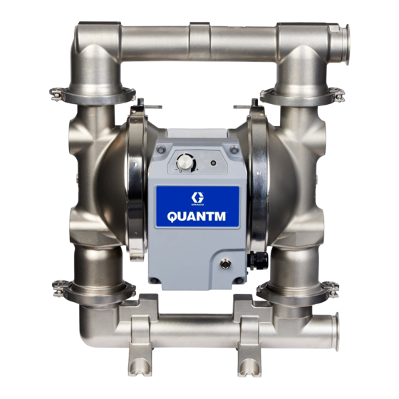
QUANTM
Hygienic Models
Electric-operated diaphragm (EODD) pumps with an integral electric drive for fluid
transfer applications. Not for use with gasoline. For professional use only.
Important Safety Instructions
Read all warnings and instructions in this
manual and related manuals before using
the equipment. Save these instructions.
Pumps,
™
h30 (QHC) Model
h80 (QHD) Model
3A9286C
h120 (QHE) Model
EN
Advertisement
Table of Contents

Subscribe to Our Youtube Channel
Related Manuals for Graco QUANTM h30 QHS: QUANTM h80 QHD


Summary of Contents for Graco QUANTM h30 QHS: QUANTM h80 QHD
- Page 1 Instructions QUANTM Pumps, ™ Hygienic Models 3A9286C Electric-operated diaphragm (EODD) pumps with an integral electric drive for fluid transfer applications. Not for use with gasoline. For professional use only. Important Safety Instructions Read all warnings and instructions in this manual and related manuals before using the equipment.
-
Page 2: Table Of Contents
Shut Down the Equipment....24 Graco Standard Warranty....54 LED Indicator . -
Page 3: Warnings
Warnings Warnings The following warnings are for the setup, use, grounding, maintenance, and repair of this equipment. The exclamation point symbol alerts you to a general warning and the hazard symbols refer to procedure-specific risks. When these symbols appear in the body of this manual or on warning labels, refer back to these Warnings. Product-specific hazard symbols and warnings not covered in this section may appear throughout the body of this manual where applicable. - Page 4 Warnings WARNING ELECTRIC SHOCK HAZARD Explosive Atmospheres or Hazardous (Classified) Locations Models (hard wired for permanent connection): This equipment must be grounded. Improper grounding, setup, or usage of the system can cause electric shock. • Turn off and disconnect power at main switch before disconnecting any cables and before servicing or installing equipment.
- Page 5 Warnings WARNING PLASTIC PARTS CLEANING SOLVENT HAZARD Many cleaning solvents can degrade plastic parts and cause them to fail, which could cause serious injury or property damage. • Use only compatible solvents to clean plastic structural or pressure-containing parts. • See Technical Specifications in all equipment manuals for materials of construction.
- Page 6 Warnings WARNING ENTANGLEMENT HAZARD Rotating parts can cause serious injury. • Keep clear of moving parts. • Do not operate equipment with protective guards or covers removed. • Do not wear loose clothing, jewelry or long hair while operating equipment. •...
-
Page 7: Configuration Matrix
Configuration Matrix Configuration Matrix Record the model part number and configuration sequence found on your equipment identification plate (ID) to assist you when ordering replacement parts. Model Part Number: _______________________________________________ Configuration Sequence: _______________________________________________ Sample Configuration Sequence: QHC-FGFF1ACACBNBNA10021 Brand Application Model Wetted Motor Seat Check Diaphragm... - Page 8 Configuration Matrix Seat Material Check Material Diaphragm Material Manifold Seal Material Flapper, for hygienic Buna-N, ball BN Buna-N None models only 316 Stainless Steel Polychloroprene, EO EPDM Overmold BN Buna-N weighted, ball EPDM, ball Fluoroelastomer EPDM Fluoroelastomer, PO PTFE/EPDM Overmold Fluoroelastomer ball Flapper, Stainless...
-
Page 9: Approvals
Approvals Approvals Model Information* Approvals For motor approvals, see your related motor manual. Motors See Related Manuals, page 2. Pump models with motor code FF2 are approved to: Pump models with motor code FF4 are approved to: II 2 G Ex dh IIB T4 Gb EC 1935/2004 Hygienic (QH) models with diaphragm materials coded... -
Page 10: Component Identification
Component Identification Component Identification . 2: Explosive Atmospheres or Hazardous (Classified) . 1: Ordinary Locations Model (h30 (QHC) model Locations Model (h30 (QHC) model shown) shown) Explosive Atmospheres or Hazardous (Classified) Ordinary Locations models include a cord with a plug Locations models include flying leads on the power and Input/Output (I/O) port. -
Page 11: Typical Installation
Typical Installation Typical Installation General Information Always use Genuine Graco Parts and accessories. Be sure all accessories are adequately sized and Typical installations are shown in F . 3 and F . 4. The pressure-rated to meet the requirements of the system. -
Page 12: Typical Installation For Models In Explosive Atmospheres Or Hazardous (Classified) Locations
Typical Installation Typical Installation for Models in Explosive Atmospheres or Hazardous (Classified) Locations Ordinary Location Explosive Atmosphere or Hazardous (Classified) Location . 4: Typical Installation for Models in Explosive Atmospheres or Hazardous (Classified) Locations (hard wired for permanent connection) (h30 (QHC) model shown) Pump Components Accessories (Not Supplied) Conductive, flexible fluid supply line... -
Page 13: Installation
Installation Installation Installation of this equipment involves potentially hazardous procedures. Only trained and qualified personnel who have read and who understand the information in this manual should install this equipment. To avoid injury from fire, explosion, or electric shock, all electrical wiring must be done by a qualified electrician and comply with all local codes . -
Page 14: Install Accessories
Installation Install Accessories If a leak sensor is not installed in the pump, install the following accessory as shown in F . 6, using adapters as needed. Install Monitoring Accessories NOTE: To monitor for leaks in the pump due to Install the following accessory to monitor equipment diaphragm rupture, install a leak sensor. -
Page 15: Grounding
Installation Grounding Connect the Electrical Ground For Models in Explosive Atmospheres or Hazardous (Classified) Locations): Ground through the ground wire of the power cable to a true earth ground. Connect the ground wire of the power cable to a true earth ground. -
Page 16: Before First Use
Installation Before First Use Tighten Fasteners Before using the equipment for the first time, check and tighten all fasteners. After the first day of operation, re-tighten the fasteners. NOTICE To avoid pump damage, do not over-tighten the fasteners on the equipment. Tighten Connections Check and tighten all fluid connections before operating the equipment. -
Page 17: Electrical Connections And Wiring
Electrical Connections and Wiring Electrical Connections and Wiring Required Power and Plugs NOTE: For equipment provided with a cable and flying leads (no plug), install a main electrical disconnect per local codes and regulations. NOTE: Use adapters as needed. Follow local codes To avoid injury from fire, explosion, or electric and regulations. -
Page 18: Wire Power Cables
Electrical Connections and Wiring Wire Power Cables 1. FF6 motors: Connect the black wire to Line 1 (L1, black). FF4 motors: Connect the brown wire to Line 1 (L1, brown). 2. FF6 motors: Connect the white wire to Neutral To avoid injury from fire, explosion, or electric (L2/N, white). -
Page 19: Requirements For Cables And Conduits
Electrical Connections and Wiring Requirements for Cables and Adapters for Plugs and Cables Conduits For models in Explosive Atmospheres or Hazardous (Classified) Locations only. To avoid injury from fire, explosion, or electric shock, all electrical wiring must be done by a qualified electrician and comply with all local codes and regulations. -
Page 20: I/O Pin Connection
Electrical Connections and Wiring I/O Pin Connection For models in Ordinary Locations only. NOTE: All I/O connectors are capable of 30 VDC (volts of direct current) and are reverse-polarity protected. To avoid injury from fire, explosion, or electric For wiring, see Equivalent Electrical Circuits for I/O shock, all electrical wiring must be done by a Pin Connection, page 21. - Page 21 Electrical Connections and Wiring Equivalent Electrical Circuits for I/O Pin Connection Equivalent Electrical Circuits for I/O Pin Equivalent Electrical Circuits for I/O Pin Connection (for Models in Ordinary Locations Connection (for Models in Ordinary Locations only) only) I/O Circuit Equivalent Circuit I/O Circuit Equivalent Circuit Digital...
-
Page 22: Operation
Operation Operation Pressure Relief Procedure Flush the Equipment Flush the equipment before each use. Determine Follow the Pressure Relief Procedure whenever whether to disassemble and clean individual parts or you see this symbol. simply flush the equipment with a compatible sanitizing solution. - Page 23 Operation Start and Adjust the Equipment b. Reduce the number of fittings on the suction lines to reduce friction length. 1. Follow Prepare the Equipment for Startup, page 22. c. Increase the diameter of the suction lines. 2. Connect the equipment to a power source. See d.
-
Page 24: Shut Down The Equipment
Operation . 12: Disable Auto-Prime Shut Down the Equipment 1. Follow Pressure Relief Procedure, page 22. 2. Follow Flush the Equipment, page 28. 3A9286C... -
Page 25: Led Indicator
LED Indicator LED Indicator LED Indicator Overview LED Indicator Equipment Status Notes Red, solid Powered on, speed set at 0 (zero), Be aware that the equipment is energized. system not operating. To initiate equipment operation, follow Start the Equipment, page 22. Red, flashing Motor fault, motor error. -
Page 26: Troubleshoot Led Indicator Event Errors
LED Indicator Troubleshoot LED Indicator Event Errors If an event error occurs, the LED Indicator will blink a set number of times corresponding to the event code that needs acknowledged. Follow the Pressure Relief Procedure, page 22, before checking or repairing the equipment. Check all possible problems and causes before disassembling equipment. - Page 27 LED Indicator Troubleshoot LED Indicator Event Errors LED Indicator Problem Cause Solution Yellow, Leak sensor alert.* Leak detected in the equipment. Check the diaphragm for rupture or flashing, incorrect installation. Repair or continuous replace. Ensure that the diaphragm flash is torqued to specification. The leak sensor disconnected.
-
Page 28: Maintenance
Maintenance Maintenance Establish a Preventive Flush the Equipment Maintenance Schedule NOTICE Regularly maintain the equipment to avoid pump damage due to spills, leaks, or diaphragm failure. Establish a preventive maintenance schedule based on To avoid fire and explosion, always ground the the equipment service history. -
Page 29: Store The Equipment
Maintenance Store the Equipment NOTE: Thoroughly circulate the compatible sanitizing solution through the equipment and the system prior to use. NOTICE To avoid equipment damage, do not exceed a fluid Always relieve the pressure and flush the equipment inlet pressure of 15 psi (103 kPa, 1 bar) when cycling before storing the equipment for any length of time. -
Page 30: Troubleshooting
Troubleshooting Troubleshooting Follow the Pressure Relief Procedure, page 22, before checking or repairing the equipment. Check all possible problems and causes before disassembling equipment. Problem Cause Solution Equipment emits beeping Pump starting automatic startup sequence. Turn the control knob (K) to the off (0) alert sound, LED light Pump is connected to a power source and position or disconnect power to the... - Page 31 Troubleshooting Problem Cause Solution Reduced performance Fluid line clogged. Inspect; clear. Checks are sticky or leaking. Clean or replace. Diaphragm (or backup diaphragm, if Replace. applicable) ruptured. Air bubbles in fluid Fluid line is loose. Tighten. Diaphragm (or backup diaphragm, if Replace.
-
Page 32: Repair
Repair Repair NOTE: Repair kits are available (purchase separately). 4. Disconnect all fluid lines. 5. Optional: Mount the back of the pump (opposite side from the motor) to the maintenance bracket stand (purchase separately). This positions the pump facing up, enabling easy working access to the pump and motor. -
Page 33: Repair The Check Valves
Repair Repair the Check Valves Reassemble Check Valves 1. Align and place seats (8), checks (9), seals (10, if See F . 14–F . 15. applicable), and manifolds (4, 5), exactly as shown for your equipment model. See your related parts Disassemble Check Valves manual. -
Page 34: Repair The Standard Diaphragms
Repair Repair the Standard a. Follow the procedure to lubricate the rotor in Diaphragms your related motor manual to access the flat of the shaft (1a). See Related Manuals, page 2. Required Tools: b. After the flat of the shaft (1a) is accessible, use an applicable wrench to firmly hold the flat of •... - Page 35 Repair Reassemble the Standard Diaphragms 3. Use an applicable wrench to firmly hold one fastener (15) in place. At the same time, use an applicable wrench to torque the opposite fastener NOTICE (15) to 50 ft-lb (68 N•m). See F .
-
Page 36: Repair The Overmolded Diaphragms
Repair Repair the Overmolded a. Use an applicable wrench to firmly hold the flat Diaphragms of the shaft (1a) in place. At the same time, securely grip the outer edge of the opposite diaphragm (13) and rotate counterclockwise to Required Tools: loosen. - Page 37 Repair Reassemble the Overmolded Diaphragms 5. Loosely install the clamp (6a) to hold the fluid cover (3) in place. NOTICE 6. On the side of the shaft (1a) with the wrench flat, After reassembly, allow the thread locker to cure for install the air-side plate (30), diaphragm backer (14), 12 hours, or per instructions of the manufacturer, and diaphragm assembly (13, 15) into the shaft (1a).
-
Page 38: Recycling And Disposal
Recycling and Disposal Recycling and Disposal • Remove motors, circuit boards, LCDs (liquid crystal displays), and other electronic components. Recycle according to applicable regulations. End of Equipment Life • Do not dispose of electronic components with household or commercial waste. At the end of the useful life of the equipment, disassemble and recycle the equipment in a responsible manner. -
Page 39: Performance Chart For H80 (Qhd) Models
Performance Charts Performance Chart for h80 (QHD) Models (6.9, 0.69) (5.5, 0.55) (4.1, 0.41) (2.8, 0.28) (1.4, 0.14) (38) (76) (114) (151) (189) (227) (265) (303) (341) Flow (gpm (lpm)) Performance Chart for h120 (QHE) Models (6.9, 0.69) (5.5, 0.55) (4.1, 0.41) (2.8, 0.28) (1.4, 0.14) -
Page 40: Dimensions
Dimensions Dimensions Dimensions for h30 (QHC) Models . 22: h30 (QHC) Hygienic Model Dimensions (FG model shown) 3A9286C... - Page 41 Dimensions . 23: h30 (QHC) Model Dimensions (HS model shown) 3A9286C...
- Page 42 Dimensions h30 (QHC) Model Dimensions Wetted Section Material HS, PH, 3A Ref. 16.30 41.40 14.70 37.34 – – – – – – 7.35 18.67 13.60 34.54 13.60 34.54 4.65 11.81 9.10 23.11 16.10 40.90 19.68 49.99 15.12 38.40 18.68 47.45 2.00 5.08 3.02...
-
Page 43: Dimensions For H80 (Qhd) Models
Dimensions Dimensions for h80 (QHD) Models . 24: h80 (QHD) Model Dimensions (FG model shown) 3A9286C... - Page 44 Dimensions . 25: h80 (QHD) Model Dimensions (HS model shown) 3A9286C...
- Page 45 Dimensions h80 (QHD) Model Dimensions Wetted Section Material HS, PH, 3A Ref. 19.50 49.53 17.90 45.47 – – – – – – 8.95 22.73 14.17 36.00 22.70 57.66 5.22 13.26 9.10 23.11 20.54 52.17 32.68 83.00 19.28 48.97 31.67 80.44 2.44 6.20 9.67...
-
Page 46: Dimensions For H120 (Qhe) Models
Dimensions Dimensions for h120 (QHE) Models . 26: h120 (QHE) Model Dimensions (FG model shown) 3A9286C... - Page 47 Dimensions . 27: h120 (QHE) Model Dimensions (HS model shown) 3A9286C...
- Page 48 Dimensions h120 (QHE) Model Dimensions Wetted Section Material HS, PH, 3A Ref. 22.03 55.96 20.75 52.71 – – – – – – 10.37 26.34 15.28 38.81 22.70 57.66 6.33 16.08 9.10 23.11 25.95 65.91 35.31 89.69 24.40 61.98 34.05 86.49 2.50 6.35 7.09...
-
Page 49: Technical Specifications
Technical Specifications Technical Specifications Fluid Temperature Range NOTICE Temperature limits are based on mechanical stress only. Certain chemicals will further limit the fluid temperature range. Stay within the temperature range of the most-restricted wetted component. Operating at a fluid temperature that is too high or too low for the components of your pump may cause equipment damage. NOTE: The maximum fluid temperature for Hazardous units should not exceed 230°F (110°C) or the limitation based on the Wetted Section Materials, whichever is lower. -
Page 50: Technical Specifications For H30 (Qhc) Models
Technical Specifications Technical Specifications for h30 (QHC) Models QUANTM h30 (QHC) Pumps Metric Maximum fluid working pressure 100 psi 6.89 bar, 0.69 MPa Maximum free-flow delivery 30 gpm 114 lpm Maximum size pumpable solids High Sanitation models 0.42 in. 20.7 mm All other models 1/8 in. -
Page 51: Technical Specifications For H80 (Qhd) Models
Technical Specifications Technical Specifications for h80 (QHD) Models QUANTM h80 (QHD) Pumps Metric Maximum fluid working pressure 100 psi 6.89 bar, 0.69 MPa Maximum free-flow delivery 80 gpm 227 lpm Maximum size pumpable solids High Sanitation models, ball checks 0.5 in. 12.7 mm High Sanitation models, flapper checks 1.2 in. -
Page 52: Technical Specifications For H120 (Qhe) Models
Technical Specifications Technical Specifications for h120 (QHE) Models QUANTM h120 (QHE) Pumps Metric Maximum fluid working pressure 60 psi 6.89 bar, 0.69 MPa Maximum free-flow delivery 120 gpm 378.5 lpm Maximum size pumpable solids High Sanitation models 0.5 in. 12.7 mm All other models 0.25 in. - Page 53 Technical Specifications California Proposition 65 CALIFORNIA RESIDENTS WARNING: Cancer and reproductive harm – www.P65warnings.ca.gov. 3A9286C...
-
Page 54: Graco Standard Warranty
With the exception of any special, extended, or limited warranty published by Graco, Graco will, for a period of twelve months from the date of sale, repair or replace any part of the equipment determined by Graco to be defective.
Need help?
Do you have a question about the QUANTM h30 QHS: QUANTM h80 QHD and is the answer not in the manual?
Questions and answers