Advertisement
Quick Links
Advertisement

Related Manuals for Hanil J1250


Summary of Contents for Hanil J1250
- Page 1 Operating Manual J1250 Continuous Tubular Centrifuge...
- Page 2 Copyright ⓒ 2018 Hanil Scientific Inc. All rights reserved. Contact Us If you have any questions, contact Hanil Scientific Inc. or place of purchase. info@ihanil.com / techsupport@ihanil.com Doc.No.: OMJ1PDEN1801...
-
Page 3: Table Of Contents
Contents Technical Specifications -1 Appearance -2 Structure -3 Installation -4 Precautions -6 LCD Display operation -8 Data on the Inverter and diaphragm pump -10 Assembly & operation -16 Drag -18 10. Trouble shooting -21... -
Page 4: Technical Specifications -1
1. Technical Specifications • Model : J1250 (TUBULAR SEPARATOR) • Speed : 15,000 RPM / 15,800 xg • Bowl Capacity : 9 L • Bowl Dimension (inner) : 125 (Ø) x 735 (L) mm • Bowl Material / Weight : SUS / 27 kg •... -
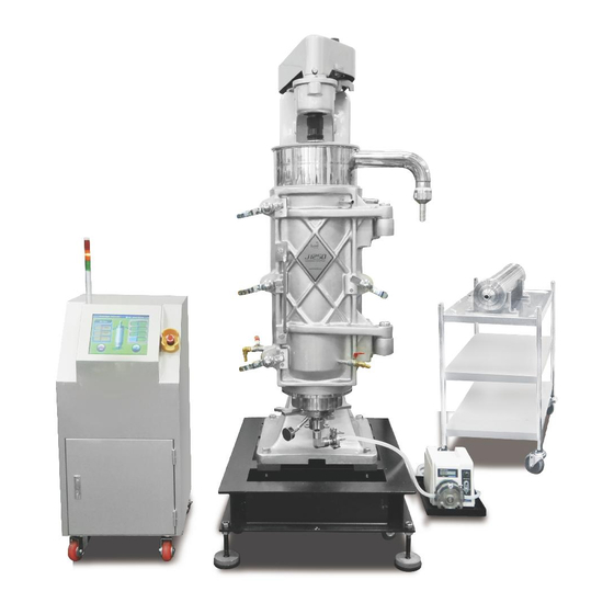
Page 5: Appearance -2
2. Appearance Front View Side View Upper View info@ihanil.com / techsupport@ihanil.com ㅣ 2... -
Page 6: Structure -3
3. Structure 3 ㅣinfo@ihanil.com / techsupport@ihanil.com... -
Page 7: Installation -4
The device should be installed on hard and flat place where anchor volts should be installed. <INSTALLATION> For the installation, please contact technical staff and get assistance from Hanil technical staffs. For balancing, put a level on the top of the bearing pulley and check the balance. The space between main body and wall should be at least 60cm and empty the front space. - Page 8 4. Installation <Piping> 1. Please use flexible tube on the feed pipe and please don’t use fixed type. 2. Please collect samples in cushion tank when the samples to be transferred to other tank or transfer through other pipes. This is for preventing the spouting. 3.
-
Page 9: Precautions -6
5. Precautions Because the J1250 spinning in high speed, to prevent any accident, please read following instruction very carefully. 1. Please check all the parts very carefully before operation. Especially, check the system very carefully after others’ usage. 2. Please remove any other items like towel or clothing that can be sucked into the machine. - Page 10 5. Precautions 6. Pay particular attention to the handling of the bowls and ensure that the threads are not scratched. 7. Please use only plastic hammer for assembly or disassembly and don’t use metal hammers. 7 ㅣinfo@ihanil.com / techsupport@ihanil.com...
-
Page 11: Lcd Display Operation -8
LCD Display Operation Operation [Set Value] • RPM/RCF: Set RPM or RCF • Time: Set operating time. Up to 99 hr 59 min 59 sec or Continuous • PROG: Save or recall a program • PUMP1/2: Each pump can be controlled and the pump is activated after the set rpm has been reached. - Page 12 LCD Display Operation After entering the setting value, touch the Run button. ▶ ▶ Level Sensor(optional): It is used to prevent overflow of the sample. A beep sounds when 80% of the used sample container reaches. The pump stops when it reaches 90% 9 ㅣinfo@ihanil.com / techsupport@ihanil.com...
- Page 13 Data on the Inverter and Diaphragm pump Specification Fixed No. Description Data A1-01 Access level B1-01 Currency selection B1-02 Operating type selection B2-02 DC control currency B2-04 DC control time for the stopping C1-01 Acceleration time C1-02 Deceleration time E1-01 Input voltage setting E1-04 Max.
-
Page 14: Data On The Inverter And Diaphragm Pump -10
Data on the Inverter and Diaphragm pump The counterplan for the problems Signal Description Cause Counterplan Excess Motor Increase the current overload accel (C1-01), and decal time (C1-02). Excess Short Increase the voltage deceleration deceleration time time (C1-02) High Use power voltage fluctuation transformer... - Page 15 Data on the Inverter and Diaphragm pump J-1250 Inverter Data Inverter Set Data(RPM) 2320 10,000 11,000 2550 2780 12,000 3010 13,000 3250 14,000 3480 15,000 16,000 3710 Gear Ratio : 1/4.32(4.44) <Inverter RPM setting> Press “ENTER” Select parameters using arrow keys Setting all the parameters ...
- Page 16 Data on the Inverter and Diaphragm pump <J1250 Control Input> 1. Touch the Set Value 2. Input 00:02:26 on the RPM Calibration UP and press Enter 3. Input 00:03:41 on the RPM Calibration Down and press Enter 4. Input 15000 on the RPM and press Enter 5.
- Page 17 Data on the Inverter and Diaphragm pump Touch ∴ and you can check the final input data Debug Window Program. RPMupcount Program. RPMdowncount Program. Motor Percent 4.32 Program. Rotor Radius 6.2814 Inverter RPM 15000 Inverter Input RPM 3472 Number RPM Set 15000 Touch X after checking the above table and then start operating.
- Page 18 Data on the Inverter and Diaphragm pump <P/G Change when particular operating> 1. In the input details of INVERTER SETTING 2. No. 08 : Change b1-01=2 to b1-01=0 3. No. 10 : Change b1-02=2 to b1-02=0 4. No. 76 : Touch DATA/ENTER key Example) In case the RPM is 15,000, press △, ▽, ▷...
- Page 19 8. Assembly and Operation Assembly 1. Install the Drag Assembly using hammer (Except part No. 38, 39 and 40) 2. Install the bowl into the drag hole located in frame 3. Install the sample collector. 4. Close the front door and lock using the hammer. 5.
- Page 20 8. Assembly and Operation Operation 1. After assembly, install the belt and adjust the tension on the Tension pulley and spin the Motor Pulley by hand to check. 2. In the beginning, there is some vibration but as speed increases, it becomes more stable (reaching 15,000 rpm/min in 1 minute).
- Page 21 Drag Structure The figure shows the cross section of the drag assembly. This part is supporting the bowl bottom and works as the sample inlets. It is maintained the locations by drag spring and 6 of the bullet catches. The nozzle is tightened by the hand nut Disassembly 1.
- Page 22 Drag Assembly Follow reverse order on disassembly. Please make sure grease from but bushing hole by twisting the grease cup. Caution 1. The bowl can be vibrates when the drag spring tension got weakened. Please replace it. 2. The bowl also can be vibrate when there is unbalance on the bullet catch tension. Please also replace it.
- Page 23 Drag Drag Assembly Drawing & Parts info@ihanil.com / techsupport@ihanil.com ㅣ20...
- Page 24 Trouble Shootings Damages on the belt damage 1. Is there any damage on the bearing pulley, Idler pulley, or motor pulley? If so, please make smooth using the emery paper. 2. The belt doesn’t work on the upper or downer regions on the pulley? If so, adjust the location of the Idler arm so that it spins in correct position on the Pulley.
- Page 25 8. Is the neck of the bowl upper region is not crooked? Please contact technical staffs in Hanil. 9. If there is abrasion on the bowl shell or bowl bottom, please contact technical staffs in Hanil.
- Page 26 Trouble Shootings Cut on the bowl seal 1. Is there any cut on the bowl bottom gasket or any scratch on the gasket contact regions? Please remind during bowl bottom disassembly. Problem on feeding 1. Is there any blockage on the feed nozzle? 2.
- Page 27 Trouble Shootings 3. Is there any abrasion on the bearing spacer? If the sleeve nut is not tightened properly, then the spacer can be abrasion. The height of new one is 16mm. Damages on the rubber coupling 1. Is there any damage on the pin of the pulley cap? 2.
- Page 28 Trouble Shootings 1) Bearing pulley The adjustment of the location of the belt for the bearing pulley depends on the location (up and down) of the tension pulley. 2) Motor pulley The adjustment of the location of the belt for the motor pulley depends on the location of the idler elbow (left and right).
- Page 29 MEMO...
- Page 30 Hanil Scientific Inc. 16 Arayukro, Gimpo 10136, Rep. of Korea Tech Support +82-2-3452-8966 l techsupport@ihanil.com www.ihanil.com...
Need help?
Do you have a question about the J1250 and is the answer not in the manual?
Questions and answers