
Related Manuals for IBM WebSphere DataPower 7198


Summary of Contents for IBM WebSphere DataPower 7198
- Page 1 WebSphere DataPower Type 7198 and 7199 Third Edition Installation and User's Guide...
- Page 3 WebSphere DataPower Type 7198 and 7199 Third Edition Installation and User's Guide...
- Page 4 Before using this information and the product it supports, read the information in “Notices” on page 63. Third Edition (September 2011) This edition applies to IBM WebSphere DataPower SOA Appliances Type 7198 and 7199 until otherwise indicated in new editions.
-
Page 5: Table Of Contents
Typeface conventions . xvii Chapter 6. Troubleshooting your Chapter 1. Introducing the IBM appliance ... . . 37 DataPower appliance ..1 Troubleshooting workflow . - Page 6 Electronic emission notices . . 63 Japanese Voluntary Control Council for Federal Communications Commission (FCC) Interference (VCCI) statement . . 65 statement . . 63 Taiwanese Class A warning statement . 65 Industry Canada Compliance Statement . . 64 Chinese Class A warning statement . .
-
Page 7: Safety
Avant d'installer ce produit, lisez les consignes de sécurité. German Vor der Installation dieses Produkts die Sicherheitshinweise lesen. Greek Hebrew Hungarian Italian Prima di installare questo prodotto, leggere le Informazioni sulla Sicurezza. Japanese Korean Macedonian © Copyright IBM Corp. 2011... -
Page 8: Guidelines For Servicing Electrical Equipment
Norwegian Les sikkerhetsinformasjonen (Safety Information) før du installerer dette produktet. Polish Portuguese Antes de instalar este produto, leia as Informações sobre Segurança. Russian Slovak Slovenian Pred namestitvijo tega proizvoda preberite Varnostne informacije. Spanish Antes de instalar este producto, lea la información seguridad. Swedish Läs säkerhetsinformationen innan du installerar den här produkten. -
Page 9: Inspecting For Unsafe Conditions
Use good judgment to identify potential unsafe conditions that might be caused by attachment of non-IBM features or options that are not addressed in this section. If you identify an unsafe condition, you must determine how serious the hazard is and whether you must correct the problem before you work on the product. -
Page 10: Safety Statements
However, the IBM Systems: Safety Notices document provides the complete list of all the safety notices for IBM Systems Software. You can access the IBM Systems: Safety Notices document on the IBM WebSphere DataPower SOA Appliances: Resource Kit CD. -
Page 11: Danger Notices
Electrical voltage and current from power, telephone, and communication cables are hazardous. To avoid a shock hazard: v Connect power to this unit only with the IBM provided power cord. Do not use the IBM provided power cord for any other product. -
Page 12: Caution Notices
Do not repair or disassemble. Exchange only with the IBM-approved part. Recycle or discard the battery as instructed by local regulations. In the United States, IBM has a process for the collection of this battery. For information, call 1-800-426-4333. Have the IBM part number for the battery unit available when you call. - Page 13 Use the following general safety information for all rack-mounted devices. DANGER Observe the following precautions when working on or around your IT rack system: v Heavy equipment — personal injury or equipment damage might result if mishandled. v Always lower the leveling pads on the rack cabinet. v Always install stabilizer brackets on the rack cabinet.
- Page 14 CAUTION: Removing components from the upper positions in the rack cabinet improves rack stability during relocation. Follow these general guidelines whenever you relocate a populated rack cabinet within a room or building: v Reduce the weight of the rack cabinet by removing equipment starting at the top of the rack cabinet.
-
Page 15: Labels
Labels DANGER Hazardous voltage, current, or energy levels are present inside any component that has this label attached. Do not open any cover or barrier that contains this label. (L001) DANGER Rack-mounted devices are not to be used as shelves or work spaces. (L002) DANGER Multiple power cords. - Page 16 Installation and User's Guide...
-
Page 17: Preface
Who should read this guide This guide is intended for personnel who will install, configure, diagnose, and service the IBM WebSphere DataPower SOA Appliances Type 7198 and 7199. The tasks addressed in this guide include: v Installing rails in the rack frame for the appliance. -
Page 18: The Resource Kit Cd
Warranty information The IBM Statement of Limited Warranty for this product is provided on the IBM WebSphere DataPower SOA Appliances: Resource Kit CD that comes with this product. The statement is also available in 29 languages from the IBM web site at http://www.ibm.com/servers/support/machine_warranties/ without the... -
Page 19: Typeface Conventions
The following notices and statements are used in this document: Note This section provides important tips, guidance, or advice. Best Practice This section provides guidance about best practices. Attention This section indicates potential damage to programs, devices, or data. An attention notice is placed just before the instruction or situation in which damage might occur. - Page 20 xviii Installation and User's Guide...
-
Page 21: Chapter 1. Introducing The Ibm Datapower Appliance
Chapter 1. Introducing the IBM DataPower appliance IBM WebSphere DataPower appliances are network devices that communicate with other nodes on an IP network. DataPower appliances are easy-to-deploy network devices that help simplify, accelerate, and secure your XML and Web services. -
Page 22: Features
Table 1. Appliance specifications (continued) Power usage 10 A for 110 V AC 5 A for 220 V AC v The Type 7198 appliance contains two 650-watt power modules v The Type 7199 appliance contains two 720-watt power modules Both power supply modules must be connected to the same power source to prevent a difference in ground voltage between the two power modules. -
Page 23: Identifying Components
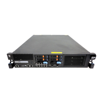
The Ethernet modules and the hard disk drive modules are installed from the front of the appliances, as discussed in Chapter 7, “Removing or replacing the appliance or parts,” on page 41. Figure 1. Type 7198 front view Chapter 1. Introducing the IBM DataPower appliance... - Page 24 Figure 2. Type 7199 front view The labels in Figure 1 on page 3 and Figure 2 correspond to the following components on the front of the appliances: Console connector USB port LCD module Hard disk drive module 2 Hard disk drive module 0 Hard disk drive module 3 Hard disk drive module 1 Fault LED...
- Page 25 Note: When you press the power button to turn off the appliance, there is still electrical current flowing to the device. To disconnect all electricity to the appliance, unplug all power cords. Chapter 1. Introducing the IBM DataPower appliance...
- Page 26 Network connectors The front panel has two LAN management Ethernet ports and two Ethernet modules. See “Ethernet network configuration” on page 9 for a description of the Ethernet numbering convention. LAN management Ethernet ports: The MGT0 and MGT1 management Ethernet ports provide connection to the LAN.
-
Page 27: Rear View
Figure 6 on page 8 shows the components on the rear of Type 7199 appliances. The fan modules and power modules are installed from the rear of the appliance, as discussed in Chapter 7, “Removing or replacing the appliance or parts,” on page Chapter 1. Introducing the IBM DataPower appliance... - Page 28 Figure 5. Type 7198 rear view Figure 6. Type 7199 rear view The labels in Figure 5 and Figure 6 correspond to the following components on the rear of the appliance: Fan module 1 LED for fan module 1 Fan module 2 LED for fan module 2 Fan module 3 LED for fan module 3...
-
Page 29: Ethernet Network Configuration
The left Ethernet module has eight 1 Gigabit Ethernet ports, which are RJ45 connectors. v The right Ethernet module has two 10 Gigabit Ethernet ports, which are small form-factor pluggable (SFP+) transceivers. Chapter 1. Introducing the IBM DataPower appliance... - Page 30 The appliance has ten Ethernet connections. The Ethernet interface names are ETH10 through ETH17, ETH20, and ETH21 (as shown in Figure 8). Figure 8. Type 7199 8 by 2 Ethernet connection Installation and User's Guide...
-
Page 31: Chapter 2. Preparing For Installation
There must be at least 30 in. (76.20 cm) of free space behind the rack frame to remove replaceable parts. v The ambient temperature in the operating environment and within the rack should not exceed 95° F (35° C). © Copyright IBM Corp. 2011... - Page 32 Electrical voltage and current from power, telephone, and communication cables are hazardous. To avoid a shock hazard: v Connect power to this unit only with the IBM provided power cord. Do not use the IBM provided power cord for any other product.
- Page 33 DANGER Observe the following precautions when working on or around your IT rack system: v Heavy equipment — personal injury or equipment damage might result if mishandled. v Always lower the leveling pads on the rack cabinet. v Always install stabilizer brackets on the rack cabinet. v To avoid hazardous conditions due to uneven mechanical loading, always install the heaviest devices in the bottom of the rack cabinet.
-
Page 34: Tool Requirements
CAUTION: Removing components from the upper positions in the rack cabinet improves rack stability during relocation. Follow these general guidelines whenever you relocate a populated rack cabinet within a room or building: v Reduce the weight of the rack cabinet by removing equipment starting at the top of the rack cabinet. - Page 35 To fully set up and test the appliance in your network, use the following high-level processes: 1. Install the appliance in a rack: a. Install the rails in the rack. b. Secure the appliance in the rack. c. Connect the appliance to an AC source. d.
- Page 36 Installation and User's Guide...
-
Page 37: Chapter 3. Installing The Appliance In A Rack
Select one of the slide rails and push up on the front moveable tab 1 ; then, pull out the front latch 2 . c. If a thumbscrew is installed in the slide rail 3 , remove the thumbscrew. © Copyright IBM Corp. 2011... - Page 38 Figure 9. View of the slide rails 2. Install the rear end of the slide rails, as shown in Figure 10: a. From the front of the rack, line up the three pins on the rear of the slide rail with the three holes in the selected U on the rear of the rack.
-
Page 39: Installing The Appliance On The Slide Rails
c. Repeat steps 1 through 3 to install the other rail into the rack. Make sure that each front latch is fully engaged. Rack Front Figure 11. Install the front end of the slide rails 4. Secure the appliance slide rails in the rack, as shown in Figure 12: a. - Page 40 > 18 kg (39.7 lb) To install the appliance on the slide rails, complete the following steps as shown in Figure 13. 1. Pull the slide rail forward 1 . 2. Use two people to carefully lift the appliance 2 and tilt it into position over the slide rails so that the rear nail heads 3 on the appliance line up with the rear slots 4 on the slide rails.
-
Page 41: Connecting The Appliance To An Ac Power Source
Figure 14. Slide the appliance into the rack Connecting the appliance to an AC power source Use the provided power cords to connect both power supply modules to an AC power source. You must connect each power supply modules. Otherwise, the unconnected module is considered to be in a failed state. - Page 42 – Optical interface specifications per IEEE 802.3ae 10GBASE-SR – Mechanical specifications per SFF Committee SFF 8432 Improved Pluggable Formfactor IPF – Class 1 Eye safe per requirements of IEC 60825-1 / CDRH v Long-reach (10 km) SFP+ modules with LC connector (single-mode yellow fiber) –...
-
Page 43: Chapter 4. Setting Up The Initial Firmware Configuration
Ethernet interfaces. v The IP addresses and ports for the Web Management and SSH services. The Web Management service is required to accept the license agreement. v Optional: The IP address and port for Telnet service. © Copyright IBM Corp. 2011... -
Page 44: Firmware Considerations
Best Practice: Use MGT0 or MGT1 Ethernet interface for system-wide management functions to handle network traffic for incoming SNMP, SSH, and Web Management (WebGUI) functions on your intranet. If you have a serial over LAN connection, it must be configured on MGT0. The remaining Ethernet interfaces can handle data traffic and logging functions to and from the various DataPower services. -
Page 45: Consideration For The License Agreement
Attention: Do not forget or misplace the password for the admin account. If you forget or misplace this password, security best practice recommends that you return the appliance to IBM Support to reset this password. However, if another user account can log in and has the appropriate access permission, that user can reset the password for the admin account. - Page 46 If you use the USB serial console cable and your PC does not recognize the cable, you might need to install the device driver. The drivers are on the IBM WebSphere DataPower SOA Appliances: Resource Kit CD in an archive file.
-
Page 47: Procedure 2 Of 4: Initializing The Appliance
Next step: Initialize the appliance by accepting the license, changing the password for the admin account, and interactively defining the base configuration. See “Procedure 2 of 4: Initializing the appliance.” Procedure 2 of 4: Initializing the appliance Before you begin: Connect the serial cable to the appliance. “Procedure 1 of 4: Connecting the serial cable to the appliance”... -
Page 48: Procedure 3 Of 4: Creating Users Who Can Reset Passwords
The screen shows information specific to your appliance. Welcome to DataPower XI52 console configuration. Copyright IBM Corporation 1999-2011 Version: XI52.4.0.2.0 build 123456 on 2011/06/13 12:32:13 Serial number: 68A00000 You must read and agree to the terms of the license agreement using the WebGUI. -
Page 49: Procedure 4 Of 4: Accepting The License Agreement
4. Click Login. The WebGUI displays the license agreement. v Click I agree to accept the terms of the license agreement and non IBM-terms. The appliance reloads the firmware. In a few minutes, you can log in again after the appliance restarts. - Page 50 Installation and User's Guide...
-
Page 51: Chapter 5. Diagnosing Your Appliance
The amber fault LED is illuminated when the appliance detects a problem condition with hardware components. The blue locate LED is illuminated when an administrator is trying locate and identify a certain appliance in the rack. The locate LED is activated by © Copyright IBM Corp. 2011... -
Page 52: Leds On The Rear Panel
the DataPower firmware, and the locate LED is turned of when deactivated by the DataPower firmware. For information about controlling this LED, see “LEDs” on page 5. The green power LED indicates the status of the power source for the appliance. -
Page 53: Testing The Hardware From The Command Line
Figure 18. LEDs on the rear on the Type 7199 appliance The rear of the appliance has the following LEDs: A, B, and C The LEDs for a fan module indicate the following status: v If the amber LED is illuminated, there is a problem with the module. v If the LED is not illuminated, the module is operating normally. -
Page 54: Using The Diagnostic Self-Test
The Type 7198 and 7199 appliance provides a boot-time diagnostic self-test to help you test hardware components. Note: Only use the diagnostic self-test when directed by IBM Support to help confirm a potential hardware problem with the appliance. To initialize the diagnostic self-test: 1. -
Page 55: Viewing Status Providers For Sensors
DataPower Hardware Diagnostics Tool Version 1.0 (C) Copyright 2011 - IBM Corporation Main Menu: 1. Inventory 2. BMC/Sensors 3. Network 4. Memory 5. Disks 0. Exit Diagnostics Select action> 5. To select a test to run, enter its number at the Select action prompt. - Page 56 RAID battery backup status Monitors the battery backup unit on the RAID controller. From the WebGUI, click STATUS → System → RAID Battery Backup Status. From the command line, enter show raid-battery-backup. Other sensors Provides truth values for the intrusion switch, power supply modules, batteries, and the hard disks.
-
Page 57: Chapter 6. Troubleshooting Your Appliance
Troubleshooting workflow To help you troubleshoot the problem and determine whether you need to contact IBM Support for assistance or to order a replacement part, use the following workflow: 1. Did you receive a critical event through SNMP or SMTP notification? -
Page 58: Troubleshooting Cru Parts
“Replacing a fan module” on page 49 to remove and reinsert the module. If you believe that the module needs to be replaced, contact IBM Support. For information about contacting IBM Support and what information you need to gather before contacting IBM Support, see“Using the diagnostic self-test”... -
Page 59: Troubleshooting The Hard Disk Drive Module
If the module does not have AC power, ensure that the power cords are connected correctly to the power supply and to a working AC power outlet. If you believe that the module needs to be replaced, contact IBM Support. For information about contacting IBM Support and what information you need to gather before contacting IBM Support, see“Getting help and technical assistance,”... - Page 60 <ESC> within 7 seconds for boot options... 5. Wait for a few minutes for the appliance to boot. 6. If the appliance demonstrates any of the following symptoms, contact IBM Support: v The screen does not display DPOS boot - press <ESC> within 7 seconds for boot options...
-
Page 61: Chapter 7. Removing Or Replacing The Appliance Or Parts
The appliance includes two of three types of replacement parts: Tier 1 customer replaceable unit (CRU) and field replaceable unit (FRU). However, replacement parts for other IBM machine types can be any of the following types: Tier 1 CRU Replacement of a Tier 1 CRU is your responsibility. If an IBM representative installs a Tier 1 CRU at your request, you will be charged for the installation. -
Page 62: Handling Static-Sensitive Devices
If you are instructed to return an appliance or component, follow all packaging instructions and use any of the packaging materials that is provided for shipping. Note: You may be charged for the replacement appliance or part if IBM does not receive the defective appliance or part within a reasonable timeframe. -
Page 63: Cru Parts Listing
For information about obtaining service or assistance, see “Getting help and technical assistance,” on page 61. CRU parts listing The Ethernet modules, hard disk drive modules, fan modules, and power supply modules are CRU parts. Figure 19 shows the CRU parts on the front and rear of the Type 7198 appliance. -
Page 64: 7199 Parts Listing
7199 parts listing The Type 7199 appliance includes Tier 1 CRU parts and FRU parts. For information about the terms of warranty, see the IBM Statement of Limited Warranty document on the IBM WebSphere DataPower SOA Appliances: Resource Kit For information about obtaining service or assistance, see “Getting help and technical assistance,”... - Page 65 Figure 20. 7199 CRU parts numbers Table 8 lists the part numbers and their corresponding descriptions. Table 8. Part numbers for the Type 7199 appliance Tier 1 CRU part Index Description number Hard disk drive modules 46N5587 Ethernet module eight port 1 gigabit connector 97Y0446 Ethernet module two port 10 gigabit connector 97Y0444...
-
Page 66: Fru Parts Listing
In the United States, you might need to purchase optional rack power cables for rack mounting needs. To maintain warranty or service contracts, you must use IBM parts for power cords and rack cables. Table 10. Power cords and cables... -
Page 67: Turning Off The Appliance
Electrical voltage and current from power, telephone, and communication cables are hazardous. To avoid a shock hazard: v Connect power to this unit only with the IBM provided power cord. Do not use the IBM provided power cord for any other product. -
Page 68: Removing And Replacing Cru Parts
Before proceeding, verify that the power LED is not illuminated. Removing and replacing CRU parts Replacement of Tier 1 CRU parts is your responsibility. If an IBM representative installs a Tier 1 CRU part at your request, you will be charged for the installation. -
Page 69: Replacing A Fan Module
Electrical voltage and current from power, telephone, and communication cables are hazardous. To avoid a shock hazard: v Connect power to this unit only with the IBM provided power cord. Do not use the IBM provided power cord for any other product. - Page 70 Best Practice: Turn off the appliance as soon as possible to avoid overheating. The remaining fans might not be able to maintain the appropriate environmental temperature. To replace a failed fan module: 1. If the appliance is not turned off, perform a graceful shutdown by pressing the power button on the front of the chassis.
-
Page 71: Replacing A Power Supply Module
The LED for the fan module is not illuminated. v The fault LED is not illuminated. After verifying that the replacement module is working, return the part to IBM. For details, see “Returning an appliance or part” on page 42. - Page 72 The power supply LED is illuminated in green. v The fault LED is not illuminated. After verifying that the replacement module is working, return the part to IBM. For details, see “Returning an appliance or part” on page 42.
-
Page 73: Replacing A Hard Disk Drive Module
Electrical voltage and current from power, telephone, and communication cables are hazardous. To avoid a shock hazard: v Connect power to this unit only with the IBM provided power cord. Do not use the IBM provided power cord for any other product. - Page 74 Figure 25. Controls and LEDs on the hard disk drive module Release button. Press to open the lever to remove the module. Locking control. To unlock, move left. To lock, move right. Activity LED Fault LED. Nonfunctional on Type 7198 appliances. To replace the hard disk drive module: 1.
- Page 75 The fault LED light on the front of the chassis is not illuminated. After verifying that the replacement module is working, return the part to IBM. For details, see “Returning an appliance or part” on page 42. Chapter 7. Removing or replacing the appliance or parts...
-
Page 76: Replacing An Ethernet Module
Electrical voltage and current from power, telephone, and communication cables are hazardous. To avoid a shock hazard: v Connect power to this unit only with the IBM provided power cord. Do not use the IBM provided power cord for any other product. - Page 77 – From the show interface command. – From the WebGUI: click STATUS → IP Network → Ethernet Interfaces. You must turn off the appliance before replacing the Ethernet module. To replace an Ethernet module: v If the appliance is not turned off, perform a graceful shutdown by pressing the power button on the front of the chassis.
-
Page 78: Removing An Sfp Transceiver
If you are replacing a failed Ethernet module, verify that the replacement module is working and return the failed part to IBM. See “Returning an appliance or part” on page 42 for details on returning parts to IBM. Removing an SFP transceiver... -
Page 79: Removing The Appliance From The Rack
v Unplug all power cords. v Pull downward on the blue latch on the front of the transceiver, as shown in Figure 28. v Pull the transceiver out by pulling forward the blue latch. Figure 28. Removing the SFP transceiver Removing the appliance from the rack Generally, after installing the appliance in the rack, you need to remove it only to move it to another position in the rack. - Page 80 Lift point Lift point Figure 29. Unlatching and rotating the front of the appliance 2. Lift the appliance off of the slide rails, as shown in Figure 30. a. After the front nailheads clear the latches, lift up on the rear 1 of the appliance to level the appliance.
-
Page 81: Appendix. Getting Help And Technical Assistance
You have the appliance serial number. v You have the customer number that was used to purchase the appliance. You can submit a software problem report to IBM for a DataPower appliance in the following ways: v Use the service request (SR) problem submission web page. You will need to sign in with your IBM user ID and password. - Page 82 Contact IBM via the telephone. See the directory of worldwide contacts in the IBM Software Support Handbook (http://www14.software.ibm.com/webapp/ set2/sas/f/handbook/contacts.html) for the appropriate support telephone number. For additional information on contacting IBM support, see technote 7012462 (http://www.ibm.com/support/docview.wss?uid=swg27012462). Installation and User's Guide...
-
Page 83: Notices
Consult your local IBM representative for information about the products and services currently available in your area. Any reference to an IBM product, program, or service is not intended to state or imply that only that IBM product, program, or service may be used. Any functionally equivalent product, program, or service that does not infringe any IBM intellectual property right may be used instead. -
Page 84: Industry Canada Compliance Statement
Properly shielded and grounded cables and connectors must be used in order to meet FCC emission limits. IBM is not responsible for any radio or television interference caused by using other than recommended cables and connectors or by unauthorized changes or modifications to this equipment. -
Page 85: Japanese Voluntary Control Council For Interference (Vcci) Statement
Japanese Voluntary Control Council for Interference (VCCI) statement The following is a summary of the VCCI Japanese statement in the box above. This is a Class A product based on the standard of the Voluntary Control Council for Interference by Information Technology Equipment (VCCI). If this equipment is used in a domestic environment, radio disturbance may arise. -
Page 86: Russian Class A Warning Statement
( ), these symbols indicate U.S. registered or common law trademarks owned by IBM at the time this information was published. Such trademarks may also be registered or common law trademarks in other countries. A current list of IBM trademarks is available on the Web at “Copyright and trademark information”... - Page 88 Part Number: 97Y0541 Printed in USA (1P) P/N: 97Y0541...
Need help?
Do you have a question about the WebSphere DataPower 7198 and is the answer not in the manual?
Questions and answers