Table of Contents
Advertisement
Quick Links
INSTALLATION AND OPERATION MANUAL
Stratford
(OB04003 Model)
250, rue de Copenhague, St-Augustin-de-Desmaures (Québec) Canada G3A 2H3
customer service: 418-908-8002
This manual is available for free download on the manufacturer's web site. It is a copyrighted
document. Re-sale is strictly prohibited. The manufacturer may update this manual from
time to time and cannot be responsible for problems, injuries, or damages arising out of the
use of information contained in any manual obtained from unauthorized sources.
Printed in Canada
www.osburn-mfg.com
Stove Builder International Inc.
E-mail: tech@sbi-international.com
READ AND KEEP THIS MANUAL FOR REFERENCE
US ENVIRONMENTAL PROTECTION
AGENCY PHASE II CERTIFIED WOOD
FIREPLACE
Listed to standards ULC-S610 and UL 127
by an accredited laboratory
45919A
30-07-2018
Advertisement
Table of Contents

Related Manuals for Osburn OB04003


Summary of Contents for Osburn OB04003
- Page 1 INSTALLATION AND OPERATION MANUAL Stratford (OB04003 Model) US ENVIRONMENTAL PROTECTION AGENCY PHASE II CERTIFIED WOOD FIREPLACE Listed to standards ULC-S610 and UL 127 by an accredited laboratory www.osburn-mfg.com Stove Builder International Inc. 250, rue de Copenhague, St-Augustin-de-Desmaures (Québec) Canada G3A 2H3 customer service: 418-908-8002 E-mail: tech@sbi-international.com...
- Page 2 Stratford Fireplace Installation and Operation Manual THANK YOU FOR CHOOSING THIS OSBURN WOOD FIREPLACE As one of North America’s largest and most respected wood stove and fireplace manufacturers, Stove Builder International takes pride in the quality and performance of all its products. We want to help you get maximum satisfaction as you use this product.
-
Page 3: Table Of Contents
Table of content PART A - OPERATION AND MAINTENANCE ....... 6 1 Safety Information ..............6 Summary of Operation and Maintenance Cautions and Warnings ......6 2 General Information on Stratford (OB04003) ......8 Appliance Performance ..................8 General Features ....................9 Zone Heating and How to Make it Work for You .......... - Page 4 Stratford Fireplace Installation and Operation Manual 5.1.1 Plated Finish Maintenance ................24 5.1.2 Glass Door Cleaning ..................24 5.1.3 Door Adjustment ....................25 5.1.4 Door Alignment ....................26 5.1.5 Replacing the Door Gasket ................27 5.1.6 Replacing the Glass Gasket and/or the Glass ........... 28 5.1.7 Cleaning and Painting the Fireplace ..............
- Page 5 To receive full warranty coverage, you will need to show evidence of the date you purchased your fireplace. Keep your sales invoice. We also recommend that you register your warranty online at: https://www.osburn-mfg.com/en/warranty/warranty-registration/ Registering your warranty online will help us to quickly track the information we need about your fireplace.
-
Page 6: Part A - Operation And Maintenance
Stratford Fireplace Installation and Operation Manual PART A - OPERATION AND MAINTENANCE Please see Part B for installation instructions. 1 SAFETY INFORMATION 1.1 SUMMARY OF OPERATION AND MAINTENANCE CAUTIONS AND WARNINGS • HOT WHILE IN OPERATION, KEEP CHILDREN, CLOTHING AND FURNITURE AWAY. CONTACT MAY CAUSE SKIN BURNS. - Page 7 Stratford Fireplace Installation and Operation Manual SOME JURISDICTIONS IN THE USA REQUIRE A SUPPLY OF OUTDOOR COMBUSTION AIR FOR THE FIREPLACE. IN • CANADA, AN OUTDOOR AIR SUPPLY IS NOT REQUIRED, IF A CARBON MONOXIDE (CO) DETECTOR/ALARM IS LOCATED IN THE ROOM IN WHICH THE FIREPLACE IS INSTALLED. THE CO DETECTOR WILL PROVIDE WARNING IF FOR ANY REASON THE WOOD FIREPLACE FAILS TO FUNCTION CORRECTLY.
-
Page 8: General Information On Stratford (Ob04003)
Stratford Fireplace Installation and Operation Manual GENERAL INFORMATION ON STRATFORD (OB04003) 2.1 APPLIANCE PERFORMANCE Fuel type Dry cordwood Recommended heating area 750 to 2,100 ft (70 to 195 m Firebox volume 2.5 ft (0.071 m Maximum burn time Maximum heat output (dry cordwood) 75,000 BTU/h (22.0 kW) -
Page 9: General Features
Stratford Fireplace Installation and Operation Manual 2.2 GENERAL FEATURES Maximum log length 21 in (533 mm) east-west* Flue outlet diameter 6 in (150 mm) Chimney diameter 6 in (150 mm) CAN/ULC S604, UL 103 (1700 °F) Type of chimney CAN/ULC S629, UL 103 HT (2100 °F) Baffle material C-Cast Approved for alcove installation... - Page 10 Stratford Fireplace Installation and Operation Manual 10 __________________________________________________________________________...
- Page 11 Stratford Fireplace Installation and Operation Manual __________________________________________________________________________ 11...
- Page 12 Stratford Fireplace Installation and Operation Manual 12 __________________________________________________________________________...
-
Page 13: Zone Heating And How To Make It Work For You
Stratford Fireplace Installation and Operation Manual 2.3 ZONE HEATING AND HOW TO MAKE IT WORK FOR YOU Your new Stratford wood fireplace is a space heater, which means it is intended to heat the area it is installed in, as well as spaces that connect to that area, although to a lower temperature. This is called zone heating and it is an increasingly popular way to heat homes or spaces within homes. -
Page 14: Fuel
Stratford Fireplace Installation and Operation Manual The paint coating on your fireplace is very thin. Its VOC content (Volatile Organic Compounds) is very low. VOCs can be responsible for smog, so all the paint used during the manufacturing process meets the latest air quality requirements regarding VOC reduction or elimination. -
Page 15: Log Length
Stratford Fireplace Installation and Operation Manual Homeowners with access to both hardwood and softwood fuel sometimes use both types for different purposes. For example, softer woods make good fuel for relatively mild weather in spring and fall because they light quickly and produce less heat Softwoods are not as dense as hardwoods, so a given volume of wood contains less energy. -
Page 16: Judging Firewood Moisture Content
Stratford Fireplace Installation and Operation Manual Here are some things to consider in estimating drying time: Firewood takes a long time to dry; • Firewood bought from a dealer is rarely dry enough to • burn, so it is advisable to buy the wood in spring and dry it yourself;... -
Page 17: Manufactured Logs
Stratford Fireplace Installation and Operation Manual 3.3 MANUFACTURED LOGS Do not burn manufactured logs made of wax impregnated sawdust or logs with any chemical additives. Manufactured logs made of 100% compressed sawdust can be burned, but be careful burning too much of these logs at the same time. -
Page 18: Operating Your Fireplace
Stratford Fireplace Installation and Operation Manual 4 OPERATING YOUR FIREPLACE 4.1 THE USE OF A FIRESCREEN This fireplace has been tested for use with an open door in conjunction with a firescreen (AC01560, sold separately). Make sure the firescreen is properly secured on the fireplace to avoid any risk of sparks damaging your flooring. -
Page 19: Conventional Fire Starting
Stratford Fireplace Installation and Operation Manual 4.3.1 CONVENTIONAL FIRE STARTING The conventional way to build a wood fire is to bunch up 5 to 10 sheets of plain newspaper and place them in the firebox. Next, place 10 or so pieces of fine kindling on the newspaper. -
Page 20: Using Fire Starters
Stratford Fireplace Installation and Operation Manual 4.3.4 USING FIRE STARTERS Many people like to use commercial fire starters instead of newspaper. Some of these starters are made of sawdust and wax and others are specialized flammable solid chemicals. Follow the package directions for use. -
Page 21: Raking Charcoal
Stratford Fireplace Installation and Operation Manual NEVER STORE ASHES INDOORS OR IN A NON-METALIC CONTAINER OR ON A WOODEN DECK. 4.4.3 RAKING CHARCOAL Rekindle the fire when you notice that the room temperature has fallen. You will find most of the remaining charcoal at the back of the firebox, furthest from the door. -
Page 22: Building Different Fires For Diverse Needs
Stratford Fireplace Installation and Operation Manual You will notice that as you reduce the air setting, the flames slow down. This is your indication that the fireplace is burning at its peak efficiency. If the flames get small and almost disappear when you turn down the air, you have turned down the air too early, or your firewood is wetter than it should be. - Page 23 Stratford Fireplace Installation and Operation Manual 4.4.6.3 High Output Fires for Cold Weather When the heat demand is high during cold weather, you’ll need a fire that burns steadily and brightly. This is the time to use larger pieces of hardwood fuel if you have it. Put the biggest pieces at the back of the firebox and place the rest of the pieces compactly.
-
Page 24: Maintaining Your Wood Heating System
Stratford Fireplace Installation and Operation Manual 5 MAINTAINING YOUR WOOD HEATING SYSTEM 5.1 FIREPLACE MAINTENANCE Your new fireplace will give many years of reliable service if you use and maintain it correctly. Some of the internal components of the firebox, such as firebricks, baffles and air tubes, will wear over time under intense heat. -
Page 25: Door Adjustment
Stratford Fireplace Installation and Operation Manual 5.1.3 DOOR ADJUSTMENT In order for your fireplace to burn at its best efficiency, the door must provide a perfect seal with the firebox. Therefore, the gasket should be inspected periodically to check for a good seal. The gasket seal may be improved with a simple latch mechanism adjustment. -
Page 26: Door Alignment
Stratford Fireplace Installation and Operation Manual 5.1.4 DOOR ALIGNMENT To align, open the fireplace’s doors and loosen the pressures screws located on the lower and upper hinges of each door using a 3/32" Allen key to free the adjustable hinge rods. Using a flat screwdriver, turn the adjustable hinge rods in the direction shown to adjust the doors. -
Page 27: Replacing The Door Gasket
Stratford Fireplace Installation and Operation Manual 5.1.5 REPLACING THE DOOR GASKET It is important to maintain the gaskets in good condition. After a year or more of use, the door gaskets will compress and become hard, which may allow air to leak past it. You can test the condition of the door gaskets by closing and latching the door on a strip of paper. -
Page 28: Replacing The Glass Gasket And/Or The Glass
Stratford Fireplace Installation and Operation Manual 5.1.6 REPLACING THE GLASS GASKET AND/OR THE GLASS It is a good idea to replace the glass gasket when the door gasket is replaced. The gasket is flat, adhesive-backed, woven fibreglass. Remove the glass retaining screws (A) and clips (B) then the metal frames (C) that hold the glass (D) to the door frame (E). -
Page 29: Cleaning And Painting The Fireplace
1400º F. If the glass breaks, it must be replaced with one having the same specification. Contact your OSBURN dealer to obtain a genuine replacement part. WARNING: TEMPERED GLASS OR ORDINARY GLASS WILL NOT WITHSTAND THE HIGH TEMPERATURES OF THE STRATFORD. -
Page 30: Cleaning The Chimney
Stratford Fireplace Installation and Operation Manual 5.2.3 CLEANING THE CHIMNEY Chimney cleaning can be a difficult and dangerous job. If you don’t have experience cleaning chimneys, you might want to hire a professional chimney sweep to clean and inspect the system for the first time. After having seen the cleaning process, you can decide if it is a job you would like to take on. -
Page 31: Chimney Fire
Stratford Fireplace Installation and Operation Manual 5.2.5 CHIMNEY FIRE Regular chimney maintenance and inspection can prevent chimney fires. If you have a chimney fire, follow these steps: 1. Close the fireplace door and the air intake controls; 2. Alert your family of the possible danger; 3. -
Page 32: Part B - Installation
Stratford Fireplace Installation and Operation Manual PART B – INSTALLATION Install the fireplace only as described in these instructions and using only components from the chimney manufacturers listed in table 2. Parts Required • Stratford Fireplace • Insulated chimney made by the manufacturers listed in table 2, with the corresponding specifications: −... -
Page 33: Regulations Covering Fireplace Installation
Stratford Fireplace Installation and Operation Manual REGULATIONS COVERING FIREPLACE INSTALLATION When installed and operated as described in these instructions, the Stratford wood fireplace is suitable for use in residential installations. The Stratford wood fireplace is not intended for installation in a bedroom of a mobile home. -
Page 34: Raised Base Installation Of More Than 4" (R Value For The Hearth Extension Not Required)
Stratford Fireplace Installation and Operation Manual Specifications. Next, measure the area occupied by the fireplace, note the floor construction and consult your local building code to determine if additional support is needed. 6.2.1 RAISED BASE INSTALLATION OF MORE THAN 4" (R VALUE FOR THE HEARTH EXTENSION NOT REQUIRED) The Stratford may be installed directly on the floor or on a raised combustible or non combustible base. -
Page 35: On The Floor Or On A Raised Base Of Less Than 4" Installation (R Value For The Hearth Extension Required)
Stratford Fireplace Installation and Operation Manual In the case where (F) would be equal to 4", it is suggested that the sheet metal between the base of the fireplace and floor be in one piece. 6.2.2 ON THE FLOOR OR ON A RAISED BASE OF LESS THAN 4" INSTALLATION (R VALUE FOR THE HEARTH EXTENSION REQUIRED) In the case where the fireplace is installed directly on the floor or on a raised base of less than 4", an R value for the hearth extension is required. -
Page 36: R Calculations
Stratford Fireplace Installation and Operation Manual A noncombustible floor protection with R value insulation equal to or greater than 1.00 must be installed in front of the unit. For more details see Section 6.2.2: Minimum Hearth Extension Requirements. The use of an R value is convenient when more than one material is going to be used in the hearth extension to cover the combustible surface. -
Page 37: Minimum Hearth Extension Requirements
Stratford Fireplace Installation and Operation Manual Thermal Characteristics of Common Floor Protection Materials* MATERIAL CONDUCTIVITY (k) RESISTANCE (R) PER INCH PER INCH THICKNESS ® Micore 0.39 2.54 Micore ® 0.49 2.06 Durock ® 1.92 0.52 Hardibacker ® 1.95 0.51 Hardibacker ®... -
Page 38: Framing, Facing, Mantel, And Combustible Shelf
Stratford Fireplace Installation and Operation Manual 6.2.5 FRAMING, FACING, MANTEL, AND COMBUSTIBLE SHELF 6.2.5.1 Framing The construction of the framing, facing, and mantel must be in accordance with the standards and the following illustrations: A. Frame the sides and back of the fireplace using 2" × 3" (5 cm x 8 cm) or heavier lumber. However, the front studs as well as headers on top of the fireplace must be of a depth no more than the depth of the top standoffs. - Page 39 Stratford Fireplace Installation and Operation Manual Wall finish behind the fireplace’s faceplate installation MEASUREMENTS CLEARANCES 37 7/8" (961 mm) 4 7/8" (124 mm) 24 3/4" (630 mm) 8" (203 mm) 1 1/2" (39 mm) MAX 5" (127 mm) 80" (2032 mm) *When drywall panels or any other finishing material inside the chase around the fireplace is to be used, add its thickness to the measurement.
- Page 40 Stratford Fireplace Installation and Operation Manual See Appendixes for fresh air intake kit (L) and forced air distribution kit (K) installation. Fresh air intake kit and forced air distribution kit installation LEGEND Combustible material allowed in this area Non-combustible material only in this area MINIMUM MEASUREMENTS MINIMUM MEASUREMENTS...
- Page 41 Stratford Fireplace Installation and Operation Manual CLEARANCES** 53 1/2" (1359 mm) 75 1/2" (1918 mm) *When drywall panels or any other finishing material inside the chase around the fireplace is to be used, add its thickness to the measurement. **Values M and N are minimum measurements. They may need to be increased to alloy installation of a fresh air intake kit or forced air distribution kit or depending on the finish material used.
- Page 42 Stratford Fireplace Installation and Operation Manual 6.2.5.2 Facing Non-combustible material such as brick, stone or ceramic tile may be in contact with the fireplace decorative frame. Note that if you ever needed to remove the decorative frame, it might be wise not to seal between the faceplate and finishing material.
- Page 43 Stratford Fireplace Installation and Operation Manual 6.2.5.3 Compliance of a Combustible Mantel Shelf To ensure compliance of an existing mantel shelf or to install a combustible mantel shelf, refer to table and figure below. For example, a mantel shelf with a 6’’...
-
Page 44: Clearances To Combustible Material
Stratford Fireplace Installation and Operation Manual 7 CLEARANCES TO COMBUSTIBLE MATERIAL The clearances shown in this section have been determined by test according to procedures set out in safety standards ULC S610 (Canada) and UL127 (U.S.A.). When the fireplace is installed so that its surfaces are at or beyond the minimum clearances specified, combustible surfaces will not overheat under normal and even abnormal operating conditions. -
Page 45: Suitable Chimneys
Stratford Fireplace Installation and Operation Manual The heat in the flue gases that pass from the fireplace into the chimney is not waste heat. This heat is what the chimney uses to make the draft that draws in combustion air, keeps smoke inside the fireplace and safely vents exhaust to outside. -
Page 46: Chimney Installation Notes
Stratford Fireplace Installation and Operation Manual There are two reasons why the chimney in the house at right will cold backdraft when it is cold outside and there is no fire burning in the fireplace. First, the chimney runs up the outside of the house, so the air in it is colder and denser than the warm air in the house. - Page 47 Stratford Fireplace Installation and Operation Manual 10. Cut and frame square holes in all floors, ceilings, and roof that the chimney will go through to provide a 2" (50 mm) minimum clearance between the chimney and any combustible materials. Do not fill this 2″...
- Page 48 Stratford Fireplace Installation and Operation Manual 18" 18" 457.2mm 457.2mm 18" 457.21mm 16" 16" 406.4mm 406.4mm 48 __________________________________________________________________________...
-
Page 49: Chimney Installation Instructions
Stratford Fireplace Installation and Operation Manual 8.6 CHIMNEY INSTALLATION INSTRUCTIONS Always refer to the chimney manufacturer’s Installation manual to ensure a safe installation. Some non- illustrated parts may be required. 8.6.1 EXAMPLES OF TYPICAL CHIMNEY INSTALLATION insure good draft, recommended to have a length of 18 inches from the top of the unit to the first offset. - Page 50 Stratford Fireplace Installation and Operation Manual Direct installation Exterior offset installation 50 __________________________________________________________________________...
- Page 51 Stratford Fireplace Installation and Operation Manual Interior offset installation Connection to a masonry chimney 1. Cut and frame the holes in the ceiling, floor and roof where the chimney will pass. Use a plumb bob to line up the center of the holes. Make sure that the size of the floor and ceiling holes are in accordance with the chimney manufacturer’s instructions.
- Page 52 Stratford Fireplace Installation and Operation Manual 2. From below, install a firestop (A) supplied by the chimney manufacturer in each ceiling/floor separation through which the chimney will pass. At the attic level, install a radiation shield from above (C). 3. Follow the chimney’s manufacturers’ instructions and place the first chimney length on the fireplace. For all chimneys, you must use an anchor plate (A) supplied by the chimney manufacturer before installing the first chimney length.
-
Page 53: Offset Chimney Installation
Stratford Fireplace Installation and Operation Manual THE STRUCTURAL INTEGRITY OF THE FLOOR, WALL, AND CEILING/ROOF MUST BE MAINTAINED. NOTE: THE FLOOR AND WALLS BELOW THE ATTIC MUST BE INSULATED USING THE SAME INSULATION. 8.6.2 OFFSET CHIMNEY INSTALLATION Table 1 - The minimum system height when using elbows is: __________________________________________________________________________ 53... - Page 54 Stratford Fireplace Installation and Operation Manual Fireplace model STRATFORD Chimney model All models (see Table 2) Vertical installation 15 ft. (4.6 m) Two (2) elbows 15 ft. (4.6 m) Four (4) elbows 17 ft. (5.2 m) After reaching the location requiring the elbow, proceed as follows: 1.
- Page 55 Stratford Fireplace Installation and Operation Manual TABLE 2 - LISTED CHIMNEYS FOR YOUR STRATFORD CHIMNEY BRAND TYPE INNER DIAMETER MANUFACTURER Olympia Chimney / Ventis 1" Solid Pack 6" (15 cm) SBI Venting Division SBI Venting Division Nexvent 1" Solid Pack 6"...
- Page 56 Stratford Fireplace Installation and Operation Manual TABLE 3 – LIST OF MANDATORY COMPONENTS CHIMNEY MANDATORY COMPONENTS TYPE/BRAND MANUFACTURER • Ventilated roof flashing. Ultra-Temp (UT), Super Pro • Must have rafter protectors at the roof Selkirk (SPR), Super vent (JSC), Hart & level if the chimney is enclosed at the Cooley (TLC), Sure-Temp (ST) attic level.
-
Page 57: Angled Wall Radiation Shield
Stratford Fireplace Installation and Operation Manual 8.7 ANGLED WALL RADIATION SHIELD When passing through a combustible wall with the chimney at a 30° or 45° angle (30° or 45° in Canada and 30° only in the USA), an angled firestop or wall radiation shield provided by the chimney manufacturer must be installed. -
Page 58: Chimney Support Installation
Stratford Fireplace Installation and Operation Manual 8.8 CHIMNEY SUPPORT INSTALLATION 8.8.1 UNIVERSAL ROOF SUPPORT This support has three possible uses: 1. It must be used on a roof to support the chimney. 2. It may be used on a floor, ceiling or roof above an offset to support the chimney above the offset. 3. -
Page 59: Supply Of Combustion Air
Stratford Fireplace Installation and Operation Manual Follow these steps: 1. Position the fireplace in its location. Temporarily install the elbow or chimney section (A) on the top of the fireplace and, using a level, mark with an oval the location where the flue liner will enter the masonry chimney. -
Page 60: Appendix 1: Heat Distribution Kit Installation
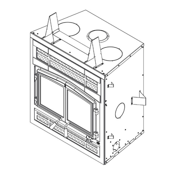
Stratford Fireplace Installation and Operation Manual APPENDIX 1: HEAT DISTRIBUTION KIT INSTALLATION Different heat distribution systems can be installed with the Stratford: • Hot air gravity distribution kit - Traditional style (AC01375) • Hot air gravity distribution kit - Modern with adjustable pipes (AC01389) •... - Page 61 Stratford Fireplace Installation and Operation Manual DIMENSIONS OF HOT AIR OUTLET FRAME WITH ELBOW DIMENSIONS OF HOT AIR OUTLET DECORATIVE GRILLE WITH ELBOW The safety rules and installation procedures for both hot air gravity distribution kits (AC01375, AC01389) are the following: Minimum height*: 68"...
- Page 62 Stratford Fireplace Installation and Operation Manual 62 __________________________________________________________________________...
- Page 63 Stratford Fireplace Installation and Operation Manual The duct system must be installed respecting the following: 1. It is recommended to wear gloves to perform this procedure. Remove the plates closing up the 8" dia. holes on top of the fireplace. Then, cut and remove the insulation in order to obtain two 8" dia. openings.
- Page 64 Stratford Fireplace Installation and Operation Manual to the wall with screws. Secure hot air outlets (F) to the elbows (E) with 3 self-tapping screws each. Secure the hot air outlets grilles to the frames with screws. 4. Maintain at least a 2" (50 mm) clearance between the ducts and the firestop; the required hole size for the hot air grilles (outlet) is 8¼"...
- Page 65 Stratford Fireplace Installation and Operation Manual 8. Do not connect the hot air ducts to a central heating system. Malfunction of the heating system’s fan will cause the fireplace to overheat. 9. Do not use insulated flexible ducts as they may overheat. 10.
- Page 66 Stratford Fireplace Installation and Operation Manual Hot air gravity distribution kit - Modern with adjustable pipes (AC01389) The kit includes: Decorative plate (A) Adjustable frame (B) Heat distribution box (C) Telescoping section (D) Anchor plate (E) All screws are included Parts not included in the kit: 8”...
- Page 67 Stratford Fireplace Installation and Operation Manual DIMENSIONS OF HEAT DISTRIBUTION BOX: DIMENSIONS OF ADJUSTABLE DECORATIVE PLATE: __________________________________________________________________________ 67...
- Page 68 Stratford Fireplace Installation and Operation Manual DIMENSIONS ASSEMBLED HEAT DISTRIBUTION ADJUSTABLE DECORATIVE PLATE: DIMENSIONS OF TELESCOPING SECTION Min. 68 __________________________________________________________________________...
- Page 69 Stratford Fireplace Installation and Operation Manual The duct system must be installed respecting the following: 1. It is recommended to wear gloves to perform this procedure. Remove the plates closing up the 8" dia. holes on top of the fireplace. Then, cut and remove the insulation in order to obtain two 8"...
- Page 70 Stratford Fireplace Installation and Operation Manual Secure the telescoping sections (A) to the heat distribution box (C) with self-tapping screws (B) (3 per telescoping section). Determine the needed height and secure the two parts of the telescoping sections together with 3 self-tapping screws provided. Insert the adjustable frame (D) in the heat distribution box (C), press it against the non-combustible finishing material and secure with 4 screws into the heat distribution box.
- Page 71 (not included in the kit) must be HVAC type pipe and must comply with ULC S110 and/or UL 181, Class 0 or Class 1 Standards and must withstand temperatures up to 250 °F. For the complete installation procedure, www.osburn- see the installation manual provided with the kit. You can also download this manual at mfg.com.
-
Page 72: Appendix 2: Blower Maintenance Or Replacement
Stratford Fireplace Installation and Operation Manual APPENDIX 2: BLOWER MAINTENANCE OR REPLACEMENT 1. Open the bottom louver (A). 2. With short square head screwdriver, remove the 4 screws (C) holding in place the heat shield (B). 72 __________________________________________________________________________... - Page 73 Stratford Fireplace Installation and Operation Manual 3. Remove and keep the heat shield (B) and the 4 screws (C). 4. Cut the Tie wrap (D) __________________________________________________________________________ 73...
- Page 74 Stratford Fireplace Installation and Operation Manual 5. Unplug the blower’s electric wires (F) and (G). 6. Lift the blower (E) located under the firebox towards the back. 7. Turn 90° to pull out. Repeat the steps in reverse order to reinstall the fan.
-
Page 75: Appendix 3: Installing The Optional Door Overlay
Stratford Fireplace Installation and Operation Manual APPENDIX 3: INSTALLING THE OPTIONAL DOOR OVERLAY In order to complete the assembly of your Stratford wood fireplace, you need to install the door overlay. See figure below for installation instructions: Position the overlays (A) and (B) on the door frames and secure them from the inside of the doors using the 10 included nuts (C). -
Page 76: Appendix 4: Installing The Fresh Air Intake Kit
Stratford Fireplace Installation and Operation Manual APPENDIX 4: INSTALLING THE FRESH AIR INTAKE KIT During operation, the fireplace requires fresh air for combustion and draws air out of the house. It may starve other fuel burning appliances such as gas or oil furnaces. As well, exhaust fans may compete for air, causing negative pressure in the house, resulting in smoke entering the house from the fireplace. - Page 77 Stratford Fireplace Installation and Operation Manual Note: Only remove the knock-out that will be connected to the fresh air inlet. The fresh air intake kit may be installed on three different places on the fireplace. 1- On the right side of the appliance (most common). 2- On the right side, at the back of the appliance.
- Page 78 Stratford Fireplace Installation and Operation Manual Flip the fireplace’s lower decorative louver. Install the blocking plate (F) included in the kit, on the front opening of the air control housing. Using a screwdriver, secure with two screws. Then, install the flexible pipe* (D) (not supplied) to the fresh air intake adapter (B) using one of the adjustable pipe clamps (C).
- Page 79 Stratford Fireplace Installation and Operation Manual To complete the installation, make a hole of1/4" to 1/2" (6 mm à 13 mm) bigger than the insulate pipe diameter in the outside wall of the house at the chosen location. From outside, place the outside air inlet cap in the hole (open side down) and fasten the register to the wall, with screws as shown bellow.
-
Page 80: Appendix 5: Installing The Optional Firescreen (Ac01560)
Stratford Fireplace Installation and Operation Manual APPENDIX 5: INSTALLING THE OPTIONAL FIRESCREEN (AC01560) Open the doors. Hold the firescreen by the two handles and bring it close to the door opening. Lean the upper part of the firescreen against the top door opening making sure to insert the top firescreen bracket behind... -
Page 81: Appendix 6: Installation Of Secondary Air Tubes And Baffle
Stratford Fireplace Installation and Operation Manual APPENDIX 6: INSTALLATION OF SECONDARY AIR TUBES AND BAFFLE REMOVABLE PARTS Cotter pins (x4) Air tubes (x4) C-cast baffle (x1) Baffle insulation (x1) Baffle insulation weight (x1) 1. Using a ratchet key and a Torx (T-30), unscrew the two Torx screws (B) holding up the andiron (A). - Page 82 Stratford Fireplace Installation and Operation Manual 2. Remove the floor refractory slab (C). 3. Using a power screwdriver and hex tip 5/16", remove the slab holder (D) and the left refractory slab (E). 82 __________________________________________________________________________...
- Page 83 Stratford Fireplace Installation and Operation Manual 4. Starting with the rear tube, lean and insert the right end of the secondary air tube into the rear right channel hole. Then, lift and push the tube towards the right inside the hole in the right channel.
- Page 84 Stratford Fireplace Installation and Operation Manual 6. Insert a cotter pin in the last hole on the right side of the tube. Then bend the tabs on the pin to keep in place. 7. Repeat steps 4, 5 and 6 for the two tubes in the back then install the baffle.
-
Page 85: Appendix 7: Exploded Diagram And Parts List
Stratford Fireplace Installation and Operation Manual APPENDIX 7: EXPLODED DIAGRAM AND PARTS LIST __________________________________________________________________________ 85... - Page 86 Stratford Fireplace Installation and Operation Manual IMPORTANT: THIS IS DATED INFORMATION. When requesting service or replacement parts for your stove, please provide the model number and the serial number. We reserve the right to change parts due to technology upgrade or availability. Contact an authorized dealer to obtain any of these parts. Never use substitute materials.
- Page 87 Stratford Fireplace Installation and Operation Manual Item Description 30472 SPRING 1/2'' OUTSIDE DIA. X 3''L PL66500 TOP HEAT SHIELD PL63766 HEADER STAND OFF PL53026 AIR INTAKE BOX COVER 30154 BLACK SCREW #10 X 5/8" QUADREX #2 TYPE A OA10330 TRADITIONAL STYLE FACEPLATE OA10332 TRADITIONAL FACEPLATE WITH BRUSHED NICKEL ACCENTS OA10331...
- Page 88 Stratford Fireplace Installation and Operation Manual Refractory slabs Replacement The intense heat of the fire will normally cause hairline cracks in the refractory slabs. These cracks can be minimized by proper curing as described in “First Fires”. They will not normally diminish the effectiveness of the refractory slabs.
- Page 89 Stratford Fireplace Installation and Operation Manual 3- Using a power screwdriver and hex tip 5/16", remove the slab holders (D) and the refractory slabs (E) and (F). 4- Remove the rear refractory slab (G). To install new refractory slabs, follow the above steps in reverse.
- Page 90 Stratford Fireplace Installation and Operation Manual 90 __________________________________________________________________________...
Need help?
Do you have a question about the OB04003 and is the answer not in the manual?
Questions and answers