Table of Contents
Advertisement
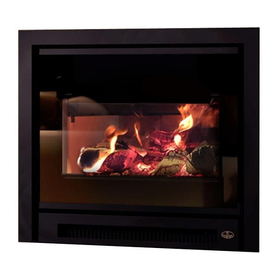
Installation and Operation Manual
INSPIRE 2000-I INSERT
(OB02045 Model)
Safety tested according to
ULC S628, UL 1482 and UL 737
by an accredited laboratory.
CONTACT LOCAL BUILDING OR FIRE OFFICIALS ABOUT RESTRICTIONS AND INSTALLATION INSPECTION REQUIREMENTS IN
LOCAL AREA.
READ THIS ENTIRE MANUAL BEFORE INSTALLATION AND USE OF THIS WOOD INSERT. FAILURE TO FOLLOW THESE
INSTRUCTIONS COULD RESULT IN PROPERTY DAMAGE, BODILY INJURY OR EVEN DEATH.
READ AND KEEP THIS MANUAL FOR REFERENCE
Printed in Canada
45952A
Advertisement
Table of Contents

Related Manuals for Osburn INSPIRE 2000-I OB02045


Summary of Contents for Osburn INSPIRE 2000-I OB02045
- Page 1 Installation and Operation Manual INSPIRE 2000-I INSERT (OB02045 Model) Safety tested according to ULC S628, UL 1482 and UL 737 by an accredited laboratory. CONTACT LOCAL BUILDING OR FIRE OFFICIALS ABOUT RESTRICTIONS AND INSTALLATION INSPECTION REQUIREMENTS IN LOCAL AREA. READ THIS ENTIRE MANUAL BEFORE INSTALLATION AND USE OF THIS WOOD INSERT. FAILURE TO FOLLOW THESE INSTRUCTIONS COULD RESULT IN PROPERTY DAMAGE, BODILY INJURY OR EVEN DEATH.
- Page 3 It is also highly recommended to register the warranty online at https://www.osburn-mfg.com/en/warranty/warranty-registration/ Registering the warranty will help to quickly find the information needed on the unit.
-
Page 4: Table Of Contents
TABLE OF CONTENTS PART A - OPERATION AND MAINTENANCE ................7 1. Safety Information ......................... 7 2. General Information ....................... 8 Performances ........................ 8 Specifications ....................... 9 Dimensions ........................10 Materials ........................11 Zone Heating .......................12 Emissions and Efficiency ....................12 3. Fuel ............................13 Tree Species ........................13 Log Length ........................13 Piece Size ........................13... - Page 5 Appendix 4. Air Tubes and Baffle Installation ................47 Appendix 5. Optional Refractory Panels Installation ............... 49 Appendix 6. Removal Instructions .................... 53 Appendix 7. Exploded Diagram and Parts List ................ 54 OSBURN Limited Lifetime Warranty ..................57 Dealer: Installer: Phone Number:...
- Page 6 CERTIFICATION PLATE Page 6 Installation and Operation Manual - Inspire 2000 Insert...
-
Page 7: Part A - Operation And Maintenance
PART A - OPERATION AND MAINTENANCE 1. Safety Information • Operate only with the door fully closed. If the door is left partly open, gas and flame may be drawn out of the opening, creating risks from both fire and smoke. •... -
Page 8: General Information
2. General Information Performances Values are as measured per test method, except for the recommended heating area, firebox volume, maximum burn time and maximum heat output. Model Inspire 2000-I Insert (OB02045) Fuel Type Dry Cordwood Recommended heating area (sq. ft. 500 to 2,100 ft (47 to 195 m Nominal firebox volume... -
Page 9: Specifications
Specifications Maximum log length 20 in (508 mm) east-west Flue outlet diameter 6 in (150 mm) Recommended connector pipe diameter 6 in (150 mm) Type of chimney ULC S635, CAN/ULC-S640, UL 1777 Baffle material C-Cast Approved for alcove installation Approved for mobile home installation Shipping weight (without option) 420 lb (191 kg) Appliance weight (without option) -
Page 10: Dimensions
Dimensions 28 1/2" 724mm 27" 687mm 13 1/2" 343mm 5 5/8" 142mm 8 1/4" 211mm 20" 6" ø 508mm 150mm Figure 1: Top View Figure 2: Door opening 20 7/8" 530mm 20 5/8" 525mm 20 1/4" 514mm 18 7/8" 9 1/2" 480mm 241mm 8 3/4"... -
Page 11: Materials
3/8" 10mm 16 3/4" 425mm 21" 11 3/4" 533mm 300mm 13 1/2" 344mm Figure 5: Front Firebox Figure 6: Side Firebox Materials The SBI team is committed to protecting the environment, so they do everything they can to use only materials in their products that will have no lasting negative impact on the environment. The body of this insert, which is most of its weight, is carbon steel. -
Page 12: Zone Heating
Zone Heating This insert is a space heater, which means it is intended to heat the area it is installed in, as well as spaces that connect to that area, although to a lower temperature. This is called zone heating and it is an increasingly popular way to heat homes or spaces within homes. -
Page 13: Fuel
3. Fuel Good firewood has been cut to the correct length for the insert, split to a range of sizes and stacked in the open until its moisture content is down to 15% to 20%. DO NOT BURN: - GARBAGE OF ANY KIND, - COAL OR CHARCOAL, - TREATED, PAINTED OR COATED WOOD, - PLYWOOD OR PARTICLE BOARD,... -
Page 14: Compressed Wood Logs
Compressed Wood Logs Compressed wood logs made of 100% compressed sawdust can be burned with caution in the number of these logs burned at once. Do not burn compressed logs made of wax impregnated sawdust or logs with any chemical additives. Follow the manufacturer’s instructions and warnings. -
Page 15: Operating The Insert
4. Operating the Insert Before using the insert, the following steps should be followed: • Install the faceplate (See «Appendix 1. Faceplate Installation») • Plug in the blower power cord. The sleeve (A) and the power cord (B) can be found in the owner’s manual kit. -
Page 16: Blower Operation
Blower Operation A blower is already installed on this insert. It is located behind the bottom louver of the insert. Its function is to increase airflow through the heat exchanger and improve hot air circulation in the room. When used regularly, the blower can provide a small increase in efficiency, up to 2%. -
Page 17: Burning Wood Efficiently
5. Burning Wood Efficiently First Use Two things happen when burning the first few fires; the paint cures and the internal components of the insert are conditioned. As the paint cures, some of the chemicals vaporize. The vapors are not poisonous, but they smell bad. When lighting the insert for the first few times, be prepared by opening doors or windows to ventilate the house. -
Page 18: Combustion Cycles
Place three or four small, split, dry logs in the firebox. Arrange the kindling wood on the logs in two layers at right angles and place a dozen finely split kindling on the second row. It is possible to use ragged paper but it may not hold in place since it tends to roll while it is burning. The best is to wrap a sheet on itself, grab the ends of the roll and make a knot. -
Page 19: Rekindling A Fire
Burning in cycles means the insert door does not need to be opened while the wood is flaming. This is an advantage since it is preventing smoke leaking from the insert when the door is opened as a full fire is burning. This is especially true if the chimney is on the outside wall of the house. -
Page 20: Air Intake Control
If the ashes are disposed of by burial in soil or otherwise locally dispersed, they should be kept in a closed metal container until they are completely cooled. No other waste should be placed in this container. NEVER STORE ASHES INDOORS OR IN A NON-METALLIC CONTAINER OR ON A WOODEN DECK. - Page 21 5.7.2 Long Lasting Fire For a fire that will last up to eight hours but will not produce intense heat, use soft wood and place the logs compactly in the firebox. Before reducing the air intake, the load will have to burn at full heat for long enough for charring the surface of the logs.
-
Page 22: Maintenance
5.7.5 Logs Orientation In a relatively square firebox, the wood can be loaded north-south (ends of the logs visible) or east-west (sides of the logs visible). North-south loads allow more wood to be loaded at the same time. On the other hand, they break into smaller pieces faster. - Page 23 The deposits that form on the glass are the best indication of the fuel quality and success in properly using the insert. These stains can be cleaned with a special wood insert glass cleaner. Do not use abrasive products to clean the insert glass. The goal should be having a clear glass with no brown stains.
- Page 24 6.2.3 Gasket It is a good idea to replace the glass gasket when the door gasket is being replaced. The new gasket is flat, adhesive-backed and made of woven fibreglass. Remove the glass following the first three steps of the «Replacement» section. Remove the old gasket and clean the glass thoroughly.
-
Page 25: Door
Door In order for the insert to burn at its best efficiency, the door must provide a perfect seal with the firebox. The tightness of the door seal can be verified by closing and latching the door on a strip of paper. - Page 26 It is also possible to fix the handle angle by adjusting the door latch mechanism, located on the right hand side opening of the insert. Unscrew the nuts (D) and lift the door latch mechanism (E) to increase the pressure on the door.
-
Page 27: Exhaust System
6.3.2 Gasket It is important to replace the gasket with another having the same diameter and density to maintain a good seal. Remove the door and place it face-down on something soft like a cushion of rags or a piece of carpet. Remove the old gasket from the door. - Page 28 The chimney should be checked regularly for creosote build-up. Inspection and cleaning of the chimney can be facilitated by removing the baffle. See «Appendix 4. Air Tubes and Baffle Installation» for more details. 6.4.3 Chimney Fire Regular chimney maintenance and inspection can prevent chimney fires. If you have a chimney fire, follow these steps: Close the insert door and the air intake control;...
-
Page 29: Part B - Installation
PART B - INSTALLATION 7. Masonry Fireplace Requirements The masonry fireplace must meet the minimum requirements found in the building code enforced locally, or the equivalent, for a safe installation. Contact the local building inspector for requirements in the area. An inspection of the fireplace should include the following: Condition of the fireplace and chimney •... -
Page 30: Safety Information And Standards
Adjacent Combustibles • The fireplace should be inspected to make sure that there is adequate clearance to combustibles, both exposed combustibles to the top, side, and front as well as concealed combustibles, in the chimney and mantle area. The local inspector should have information on whether older fireplaces are of adequate construction. -
Page 31: Certification Label
Certification Label Since the information given on the certification label attached to the appliance always overrides the information published in any other media, it is important to refer to it to have a safe and compliant installation. The model and the serial number can also be found on the label. The certification label is usually located on the side of the insert, towards the front. -
Page 32: Floor Protection
Table 2 : Mantel Shelf Clearances MAXIMUM MANTEL MANTEL SHELF SHELF DIMENSION (X) CLEARANCES (I) 12" (305mm) max. 27" (686 mm) min. Figure 22: Shelf Clearances Floor Protection It is necessary to have a floor protection made of non-combustible materials that meets the measurements specified in the «Table 3 : Floor Protection»... - Page 33 9.2.1 Installation Raised of 5" and Less If non-combustible material floor protection needs to be added in front of and level with the hearth extension of the masonry fireplace (F = 5" or less), an R-value equal to or greater than 1.00 is required and should extend at least 23"...
- Page 34 9.2.3 R Value There are two ways to calculate the R-value of the floor protection. First, by adding the R-values of materials used, or by the conversion if the K factor and thickness of the floor protection are given. To calculate the total R value from R values of the materials used, simply add the R-values of materials. If the result is equal to or greater than the R-value requirements, the combination is acceptable.
-
Page 35: Minimum Masonry Opening And Clearances To Combustibles
Minimum Masonry Opening and Clearances to Combustibles COMBUSTIBLE MANTEL SHELF COMBUSTIBLE TOP SURROUND FLOOR PROTECTION Figure 26: Masonry Opening and Clearances CLEARANCES MINIMUM MASONRY OPENING 24 ⅝" (625 mm) 16" (406 mm) 9" (229 mm) 29" (737 mm)* 27" (686 mm) 20 ¾"... -
Page 36: The Venting System
The Venting System 10.1 General The venting system, made of the chimney and the liner inside the chimney, acts as the engine that drives the wood heating system. Even the best insert will not function safely and efficiently as intended if it is not connected to a suitable chimney and liner system. The heat in the flue gases that pass from the insert into the chimney is not waste heat. -
Page 37: Chimney Liner Installation
10.4 Chimney Liner Installation The use of a chimney liner (rigid or flexible) is recommended RAIN CAP to ensure the best performance. To ensure an optimal draft, it is also strongly recommend adding a minimum of RIGID LINER 12" FLASHING 305mm MIN. - Page 38 The dealer may offer a liner fastening system, sold separately. Follow the installation instructions provided with the liner fastening system. Figure 31: Liner fastening system 10.5.2 Liner Offset Adapter A liner offset adapter, sold separately, can also be installed. This should only be installed if no other option is possible and if the total height of the fireplace and chimney is at least 20 feet.
-
Page 39: Minimum Chimney Height
10.6 Minimum Chimney Height The top of the chimney should be tall enough to be above the air turbulence caused when wind blows against the house and its roof. The chimney must extend at least 1 m (3 ft.) above the highest point of contact with the roof, and at least 60 cm (2 ft.) higher than any roof line or obstacle within a horizontal distance of 3 m (10 ft.). -
Page 40: Supply Of Combustion Air
10.8 Supply of Combustion Air In Canada, wood inserts are not required to have a combustion air supply from outside. Research has shown that outside air supply do not compensate for the depressurization of the house and may not be sufficient to provide a supply of combustion air in windy weather. However, to reduce the risks against smoke spillage due to house depressurization, a carbon monoxide (CO) detector is required in the room where the insert is installed. -
Page 41: Appendix 1. Faceplate Installation
APPENDIx 1. FACEPLATE INSTALLATION Three faceplates are available with this wood insert. For more details about the installation, refer to the faceplate installation instructions. Figure 36: U shaped narrow faceplate Figure 37: Narrow faceplate Figure 38: Cuttable faceplate Installation and Operation Manual - Inspire 2000 Insert Page 41... -
Page 42: Appendix 2. Optional Fresh Air Intake Kit Installation
APPENDIx 2. OPTIONAL FRESH AIR INTAKE KIT INSTALLATION Only remove the knock-out that will be connected to the fresh air inlet. Using pliers, remove the rectangular knockout plate (A) located on the left or right side of the convection air jacket. Choose the side that is best for the installation. Install the fresh air kit adapter (B) using 4 screws (C). -
Page 43: Appendix 3. Blower Replacement
APPENDIx 3. BLOWER REPLACEMENT Unplug the blower and remove all electrical sources on the wood insert. Remove the bottom faceplate by removing the four screws holding it in place. Locate the cover under the wood insert. Installation and Operation Manual - Inspire 2000 Insert Page 43... - Page 44 Push and rotate counterclockwise to remove the cover. Remove both wing nuts (A) holding the blower mounting plate. Page 44 Installation and Operation Manual - Inspire 2000 Insert...
- Page 45 Rotate the blower counterclockwise and gently pull on the blower. Remove both screws (B) and gently pull on the plate (A). Unplug the blower wires (C). Once the blower is unplugged, pull gently for removal. Installation and Operation Manual - Inspire 2000 Insert Page 45...
- Page 46 Blower Rocker switch manual (1) / off (2) / automatic (3) Blue Brown Green/Yellow (ground) Thermal switch (AUTO) (OFF) (MANUAL) Page 46 Installation and Operation Manual - Inspire 2000 Insert...
-
Page 47: Appendix 4. Air Tubes And Baffle Installation
APPENDIx 4. AIR TUBES AND BAFFLE INSTALLATION Starting with the rear tube, lean and insert the right end of the secondary air tube into the rear right channel hole. Then lift and insert the left end of the tube into the rear left channel. Align the notch in the left end of the tube with the key of the left air channel hole. - Page 48 Note that secondary air tubes (B) can be replaced without removing the baffle board (A) and that all tubes are identical. Page 48 Installation and Operation Manual - Inspire 2000 Insert...
-
Page 49: Appendix 5. Optional Refractory Panels Installation
APPENDIx 5. OPTIONAL REFRACTORY PANELS INSTALLATION Remove the center floor bricks (2). Remove the other floor bricks (6). Then, remove the back bottom bricks (2). Installation and Operation Manual - Inspire 2000 Insert Page 49... - Page 50 Remove the back bricks (4), then remove the back left brick (1). Remove the brick retainer (1) and the left bricks (3). Repeat on the right side. Page 50 Installation and Operation Manual - Inspire 2000 Insert...
- Page 51 Remove the retainers (4) and install the back refractory bricks (2). The retainers cannot be reused after being removed so they can be disposed of. Install the sides (2) refractory slabs. Installation and Operation Manual - Inspire 2000 Insert Page 51...
- Page 52 Install the refractory slab retainer (2) on both sides and screw them in place . Install the floor refractory slabs. Page 52 Installation and Operation Manual - Inspire 2000 Insert...
-
Page 53: Appendix 6. Removal Instructions
APPENDIx 6. REMOVAL INSTRUCTIONS For inspecting purposes, the insert may need to be removed. To remove the insert, follow these instructions: Remove the faceplate assembly (C) following the faceplate installation instructions. Remove the screws that secure the flue liner to the fixation brackets (A). Unscrew the levelling bolts (B) located on each side of the wood insert. -
Page 54: Appendix 7. Exploded Diagram And Parts List
APPENDIx 7. ExPLODED DIAGRAM AND PARTS LIST DETAIL A DETAIL B DETAIL C DETAIL D DETAIL G DETAIL E DETAIL H DETAIL F Page 54 Installation and Operation Manual - Inspire 2000 Insert... - Page 55 Screw Pan Torx Type F 1/4-20 X 1" Black PL65853 Door Locking Plate PL65938 Air Intake Casing AC01298 5"Ø Fresh Air Intake Kit Oval 30977 Osburn Sticker SE65915 Bottom Faceplate Assembly SE45952 Inspire Insert Instruction Manual Kit 60331 Power Cord 6' 30484...
- Page 56 Item Description PL65913 Blower Mounting Plate 44207 Double Cage Blower 176 Cfm (Class H) 30131 Black Metal Screw #10 X 1/2" Type "A" Pan Quadrex 30413 Snap Bushing PL65851 Access Panel PL65914 Blower Hood 30221 Lock Nut Hex #8-32 Nylon SE65914 Blower Assembly 22022...
-
Page 57: Osburn Limited Lifetime Warranty
Labour cost and repair work to the account of the manufacturer are based on a predetermined rate schedule and must not exceed the wholesale price of the replacement part. Shall your unit or a components be defective, contact immediately your OSBURN dealer. To accelerate processing of your warranty claim, make sure to have on hand the following information when calling: •... - Page 58 NOTES :...
- Page 60 Resale is strictly prohibited. The manufacturer may update St-Augustin-de-Desmaures (Québec) Canada this document from time to time and cannot be responsible G3A 2H3 for problems, injuries, or damages arising out of the use 418-908-8002 of information contained in any document obtained from https://www.osburn-mfg.com/en/ unauthorized sources. tech@sbi-international.com...
Need help?
Do you have a question about the INSPIRE 2000-I OB02045 and is the answer not in the manual?
Questions and answers