Osburn 2000 Installation And Operation Manual
Hide thumbs
Also See for 2000:
- Installation and operation manual (64 pages) ,
- Owner's manual (39 pages) ,
- Installation and operation manual (60 pages)
Table of Contents
Advertisement
Quick Links
Installation and Operation Manual
CONTACT LOCAL BUILDING OR FIRE OFFICIALS ABOUT RESTRICTIONS AND INSTALLATION INSPECTION REQUIREMENTS IN
LOCAL AREA.
READ THIS ENTIRE MANUAL BEFORE INSTALLATION AND USE OF THIS WOOD INSERT. FAILURE TO FOLLOW THESE
INSTRUCTIONS COULD RESULT IN PROPERTY DAMAGE, BODILY INJURY OR EVEN DEATH.
READ AND KEEP THIS MANUAL FOR FUTURE REFERENCE
Printed in Canada
2000
(OB02016 Model)
Safety tested according to ULC S628,
UL 737 and UL 1482 standards by an
accredited laboratory.
EPA
< ≤
2.5
g/h
45927A
Advertisement
Table of Contents

Related Manuals for Osburn 2000


Summary of Contents for Osburn 2000
- Page 1 Installation and Operation Manual 2000 (OB02016 Model) Safety tested according to ULC S628, UL 737 and UL 1482 standards by an accredited laboratory. < ≤ CONTACT LOCAL BUILDING OR FIRE OFFICIALS ABOUT RESTRICTIONS AND INSTALLATION INSPECTION REQUIREMENTS IN LOCAL AREA.
- Page 3 It is also highly recommended to register the warranty online at https://www.osburn-mfg.com/en/warranty/warranty-registration/ Registering the warranty will help to quickly find the information needed on the unit. Installation and Operation Manual - 2000 Page 3...
-
Page 4: Table Of Contents
8.4 Floor Protection ......................30 8.5 Minimum Masonry Opening and Clearances to Combustibles ..........33 9. The Venting System ........................ 35 9.1 General .........................35 9.2 Block-off Plate ........................35 9.3 Suitable Chimneys ......................35 9.4 Liner Installation ......................36 Page 4 Installation and Operation Manual - 2000... - Page 5 Appendix 7: Optional Fire Screen Installation ................51 Appendix 8: Installation Of Air Tubes And Baffle ..............52 Appendix 9: Removal Instructions ..................... 54 Appendix 10: Exploded Diagram and Parts List ............... 55 Dealer: Installer: Phone Number: Serial Number: Installation and Operation Manual - 2000 Page 5...
- Page 6 CERTIFICATION PLATE Page 6 Installation and Operation Manual - 2000...
-
Page 7: Part A - Operation And Maintenance
• This product can expose you to chemicals including carbon monoxide, which is known to the State of California to cause cancer, birth defects or other reproductive harm. For more information go to www.P65warnings.ca.gov/ Installation and Operation Manual - 2000 Page 7... -
Page 8: General Information
Optimum overall efficiency at a specific burn rate (LHV). This appliance is officially tested and certified by an independent agency. Tested and certified in compliance with CFR 40 part 60, subpart AAA, section 60.534(a)(1(ii) and Draft ASTM WK47329-14. Carbon monoxide. Page 8 Installation and Operation Manual - 2000... -
Page 9: Specifications
CAN/CSA-Z240 MH standard. Tested and certified in compliance with CFR 40 part 60, subpart AAA, section 60.534(a)(1(ii) and Draft ASTM WK47329-14. Installation and Operation Manual - 2000 Page 9... -
Page 10: Dimensions
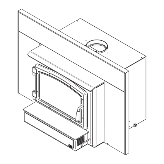
398mm MAX. MIN. 17 1/8" 434mm 10" 25 3/4" 255mm 20 7/8" 655mm 529mm 21 7/8" 556mm 26 3/8" 668mm Figure 3: Front View Figure 4: Side View - Maximum Insert Projection Page 10 Installation and Operation Manual - 2000... - Page 11 3/16" 5/16" 11 7/8" 17 1/2" 301mm 16 3/4" 444mm 425mm 14 1/2" 370mm Figure 5: Door Opening Figure 6: Side Firebox 21" 533mm Figure 7: Front Firebox Installation and Operation Manual - 2000 Page 11...
-
Page 12: Zone Heating And How To Make It Work For You
The body of your insert, which is most of its weight, is carbon steel. Should it ever become necessary many years in the future, almost the entire insert can be recycled into new products, thus eliminating the need to mine new materials. Page 12 Installation and Operation Manual - 2000... -
Page 13: Fuel
People who live in the coldest regions of North America usually have only spruce, birch and poplar, other low-density species to burn and yet they can heat their homes successfully. Installation and Operation Manual - 2000 Page 13... - Page 14 Firewood that is not dry enough to burn is the cause of most complaints about wood inserts. Continually burning green or unseasoned wood produces more creosote and involves lack of heat and dirty glass door. See Section «5. Maintaining your wood heating system» for concerns about creosote. Page 14 Installation and Operation Manual - 2000...
- Page 15 Start with one manufactured log and see how the insert reacts. Never use more than two manufactured logs. Installation and Operation Manual - 2000 Page 15...
-
Page 16: Operating Your Insert
TOXIC WHICH CAN CAUSE DEATH AT HIGH CONCENTRATION IN AIR. 4.3 Blower Operation Ensure the blower cord is not in contact with any surface of the insert to prevent electrical shock or fire damage. Do not run cord beneath the insert. Page 16 Installation and Operation Manual - 2000... -
Page 17: Your First Fires
DO NOT LEAVE THE INSERT UNATTENDED WHEN THE DOOR IS SLIGHTLY OPENED. ALWAYS CLOSE AND LATCH THE DOOR AFTER THE FIRE IGNITES. Installation and Operation Manual - 2000 Page 17... -
Page 18: Maintaining Wood Fires
For example, the area temperature can be cooler when you are active, such as when doing housework or cooking, and it can be warmer when you are inactive, such as when reading or watching television. Page 18 Installation and Operation Manual - 2000... - Page 19 Remove ash first, and then rake charcoal towards the front of the firebox before loading so that it will ignite the new load. Installation and Operation Manual - 2000 Page 19...
- Page 20 With good fuel and correct air control use, the flames should slow down, but should stay large and steady, even as the air supply is reduced. DETAIL A Figure 10: Air Supply Control Page 20 Installation and Operation Manual - 2000...
-
Page 21: Building Different Fires For Different Needs
− the species of wood you burn, − the wood moisture content, − the size of the space to be heated, − the climate zone you live in, and − the time of year. Installation and Operation Manual - 2000 Page 21... - Page 22 East-west loads are excellent for long, low output fires for relatively mild weather. North-south loads break down more quickly, but much more wood can be loaded at a time. This makes north-south loading good for high output, long lasting fires for cold weather. Page 22 Installation and Operation Manual - 2000...
-
Page 23: Maintaining Your Wood Heating System
To adjust: Remove the split pin by pulling and turning it using pliers. Turn the handle counter clock wise one turn to increase pressure. Re-install the split pin with a small hammer. Installation and Operation Manual - 2000 Page 23... - Page 24 Now pinch the gasket to the glass in a U shape, all around the glass. Reinstall the glass, being careful to centre the glass carefully in the door. Page 24 Installation and Operation Manual - 2000...
-
Page 25: Chimney And Chimney Liner Maintenance
Even if creosote forms slowly in your system, the chimney should be cleaned and inspected at least once each year. Installation and Operation Manual - 2000 Page 25... - Page 26 Inspection and cleaning of the chimney is facilitated by the removable baffle. OPERATION OF YOUR INSERT WITHOUT THE BAFFLE MAY CAUSE UNSAFE AND HAZARDOUS TEMPERATURE CONDITIONS AND WILL VOID THE WARRANTY. Page 26 Installation and Operation Manual - 2000...
-
Page 27: Part B - Installation
Your local inspector should have information on whether older fireplaces are of adequate construction. Opening Size Refer to section «8.5 Minimum Masonry Opening and Clearances to Combustibles», page 33 for suitable size fireplace openings. Installation and Operation Manual - 2000 Page 27... -
Page 28: Safety Information
Vents, or CAN/ULC-S640, Standard for Lining Systems for New Masonry Chimneys. The Insert is not approved for use with a so-called “positive flue connection” to the clay tile of a masonry chimney. Page 28 Installation and Operation Manual - 2000... -
Page 29: Clearances To Combustible Material
Note that you can reduce the mantel shelf clearance (distance between the insert and the shelf) with the use of a heat shield, sold separately. See «Appendix 6: Optional Heat Shield Installation» for details. Installation and Operation Manual - 2000 Page 29... -
Page 30: Floor Protection
USA) and at least 18" (457 mm Canada) without an R value. If the hearth elevation is lower than 5" (127 mm), the non-combustible (B) floor protector in front of the insert should have an R value equal or greater than 1.00 and shall extend 23" (584 mm) in front of the unit. Page 30 Installation and Operation Manual - 2000... - Page 31 1.00 is required and should extend at least 23" (584 mm) in front of the unit (B). HEARTH SLAB: NON-COMBUSTIBLE MATERIAL FLOOR PROTECTOR: NON-COMBUSTIBLE MATERIAL Figure 18: 5" or less raised base installation Installation and Operation Manual - 2000 Page 31...
- Page 32 Face brick 9.00 0.11 Marble 14.3 – 20.00 0.07 – 0.05 Ceramic tile 12.5 0.008 Concrete 1.050 0.950 Mineral wool insulation 0.320 3.120 Limestone 0.153 *Information as reported by manufacturers and other resources Page 32 Installation and Operation Manual - 2000...
-
Page 33: Minimum Masonry Opening And Clearances To Combustibles
Figure 20: Masonry Opening and Clearances ** For a 1/8" thickness. You cannot «stack» horizontal still air to accumulate R-values; you must separate each layer of horizontal still air with another non-combustible material. Installation and Operation Manual - 2000 Page 33... - Page 34 «Appendix 6: Optional Heat Shield Installation» for details. ** Where a fresh air intake is needed, we suggest you add a minimum of 4" to the width of the minimum masonry opening. Page 34 Installation and Operation Manual - 2000...
-
Page 35: The Venting System
Otherwise, the diameter of the flue should be 6 inches. The reduction of liner diameter to less than 6" should only be done if the total height of the masonry chimney is greater than 20 feet. Installation and Operation Manual - 2000 Page 35... -
Page 36: Liner Installation
The long end of the brackets must be attached to the insert. Insert the chimney liner into the flue collar of the unit and secure the liner to the brackets with three self-tapping screws (not included). Page 36 Installation and Operation Manual - 2000... - Page 37 The long end of the brackets must be attached to the insert. The brackets and screws are in the insert’s owner’s manual kit. Then follow the instructions in the manual provided with the liner offset adapter kit. Installation and Operation Manual - 2000 Page 37...
-
Page 38: Minimum Chimney Height
If there is no fire burning in a heater connected to a chimney that is shorter than the warm space inside the house, the slight negative pressure low in the house will compete against the desired upward flow in the chimney. Page 38 Installation and Operation Manual - 2000... -
Page 39: Supply Of Combustion Air
Check the outdoor air duct for soot deposits when the full system is cleaned and inspected at least once each year. Installation and Operation Manual - 2000 Page 39... - Page 40 Figure 30: Air supply in conventional houses Page 40 Installation and Operation Manual - 2000...
-
Page 41: Appendix 1: Ash Lip And Blower Installation
Before installing the blower, open the door and install the ash lip by screwing it in place with 3 screws, located in the user manual kit. DETAIL A Push the blower into the clips located Slide the blower underneath the ash lip. underneath the ash lip. Installation and Operation Manual - 2000 Page 41... -
Page 42: Appendix 2: Door Overlay Installation
Note: It is not necessary to remove the glass to install the overlay. Position the overlay (A) on the door frame (B) and secure it in place from behind using the nuts (C). Page 42 Installation and Operation Manual - 2000... -
Page 43: Appendix 3: Optional Fresh Air Intake Kit Installation
(F) using the other pipe clamp (D). The outside wall termination (F) must be installed outside of your home. The pipe must be HVAC type, insulated, and must comply with ULC S110 and/or UL 181, Class 0 or Class 1. Installation and Operation Manual - 2000 Page 43... -
Page 44: Appendix 4: Optional Faceplate And Trims Installation
Place the faceplate panels with the finished side down on a flat, soft, non-abrasive surface. Line up the holes of the upper faceplate panel (A) with the holes of the side panels (B) and (C). Secure them together using four bolts (D) and nuts (E) provided. Page 44 Installation and Operation Manual - 2000... - Page 45 Secure the trim to the faceplate by squeezing right edge of the faceplate and slowly slide it the eight trim retainers (L) between the inner down over the faceplate. edge of the trim and the front of the faceplate. Installation and Operation Manual - 2000 Page 45...
- Page 46 Align the holes in the faceplate extension (M) with the holes in each faceplate side panels. DETAIL A Secure both assemblies together using 6 bolts (N) and nuts (O) provided. Page 46 Installation and Operation Manual - 2000...
- Page 47 (Q). Then push towards the fireplace. 11. Once the faceplate is in place, secure the assembly by tightening nuts (R) using a 7/16" (11 mm) open end wrench. Installation and Operation Manual - 2000 Page 47...
-
Page 48: Appendix 5: Optional Cuttable Faceplate Installation
This 18G steel faceplate is cuttable to the desired shape of the fireplace opening if it contains irregular edges (e.g.: fieldstones). The use of a template may be useful prior to cutting of the faceplate. See the installation manual provided with the faceplate. Page 48 Installation and Operation Manual - 2000... -
Page 49: Appendix 6: Optional Heat Shield Installation
MAXIMUM MANTEL MANTEL SHELF SHELF DIMENSION (X) CLEARANCES (I) 12" (305mm) max. 21" (533 mm) min. COMBUSTIBLE MANTEL SHELF COMBUSTIBLE TOP SURROUND TOP SURROUND CLEARANCES (H) 21" (533 mm) min. FLOOR PROTECTION Installation and Operation Manual - 2000 Page 49... - Page 50 Install the heat shield on the faceplate (assembled with the faceplate extension) using 3 self- drilling screws included in the kit. The heat shield should be pointing upwards. Once the heat shield is positioned, install the faceplate on the insert. Page 50 Installation and Operation Manual - 2000...
-
Page 51: Appendix 7: Optional Fire Screen Installation
Lift the fire screen upwards and push the bottom part towards the stove then let the fire screen rest on the bottom of the door opening. Warning: Never leave the stove unattended while in use with the fire screen. Installation and Operation Manual - 2000 Page 51... -
Page 52: Appendix 8: Installation Of Air Tubes And Baffle
Repeat steps 1 and 2 for the two tubes in the back then install the baffle before installing the two front tubes. To remove the tubes use the above steps in reverse order. Page 52 Installation and Operation Manual - 2000... - Page 53 Note that secondary air tubes (A) can be replaced without removing the baffle board (B) and that all tubes are identical. SECTION D-D Installation and Operation Manual - 2000 Page 53...
-
Page 54: Appendix 9: Removal Instructions
Remove the blower assembly (D) by pulling on it. Remove the three screws securing the pipe connector (A). Unscrew the bolts securing the insert to the floor on each side of the unit (E). Page 54 Installation and Operation Manual - 2000... -
Page 55: Appendix 10: Exploded Diagram And Parts List
APPENDIX 10: EXPLODED DIAGRAM AND PARTS LIST Installation and Operation Manual - 2000 Page 55... - Page 56 44028 CERAMIC THERMODISC F110-20F SE65057 BLOWER ASSEMBLY 60013 POWER CORD 96" X 18-3 type SJT 44085 RHEOSTAT KNOB 44087 RHEOSTAT NUT 44080 RHEOSTAT WITHOUT NUT AC01298 5" FRESH AIR INTAKE KIT OVAL Page 56 Installation and Operation Manual - 2000...
- Page 57 FACEPLATE EXTENSION PL65061 RIGHT OR LEFT SIDE DECORATIVE PANEL SE15097 FACEPLATE HARDWARE KIT SE45927 OSBURN 2000 INSERT INSTRUCTIONS MANUEL KIT AC01317 7 3/16" X 26" HEAT SHIELD FOR SURROUND/SHELF AC03411 LARGE FACEPLATE (32" X 50") AC03410 REGULAR FACEPLATE (29" X 44") OA10123 BRUSHED NICKEL FACEPLATE TRIMS (29"...
- Page 58 Labour cost and repair work to the account of the manufacturer are based on a predetermined rate schedule and must not exceed the wholesale price of the replacement part. Shall your unit or a components be defective, contact immediately your OSBURN dealer. To accelerate processing of your warranty claim, make sure to have on hand the following information when calling: •...
- Page 60 Resale is strictly prohibited. The manufacturer may update St-Augustin-de-Desmaures (Québec) Canada this document from time to time and cannot be responsible G3A 2H3 for problems, injuries, or damages arising out of the use 418-908-8002 of information contained in any document obtained from www.osburn-mfg.com/en unauthorized sources. tech@sbi-international.com...
Need help?
Do you have a question about the 2000 and is the answer not in the manual?
Questions and answers