Osburn STRATFORD Installation Instructions Manual
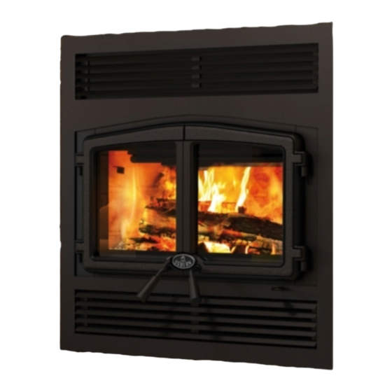
Osburn stratford fireplace
Hide thumbs
Also See for STRATFORD:
- Installation and operation manual (94 pages) ,
- Installation instructions manual (47 pages) ,
- Installation and operation manual (90 pages)
Table of Contents
Advertisement
Quick Links
Installation Instructions
This installation manual will help you obtain a safe, efficient, dependable installation for your fireplace and
chimney system. Please read and understand these installation instructions before beginning your installation.
CAUTION: Do not attempt to modify or alter the construction of the fireplace or its components. Any
modification or alteration of construction may void the warranty, listings and approvals of this system. In that
case, Stove Builder International (SBI) will not be responsible for damages. Install the fireplace only as
described in these instructions.
PLEASE RETAIN THIS MANUAL FOR FUTURE REFERENCE
Manufactured by: STOVE BUILDER INTERNATIONAL INC.
250, de Copenhague, Saint-Augustin-de-Desmaures (Quebec), Canada G3A 2H3
This manual is available for free download on the manufacturer's web site. It is a
copyrighted document. Re‐sale is strictly prohibited. The manufacturer may update this
manual from time to time and cannot be responsible for problems, injuries, or damages
arising out of the use of information contained in any manual obtained from unauthorized
sources.
Printed in Canada
MODEL OSBURN STRATFORD
Tel: (418) 878-3040 Fax: (418) 878-3001
Listed to standards
ULC-S610 and UL-127
45178A
18-04-2013
Advertisement
Table of Contents

Related Manuals for Osburn STRATFORD


Summary of Contents for Osburn STRATFORD
-
Page 1: Installation Instructions
MODEL OSBURN STRATFORD Installation Instructions This installation manual will help you obtain a safe, efficient, dependable installation for your fireplace and chimney system. Please read and understand these installation instructions before beginning your installation. CAUTION: Do not attempt to modify or alter the construction of the fireplace or its components. Any modification or alteration of construction may void the warranty, listings and approvals of this system. -
Page 2: Table Of Contents
2.1.1 Parts Required ........................5 2.1.2 Additional Equipment (optional) ..................5 OPERATING THE OSBURN STRATFORD ..............6 2.2.1 Fuel ............................ 6 2.2.2 The use of manufactured logs .................... 6 ... - Page 3 OPTIONS ....................... 52 APPENDIX ......................53 SPECIFICATIONS ......................53 CLEARANCE TO COMBUSTIBLES ................53 THERMAL CHARACTERISTICS OF COMMON FLOOR PROTECTION MATERIALS* ........................54 OSBURN LIMITED LIFETIME WARRANTY ............57 ...
-
Page 4: Model Osburn Stratford
Canada by WETT (Wood Energy Technical Training) or in Quebec by APC (Association des Professionnels du Chauffage). Use only an Osburn glass door, specifically designed for the model Osburn Stratford. When cleaning the fireplace, the ashes should be placed in a metal container with a tight fitting lid. - Page 5 To receive full warranty coverage, you will need to show evidence of the date you purchased your unit. Keep your sales invoice. We also recommend that you register your warranty online at http://www.osburn-mfg.com/warranty-registration.aspx Registering your warranty online will help us track rapidly the information we need on your unit.
-
Page 6: The Fireplace
2. The OSBURN STRATFORD is not intended for use with a gas log. Failure to follow these instructions will void the certification and the warranty of the fireplace and may result in an unsafe installation. -
Page 7: Operating The Osburn Stratford
OPERATING THE OSBURN STRATFORD 2.2.1 Fuel The OSBURN STRATFORD is designed to work best when fuelled with seasoned cordwood. Use solid wood or processed solid fuel firelogs only. Hardwoods are preferred to softwoods since the energy content of wood is relative to its density. Hardwoods will result in a longer burning fire and less frequent refuelling. -
Page 8: First Fires
Then, bring the red embers to the front of the stove and reload the unit. Your OSBURN STRATFORD fireplace will work best if a thick bed of hot embers is maintained in the bottom of the firebox, and a minimum of two large pieces of seasoned fuel are added. -
Page 9: Primary Air
2.2.6 Primary Air There is no flue damper in the OSBURN STRATFORD. As in common with air tight stoves, the combustion air control sets the flow of air entering the firebox. This allows for a more precise control of the fire. -
Page 10: Combustion Settings
Creosote may accumulate on the glass door. This method of burning should be used only after operating the OSBURN STRATFORD with the air control opened to produce a hot fire for about an hour or at medium pace for at least 2 hours. Slow combustion can be used at night in order to reduce the heat output and to prolong the burn. -
Page 11: Smoking Causes And Troubleshooting
As the fire burns, air goes up the chimney. This air must be replaced through leakage into the house or through the fresh air kit. When operating the OSBURN STRATFORD, open a nearby window temporarily to check if there is adequate air supply replacement. If opening a window solves the problem, the house is under negative pressure. - Page 12 IMPORTANT NOTES A. Do not block the hot air vents to the fireplace as this will cause the fireplace to overheat. B. Never start a fire using gasoline, kerosene, charcoal lighter fluid or any other combustible liquid. C. Do not burn coal. The sulphur in coal will corrode the firebox. D.
-
Page 13: Maintaining Your Osburn Stratford
MAINTAINING YOUR OSBURN STRATFORD 2.3.1 Creosote – Formation and Need for Removal When wood is burned slowly without a flame, it produces tar and other organic vapours which combine with expelled moisture to form creosote. The creosote vapours condense in; the relatively cool chimney flue of a slow-burning fire. -
Page 14: Dealing With A Chimney Fire
2. Lift the baffle and slide it out of the fireplace. You now have access to the chimney. Figure 2 2.3.4 Dealing with a Chimney Fire Regular chimney maintenance and inspection can prevent chimney fires. If you have a chimney fire, follow these steps: 1. -
Page 15: Plated Finish Maintenance
2.3.8 Glass Care – Replacement The two glasses used in the OSBURN STRATFORD are 5 mm thick and have the same dimension of 13.188" H x 11.875" W. They are tested to reach temperatures up to 1400º F. If a glass breaks, it must be replaced with one having the same specification. - Page 16 WARNING: TEMPERED GLASS OR ORDINARY GLASS WILL NOT WITHSTAND THE HIGH TEMPERATURES OF THE OSBURN STRATFORD. WARNING: DO NOT ABUSE THE GLASS DOOR BY SLAMMING IT AGAINST THE FIREPLACE. WARNING: DO NOT OPERATE THE FIREPLACE WITH A CRACKED OR BROKEN GLASS.
-
Page 17: Glass Care - Cleaning
2.3.9 Glass Care – Cleaning The OSBURN STRATFORD is designed to keep the glass clean under normal operating conditions. If the OSBURN STRATFORD is operated continuously with the combustion air controls closed, the glass will tend to get dirty unless the fuel, firebox and glass are maintained at higher temperatures. -
Page 18: Heart Extension Requirements
Note the floor construction and consult your local building code to determine if additional support is needed. C. The OSBURN STRATFORD may be installed directly on the floor or on a raised base (for proper guidelines, refer to “Heart Extension Requirements”) and a minimum of 7 feet (2.15 m) measured from the base of the appliance to the ceiling is required. - Page 19 Figure 7 Figure 8 When the fireplace is installed directly on the floor, a noncombustible floor protection in front of the unit must be installed and have an R value insulation equal to or greater than 1.00. The use of an R value is convenient when more than one material is going to be used in the hearth extension to cover the combustible surface.
-
Page 20: R Calculations
2.4.2.1 R Calculations There are two ways to calculate the R factor of the floor protection. First, by adding the R-values of the proposed materials or if some K and thickness values are given, by converting them to R values. To calculate the R factor for a composite floor protection made of a combination of alternative materials, simply add the R-values of those materials. -
Page 21: How To Eliminate The Need Of A R Value
In the case of a known K and thickness of alternative materials to be used in combination, convert all K values to R by dividing the thickness of each material by its K value. Add the R values of your proposed materials as shown in the previous example. Example: K value = 0.75 Thickness = 1... -
Page 22: Framing, Facing, Mantel, And Combustible Shelf
2.4.3 Framing, Facing, Mantel, and Combustible Shelf Framing The construction of the framing, facing, and mantel must be in accordance with the standards and the following illustrations (figures 10 to 14): A. Frame the fireplace using 2" × 3" (5 cm x 8 cm) or heavier lumber. WARNING: COMBUSTIBLE FRAMING MATERIAL CANNOT BE USED IN THE SPACE DIRECTLY ABOVE THE FIREPLACE, EXCEPT FOR THE STUDS ABOVE THE FACING THAT SUPPORT THE FACING MATERIAL AND MANTEL. - Page 23 Figure 10 Figure 11...
- Page 24 Figure 12 Figure 13...
- Page 25 Figure 14...
-
Page 26: Insulated Chase Construction
INSULATED CHASE CONSTRUCTION FIREPLACE Figure 15 Facing 1. Materials directly in contact with the faceplate of the fireplace, especially the vertical and horizontal surround, must be non-combustible and have the minimal dimensions as shown on figure 16. 2. Non-combustible materials such as brick, stone or ceramic tile may project in front of and onto the fireplace decorative frame. - Page 27 Caution: Materials must be installed so that the faceplate may be removed after the installation. The faceplate is designed to overlap the material surrounding the fireplace. If the material is thicker, use a faceplate gauge for positioning and make sure that the faceplate can be removed after it has been installed.
- Page 28 Combustible shelf To install any combustible shelf, refer to figure 17 for a safe installation. For example, a shelf with a 6’’ depth (152 mm) must be installed at least 50" (127 cm) above the base of the fireplace. Different shelf dimensions are listed in figure 17 in order to facilitate installation.
- Page 29 Figure 18...
-
Page 30: Blower Connection
2.4.4 Blower connection The fan will come on as soon as the fireplace reaches its minimum start temperature. Have the wiring installed by a qualified electrician. Connect the wires from the power outlet to the terminal block, making sure that the white wire matches the white wire on the terminal. Connect the black wire with the black wire of the terminal block. -
Page 31: Hot Air Ducting Installation
HOT AIR DUCTING INSTALLATION Different hot air ducting systems can be installed with the OSBURN STRATFORD: Gravity kit Forced air kit 2.5.1 Gravity Kit The kit includes: 2 x hot air outlets (grilles and frames); 2 x 90 elbows with brackets;... - Page 32 The hot air grilles can be installed in the same room as the fireplace, or one or both of the grilles can be installed in adjacent or upper rooms. Installing the ducts at different elevations will tend to exhaust more heat out of the higher grilles (figure 23). Figure 22 Figure 23...
-
Page 33: Central Forced Air Kit (Not Tested Under Epa Certification)
2.5.2 Central Forced Air Kit (Not tested under EPA certification) The knock-outs provided on the back and on the sides of the OSBURN STRATFORD allow the connection of insulated flexible pipe which enables you to heat adjacent rooms up to 50 feet from the fireplace (see figure 26). - Page 34 D) Attach a flexible pipe to the fan’s air outlet and route the flexible pipe to the chosen location. The ducting system can be installed either in an upper room or in a lower room; E) At that point, the flexible pipe can be attached to any air distribution grille. F) Make the electrical connections to the PC Board as explained with the forced air kit owner’s manual.
-
Page 35: Fresh Air Kit (Optional)
FRESH AIR KIT (OPTIONAL) During operation, the fireplace requires fresh air for combustion and draws air out of the house. It may starve other fuel burning appliances such as gas or oil furnaces. As well, exhaust fans may compete for air, causing negative pressure in the house, resulting in smoke entering the house from the fireplace. - Page 36 OUTSIDE AIR FRESH AIR INTAKE CONNECTION TO THE FIRE PLACE FIREPLACE CONNECTION ALUMINUM OUTSIDE TAPE INTAKE FIREPLACE ALUMINUM TAPE PLASTIC COVER 3" FLEXIBLE PIPE PLASTIC COVER FLEXIBLE PIPE SCREW OPENING FACING DOWN INSULATION ALUMINUM INSULATION WALL ALUMINUM TAPE TAPE Figure 27 Figure 28 1) Remove the bottom louver 2) Seal the room air intake located on the right side...
-
Page 37: Door Overlay Installation
Figure 33 Figure 32 DOOR OVERLAY INSTALLATION In order to install the door overlay, simply put the overlay on the door frame. Then, pass the 4 bolts through the holes shown in figure 34. Finally, secure the door overlay in place using the 4 nuts. -
Page 38: Door Alignment
DOOR ALIGNMENT To adjust the door positioning and spacing, loosen the hinge screw and pivot the hinge until the door is in the correct position. To tilt the door, lock in place one of the two hinges and pivot the other. -
Page 39: Optional Fire Screen Installation (Ac01308)
OPTIONAL FIRE SCREEN INSTALLATION (AC01308) Open the doors. Hold the fire screen by the two handles and bring it close to the door opening. Lean the upper part of the fire screen against the top door opening making sure to insert the top fire screen bracket behind primary... -
Page 40: The Chimney
Installations, which are located on lower floors in the house, such as in a basement, in combination with outside chimney, are especially prone to flow reversal. 2. The OSBURN STRATFORD is listed only with chimney systems described in table 1. 3. A chimney venting a fireplace shall not vent any other appliance. - Page 41 Figure 36a Figure 36b...
- Page 42 12. When you build a chase enclosure for chimney sections above the roof, the chimney must extend at least 3 ft. (92 cm) above the chase enclosure and at least 2 ft. (61 cm) higher than any wall, roof or building within 10 ft. (3.1 m) of it. See Figure 36c and 36d to determine the configuration that applies to your roof (flat or sloped roof and the distance between the chimney and the highest point of the roof and/or the nearest chimney).
-
Page 43: Chimney Installation Instructions
CHIMNEY INSTALLATION INSTRUCTIONS Cut and frame the holes in the ceiling, floor and roof where the chimney will pass and install rafter protectors (see figure 37). Use a plumb bob to line up the center of the holes. Make sure that the size of the floor and ceiling holes are in accordance with the chimney manufacturer’s instructions. - Page 44 8. When a ventilated roof flashing is installed, precautions are to be taken not to caulk or seal the ventilating openings. EXAMPLE OF TYPICAL CHIMNEY INSTALLATION Figure 38...
-
Page 45: Offset Chimney Installation
OFFSET CHIMNEY INSTALLATION The minimum chimney height when using elbows is: Fireplace model OSBURN STRATFORD Chimney model All models Vertical installation 15 ft. (4.6 m)* Two (2) elbows 15 ft. (4.6 m)* Four (4) elbows 17 ft. (5.2 m)* Table 1 *Including the height of the fireplace itself. - Page 46 Figure 40 Figure 41...
- Page 47 TABLE 2 - LISTED CHIMNEYS FOR YOUR OSBURN STRATFORD CHIMNEY BRAND TYPE INNER DIAMETER MANUFACTURER Selkirk Ultra-Temp (UT) 1” Solid Pack 6" (15 cm) Selkirk Super Pro (SPR) 1” Solid Pack 6" (15 cm) Selkirk Super Vent (JSC) 1” Solid Pack 6"...
- Page 48 Inner diameter 6″ Inner diameter 7″ Reference Parts required. (The numbers in brackets Figure are the parts numbers used by Security 1″ 2″ 1″ 2″ Chimneys) insulation insulation insulation insulation (ASHT+) (S2100+) (ASHT+) (S2100+) Anchor Plate (6SP) Anchor Plate (6XSP) Screws 6″...
-
Page 49: Angled Wall Radiation Shield
ANGLED WALL RADIATION SHIELD When passing through a combustible wall with the chimney at a 30 or 45 angle (30 or 45 in Canada and 30 only in the USA), an angled firestop or wall radiation shield provided by the chimney manufacturer must be installed. -
Page 50: Chimney Support Installation
CHIMNEY SUPPORT INSTALLATION Universal Roof Support This support has three possible uses: 1. It must be used on a roof to support the chimney. 2. It may be used on a floor, ceiling or roof above an offset to support the chimney above the offset. -
Page 51: Chimney Chase And Multiple Terminations
CHIMNEY CHASE AND MULTIPLE TERMINATIONS For the purpose of this manual, a chimney chase is considered a part of the chimney system rather than part of a building. The termination must be placed a minimum of 18" (460 mm) above the chase. -
Page 52: Installation Instructions For Masonry Application
INSTALLATION INSTRUCTIONS FOR MASONRY APPLICATION WARNING: Before starting the installation, the masonry chimney must be inspected by a qualified sweep. The following requirements must be respected: 1. The chimney must be absolutely clear of any soot residue or creosote. Check for cracks, loose or missing bricks that could inhibit correct installation of the liner. -
Page 53: Options
OPTIONS Gravity kit: Part No.: Includes: one deflector, two 90 elbows, and two outlet grilles and frames, #AC01309 Central forced air kit: Includes: one blower, one 5" flex adapter, 3 pipe clamps, and one control box with heat sensor and PC Board. #AC01310 Outside air kit Includes: one 3"... -
Page 54: Appendix
APPENDIX SPECIFICATIONS Weight: 385 lbs Height: 38" Width: 36¾" Depth: 26" Maximum recommended heating area: 500 to 2,100 square feet (with forced air kit) Heating capacity* – BTU/hr., EPA test wood: 30,500 Heating capacity* – BTU/hr., seasoned cordwood: 75,000 Optimum efficiency: 77% *Why is the BTU indicated on the EPA label smaller than the one advertised? You will notice a difference between the BTU output as indicated on the unit’s white EPA label affixed to the glass and the BTU as advertised on our web site and/or product literature. -
Page 55: Thermal Characteristics Of Common Floor Protection Materials
THERMAL CHARACTERISTICS OF COMMON FLOOR PROTECTION MATERIALS* MATERIAL CONDUCTIVITY RESISTANCE (R) PER INCH (k) PER INCH THICKNESS Micore® 160 0.39 2.54 Micore® 300 0.49 2.06 Durock® 1.92 0.52 Hardibacker® 1.95 0.51 Hardibacker® 500 0.44 Wonderboard® 3.23 0.31 Cement mortar 5.00 Common brick 5.00 Face brick... - Page 56 Exploded view for replacement parts...
- Page 57 BRUSHED NICKEL CAST IRON DOOR OVERLAY 30123 SCREW #8 - 32 X 5/8'' PAN QUADREX ZINC 30569 BLACK ROUND WOODEN HANDLE SE24160 STRATFORD LEFT DOOR WITH HANDLE AND GASKET PL53100 FIREPLACE RIGHT DOOR HANDLE ROD 30039 NUT 1/2-20 AC06500 SILICONE AND 5/8" X 8' BLACK GASKET KIT...
-
Page 58: Osburn Limited Lifetime Warranty
Paint (peeling), gaskets, insulation, firebrick, and ceramic fibre blankets. 1 year *Pictures required Shall your unit or a components be defective, contact immediately your OSBURN dealer. Prior to your call make sure you have the following information necessary to your warranty claim treatment: ...
Need help?
Do you have a question about the STRATFORD and is the answer not in the manual?
Questions and answers