Table of Contents
Advertisement
Quick Links
INSTALLATION AND OPERATION MANUAL
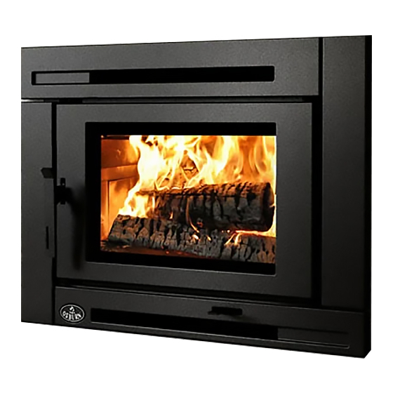
MATRIX
Insert
250, rue de Copenhague, St‐Augustin‐de‐Desmaures (Quebec) Canada G3A 2H3
This manual is available for free download on the manufacturer's web site. It is a copyrighted
document. Re‐sale is strictly prohibited. The manufacturer may update this manual from time to
time and cannot be responsible for problems, injuries, or damages arising out of the use of
information contained in any manual obtained from unauthorized sources.
Printed in Canada
www.osburn‐mfg.com
Stove Builder International Inc.
Tel: (418) 878‐3040 Fax: (418) 878‐3001
READ AND KEEP THIS MANUAL FOR REFERENCE
US ENVIRONMENTAL PROTECTION
AGENCY PHASE II CERTIFIED
WOOD INSERT
Safety tested according to ULC S628,
UL 737 and UL 1482 Standards
by Intertek Testing Services
45593A
05‐03‐2013
Advertisement
Table of Contents

Related Manuals for Osburn Matrix insert


Summary of Contents for Osburn Matrix insert
- Page 1 www.osburn‐mfg.com Stove Builder International Inc. 250, rue de Copenhague, St‐Augustin‐de‐Desmaures (Quebec) Canada G3A 2H3 Tel: (418) 878‐3040 Fax: (418) 878‐3001 This manual is available for free download on the manufacturer’s web site. It is a copyrighted document. Re‐sale is strictly prohibited. The manufacturer may update this manual from time to time and cannot be responsible for problems, injuries, or damages arising out of the use of ...
- Page 2 Matrix Insert Installation and Operation Manual THANK YOU FOR CHOOSING THIS OSBURN WOOD INSERT As one of North America’s largest and most respected wood stove and fireplace manufacturers, Stove Builder International takes pride in the quality and performance of all its products. We want to help you get maximum satisfaction as you use this product. In the pages that follow you will find general advice on wood heating, detailed instructions for safe and effective installation, and guidance on how to get the best performance from this insert as you build and maintain fires, and maintain your wood heating system. We recommend that our wood burning hearth products be installed and serviced by professionals ® who are certified in the United States by NFI (National Fireplace Institute ) or in Canada by WETT (Wood Energy Technology Transfer) or in Quebec by APC (Association des Professionnels du Chauffage). ...
-
Page 3: Table Of Contents
Matrix Insert Installation and Operation Manual Table of content PART A ‐ OPERATION AND MAINTENANCE .......... 6 Safety Information ................ 6 Summary of Operation and Maintenance Cautions and Warnings ........ 6 General Information ................. 8 Matrix Insert Specifications .................... 8 Zone Heating and How to Make it Work for You .............. 1 0 The Benefits of Low Emissions and High Efficiency ............. 1 1 The SBI Commitment to You and the Environment ............ 1 1 ... - Page 4 Matrix Insert Installation and Operation Manual 4.4.4 Firing Each New Load Hot .................... 2 1 4.4.5 Turning Down the Air Supply ................... 2 1 Fan Operation ........................ 2 2 4.5.1 Building Different Fires for Different Needs .............. 2 2 Maintaining Your Wood Heating System ......... 25 Insert Maintenance ...................... 2 5 5.1.1 Cleaning Door Glass ...................... 2 5 ...
- Page 5 9.8.1 Air Supply in Conventional Houses .................. 4 7 Appendix 1: Reversing the Door Opening and Adjusting the Handle .. 48 Appendix 2: Installing the Adapter for Fresh Air Kit (AC01298) ..... 50 Appendix 3: Faceplate Installation ............ 51 Appendix 4: Blower Installation ............ 53 Appendix 5: Installing the Fire Screen (AC01315) ......... 55 Appendix 6: Installation of Secondary Air Tubes and Baffle .... 56 Appendix 7: Removal instructions ............ 58 Appendix 8: Exploded Diagram and Parts List ........ 59 OSBURN LIMITED LIFETIME WARRANTY .......... 62 _ ______________________________________________________________________________ 5 ...
-
Page 6: Part A - Operation And Maintenance
Matrix Insert Installation and Operation Manual PART A ‐ OPERATION AND MAINTENANCE Please see Part B for installation instructions. 1 SAFETY INFORMATION 1.1 SUMMARY OF OPERATION AND MAINTENANCE CAUTIONS AND WARNINGS • HOT WHILE IN OPERATION, KEEP CHILDREN, CLOTHING AND FURNITURE AWAY. CONTACT MAY CAUSE SKIN BURNS. GLOVES MAY BE NEEDED FOR INSERT OPERATION. • USING AN INSERT WITH CRACKED OR BROKEN COMPONENTS, SUCH AS GLASS OR FIREBRICKS OR BAFFLES MAY PRODUCE AN UNSAFE CONDITION AND MAY DAMAGE THE INSERT. ... - Page 7 Matrix Insert Installation and Operation Manual • DO NOT BURN: o GARBAGE OF ANY KIND, o COAL OR CHARCOAL, o TREATED, PAINTED OR COATED WOOD, o PLYWOOD OR PARTICLE BOARD, o FINE PAPER, COLORED PAPER OR CARDBOARD, o SALT WATER DRIFTWOOD, o MANUFACTURED LOGS CONTAINING WAX OR CHEMICAL ADDITIVES, o RAILROAD TIES OR o LIQUIDS SUCH AS KEROSCENE OR DIESEL FUEL TO START A FIRE. • THIS APPLIANCE SHOULD BE MAINTAINED AND OPERATED AT ALL TIMES IN ACCORDANCE WITH THESE INSTRUCTIONS. • DO NOT ELEVATE THE FIRE BY MEANS OF GRATES, AND IRONS OR OTHER MEANS. • SOME JURISDICTIONS IN THE USA REQUIRE A SUPPLY OF OUTDOOR COMBUSTION AIR FOR ...
-
Page 8: General Information
Matrix Insert Installation and Operation Manual 2 GENERAL INFORMATION 2.1 MATRIX INSERT SPECIFICATIONS Fuel Type Cordwood Test Standards (safety) ULC S628, UL 737 and UL 1482 Test Standard (emissions) EPA Method 28 (40 CFR Part 60) Heating capacity range* 500 to 2100 sq. ft. (47 to 195 m ) Maximum heat output** 32 200 BTU/h (9,4 kW/h) (EPA test fuel) Maximum heat output** 75 000 BTU/h (22 kW/h) (natural hardwood fuel) Optimum efficiency 77,2 % Test Standard (efficiency) CSA B415.1‐10 Approximate Burn Time 6 to 8 hours Shipping Weight 480 lb ( 218 kg) Firebox Volume 2,4 cu.ft. (0,068 m ) Maximum Log Length 20" east‐west*** Flue Outlet Diameter 6" (150 mm) diameter (vertical) Baffle Material C‐Cast * Burn time and heating capacity may vary subject to location in home, chimney draft, chimney diameter, locality, heat loss factors, climate, fuels and other variables. ... - Page 9 Matrix Insert Installation and Operation Manual _ ______________________________________________________________________________ 9 ...
-
Page 10: Zone Heating And How To Make It Work For You
Matrix Insert Installation and Operation Manual 2.2 ZONE HEATING AND HOW TO MAKE IT WORK FOR YOU Your new Matrix wood insert is a space heater, which means it is intended to heat the area it is installed in, as well as spaces that connect to that area, although to a lower temperature. This is called zone heating and it is an increasingly popular way to heat homes or spaces within homes. Zone heating can be used to supplement another heating system by heating a particular space within a home, such as a basement family room or an addition that lacks another heat source. Houses of moderate size and relatively new construction can be heated with a properly sized and located wood insert. Whole house zone heating works best when the insert is located in the part of the house where the family spends most of its time. This is normally the main living area where the kitchen, dining and living rooms are located. By locating the insert in this area, you will get the maximum benefit of the heat it produces and will achieve the highest possible heating efficiency and comfort. The space where you spend most of your time will be warmest, while bedrooms and basement (if there is one) will stay cooler. In this way, you will burn less wood than with other forms of heating. ... -
Page 11: The Benefits Of Low Emissions And High Efficiency
Matrix Insert Installation and Operation Manual 2.3 THE BENEFITS OF LOW EMISSIONS AND HIGH EFFICIENCY The low smoke emissions produced by the special features inside the Matrix insert mean that your household will release up to 90 percent less smoke into the outside environment than if you used an older conventional stove. But there is more to the emission control technologies than protecting the environment. The smoke released from wood when it is heated contains about half of the energy content of the fuel. By burning the wood completely, your insert releases all the heat energy from the wood instead of wasting it as smoke up the chimney. Also, the features inside the firebox allow you to reduce the air supply to control heat output, while maintaining clean and efficient flaming combustion, which boosts the efficient delivery of heat to your home. ... - Page 12 Matrix Insert Installation and Operation Manual The door glass is a 5 mm thick ceramic material that contains no toxic chemicals. It is made of natural raw materials such as sand and quartz that are combined in such a way to form a high temperature glass. Ceramic glass cannot be recycled in the same way as normal glass, so it should ...
-
Page 13: Fuel
Matrix Insert Installation and Operation Manual 3 FUEL 3.1 MATERIALS THAT SHOULD NOT BE BURNED • GARBAGE OF ANY KIND, • COAL OR CHARCOAL, • TREATED, PAINTED OR COATED WOOD, • PLYWOOD OR PARTICLE BOARD, • FINE PAPER, COLORED PAPER OR CARDBOARD, • SALT WATER DRIFTWOOD • MANUFACTURED LOGS CONTAINING WAX OR CHEMICAL ADDITIVES • RAILROAD TIES • LIQUIDS SUCH AS KEROSCENE OR DIESEL FUEL TO START A FIRE 3.2 HOW TO PREPARE OR BUY GOOD FIREWOOD 3.2.1 WHAT IS GOOD FIREWOOD? Good firewood has been cut to the correct length for the insert, split to a range of sizes and stacked in the open until its moisture content is reduced to 15 to 20 per cent. ... -
Page 14: Log Length
Matrix Insert Installation and Operation Manual only hardwoods are good to burn is outdated. Old, leaky cast iron stoves wouldn’t hold a fire overnight unless they were fed large pieces of hardwood. That is no longer true. You can successfully heat your home by using the less desirable tree species and give the forest a break at the same time. 3.2.3 LOG LENGTH Logs should be cut at least 1” (25 mm) shorter than the firebox so they fit in easily. Pieces that are even slightly too long make loading the insert very difficult. The most common standard length of ... -
Page 15: How To Dry Firewood
Matrix Insert Installation and Operation Manual 3.2.5 HOW TO DRY FIREWOOD Firewood that is not dry enough to burn is the cause of most complaints about wood inserts. Continually burning green or unseasoned wood produces more creosote and involves lack of heat and dirty glass door. See Section 5: Maintaining your wood heating system for concerns about creosote. Here are some things to consider in estimating drying time: •... -
Page 16: Judging Firewood Moisture Content
Matrix Insert Installation and Operation Manual 3.2.6 JUDGING FIREWOOD MOISTURE CONTENT You can find out if some firewood is dry enough to burn by using these guidelines: • cracks form at the ends of logs as they dry • as it dries in the sun, the wood turns from white or cream colored to grey or yellow, • bang two pieces of wood together; seasoned wood sounds hollow and wet wood sounds dull, • dry wood is much lighter in weight than wet wood, • split a piece, and if the fresh face feels warm and dry it is dry enough to burn; if it feels damp, it is too wet, • burn a piece; wet wood hisses and sizzles in the fire and dry wood does not. You could buy a wood moisture meter to test your firewood. 3.3 MANUFACTURED LOGS Do not burn manufactured logs made of wax impregnated sawdust or logs with any chemical additives. Manufactured logs made of 100% compressed sawdust can be burned, but use caution ... -
Page 17: Operating Your Insert
Matrix Insert Installation and Operation Manual 4 OPERATING YOUR INSERT 4.1 THE USE OF A FIRE SCREEN. This insert has been tested for use with an open door in conjunction with a fire screen (AC01315, sold separately). Make sure the fire screen is properly secured on the insert to avoid any risk of sparks damaging your flooring. When the fire screen is in use, do not leave the insert unattended so that you can respond promptly in the event of smoke spillage into the room. Potential causes of smoke spillage are described in Section 9 The Venting System of this manual. See Appendix 6: Installing the Fire Screen (AC01315) for installation instructions. OPERATING WITH THE FIRE SCREEN INCREASES POSSIBILITIES OF GENERATING CARBON MONOXIDE. CARBON MONOXIDE IS AN ODOURLESS GAS THAT IS HIGHLY TOXIC AND WHICH CAN CAUSE DEATH AT HIGH CONCENTRATION IN AIR. ... -
Page 18: Conventional Fire Starting
Matrix Insert Installation and Operation Manual 4.3.1 CONVENTIONAL FIRE STARTING The conventional way to build a wood fire is to bunch up 5 to 10 sheets of plain newspaper and place them in the firebox. Next, place 10 or so pieces of fine kindling on the newspaper. This kindling should be very thin; less than 1” (25 mm). Next, place some larger kindling pieces on the fine kindling. Open the air control fully and light the newspaper. If you have a tall, straight venting system you should be able ... -
Page 19: Two Parallel Logs
Matrix Insert Installation and Operation Manual 4.3.3 TWO PARALLEL LOGS Place two spit logs in the firebox. Place a few sheets of twisted newspaper between the logs. Now place some fine kindling across the two logs and some larger kindling across those, log cabin style. Light the newspaper. 4.3.4 USING FIRE STARTERS Many people like to use commercial fire starters instead of newspaper. Some of these starters are made of sawdust and wax and others are specialized flammable solid chemicals. Follow the package directions for use. Gel starter may be used but only if there are no hot embers present. Use only in a cold firebox to start a fire. DO NOT USE FLAMMABLE LIQUIDS SUCH AS GASOLINE, NAPHTHA, FUEL OIL, MOTOR OIL, OR AEROSOLS TO START OR REKINDLE THE FIRE. ... -
Page 20: Ash Removal
Matrix Insert Installation and Operation Manual IF YOU MUST OPEN THE DOOR WHILE THE FUEL IS FLAMING, OPEN THE AIR CONTROL FULLY FOR A FEW MINUTES, THEN UNLATCH AND OPEN THE DOOR SLOWLY. 4.4.2 ASH REMOVAL Ash should be removed from the firebox every two or three days of full time heating. Do not let the ash build up in the firebox because it will interfere with proper fire management. The best time to remove ash is after an overnight fire when the insert is relatively cool, but there is still some chimney draft to draw the ash dust into the insert and prevent it from coming into the room. After ashes have been removed from the insert and placed in a tightly covered metal container, they should be taken outside immediately. The closed container of ashes should be placed on a non‐combustible floor or on the ground well away from all combustible materials pending final disposal. Ashes normally contain some live charcoal that can stay hot for several days. If the ashes ... -
Page 21: Firing Each New Load Hot
Matrix Insert Installation and Operation Manual 4.4.4 FIRING EACH NEW LOAD HOT Place the new load of wood on and behind the charcoal, and not too close to the glass. Close the door and open the air control fully. Leave the air control fully open until the firebox is full of flames, the wood has charred to black and its edges are glowing red. Firing each load of wood hot accomplishes a few things: • drives the surface moisture from the wood, • creates a layer of char on the wood, which slows down its release of smoke, • heats the firebox components so they reflect heat back to the fire, and • heats the chimney so it can produce strong, steady draft for the rest of the cycle. Although it is important to fire each new load hot to prepare for a clean burn, do not allow the fire to burn at full intensity for more than a few minutes. DO NOT LEAVE THE INSERT UNATTENDED WHILE A NEW LOAD IS BEING FIRED HOT. DO NOT OVERFIRE. When you burn a new load of wood hot to heat up the wood, the insert and the chimney, the result ... -
Page 22: Fan Operation
Matrix Insert Installation and Operation Manual 4.5 FAN OPERATION Allow the insert to reach operating temperature (approximately one hour), before turning on the fan, since increased airflow from the fan will remove heat and affect the start‐up combustion efficiency. The insert's fan assembly is equipped with a heat sensor. Therefore, you can leave the switch in the automatic position (3). The fan will start automatically when the insert is hot enough and it will stop when the insert has cooled down. You can also set the switch to the manual position (1) to operate the fan at any time. Select the position (2) to manually stop the fan. NOTE: ENSURE THE FAN CORD IS NOT IN CONTACT WITH ANY SURFACE OF THE INSERT TO PREVENT ELECTRICAL SHOCK OR FIRE DAMAGE. DO NOT RUN CORD BENEATH THE INSERT. ... - Page 23 Matrix Insert Installation and Operation Manual at the back of the firebox and place the rest of the pieces compactly. A densely built fire like this will produce the longest burn your insert is capable of. You will need to be cautious when building fires like this because if the air is turned down too much, the fire could smoulder. Make sure the wood is flaming brightly before leaving the fire to burn. 4.5.1.4 Maximum Burn Cycle Times The burn cycle time is the period between loading wood on a coal bed and the consumption of that wood back to a coal bed of the same size. The flaming phase of the fire lasts for roughly the ...
- Page 24 Matrix Insert Installation and Operation Manual East‐west loads that are built compactly break down slowly when heated, but the amount of wood you can load is limited because if you put in too many pieces, one may fall against the glass. East‐ west loads are excellent for long, low output fires for relatively mild weather. North‐south loads break down more quickly, but much more wood can be loaded at a time. This makes north‐south loading good for high output, long lasting fires for cold weather. 24 _ _____________________________________________________________________________ ...
-
Page 25: Maintaining Your Wood Heating System
Matrix Insert Installation and Operation Manual 5 MAINTAINING YOUR WOOD HEATING SYSTEM 5.1 INSERT MAINTENANCE Your new insert will give many years of reliable service if you use and maintain it correctly. Some of the internal components of the firebox, such as firebricks, baffles and air tubes, will wear over time under intense heat. You should always replace defective parts with original parts (see Appendix 8: Exploded Diagram and Parts List). Firing each load hot to begin a cycle as described above will not cause premature deterioration of the insert. However, letting the insert run with the air control fully open for the entire burn cycles can cause damage over time. The hotter you run the insert throughout burn cycles, the more quickly its components will deteriorate. For that reason, never leave the insert unattended while a new load is being fired hot. ... -
Page 26: Door Adjustment
Matrix Insert Installation and Operation Manual 5.1.2 DOOR ADJUSTMENT In order for your stove to burn at its best efficiency, the door must provide a perfect seal with the firebox. Therefore, the gasket should be inspected periodically making sure to obtain an air tight fit. Airtightness can be improved with a simple latch mechanism adjustment. To increase the pressure on the gasket, remove one washer (B). To reduce pressure on the door, when putting a new door gasket for example, put two washers. To adjust: 1. Unscrew the two screws (A) and remove/add one spacer (B). 2. Reinstall the handle guide with the screws (A) 5.1.3 REPLACING THE DOOR GASKET It is important to maintain the gasket in good condition. After a year or more of use, the door gasket ... -
Page 27: Replacing The Glass Gasket And/Or The Glass
Matrix Insert Installation and Operation Manual Use the correct replacement gasket that you can purchase from your retailer. The diameter and density of the gasket is important to getting a good seal. Place the door face‐down on something soft like a cushion of rags or piece of carpet. Remove the old gasket from the door by pulling and prying it out with an old screw driver. Then use the screwdriver to scrape the old gasket adhesive from the door. Now run a 1/4” (6 mm) bead of high temperature silicone in the door gasket groove. Starting from the middle of the hinge side, press the gasket into the groove. Do not stretch the gasket as you place it. Leave the gasket about 1/2” long when you cut it and press the end into the groove. Tuck any loose fibres under the gasket and into the silicone. Close the door and do not use the insert for 24 hours. 5.1.4 REPLACING THE GLASS GASKET AND/OR THE GLASS It is a good idea to replace the glass gasket when the door gasket is replaced. The gasket is flat, adhesive‐backed, woven fibreglass. Remove the glass retaining screws (A) and clips (B) then both metal frames (C) that holds the glass to the door frame (E). Lift out the glass (D) and pull off the old gasket. This is a good time to clean the glass thoroughly. The gasket must be centred on the edge of the glass. To do this easily, peel back a section of the paper covering the adhesive and place the gasket on a table with the adhesive side up. Stick the end of the gasket to the middle of one edge, then press the edge of the glass down onto the gasket, ... -
Page 28: Cleaning And Painting The Insert
Matrix Insert Installation and Operation Manual it. Continue until you get to the start and trim the gasket to length. Now pinch the gasket to the glass in a U shape, all around the glass. Reinstall the glass, being careful to centre the glass carefully in the door. Do not over‐tighten the screws. Note that the two main causes of broken door glass are uneven placement in the door and over‐tightening of retaining screws. Do ... -
Page 29: How Often Should You Clean The Chimney
Matrix Insert Installation and Operation Manual 5.2.2 HOW OFTEN SHOULD YOU CLEAN THE CHIMNEY? It is not possible to predict how much or how quickly creosote will form in your chimney. It is important, therefore, to check the build‐up in your chimney monthly when getting used to the new insert until you determine the rate of creosote formation. Even if creosote forms slowly in your system, the chimney should be cleaned and inspected at least once each year. ... -
Page 30: Part B - Installation
Matrix Insert Installation and Operation Manual PART B ‐ INSTALLATION 6 PRE‐INSTALLATION MASONRY FIREPLACE REQUIREMENTS The masonry fireplace must meet the minimum requirements found in the building code enforced locally, or the equivalent for a safe installation. Contact your local Building Inspector for requirements in your area. An inspection of the fireplace should include the following: 1. CONDITION OF THE FIREPLACE AND CHIMNEY: The masonry fireplace and chimney should be inspected prior to installation, to determine that they are free from cracks, loose mortar, creosote deposits, blockage, or other signs of deterioration. If evidence of deterioration is noted, the fireplace or chimney should be upgraded and/or cleaned prior to installation. ... - Page 31 Matrix Insert Installation and Operation Manual 3. CHIMNEY CAPS: Mesh type chimney caps must have provision for regular cleaning, or the mesh should be removed to eliminate the potential of plugging. 4. ADJACENT COMBUSTIBLES: The fireplace should be inspected to make sure that there is adequate clearance to combustibles, both exposed combustibles to the top, side, and front as well as concealed combustibles, in the chimney and mantle area. Your local inspector should have information ...
-
Page 32: Safety Information
Matrix Insert Installation and Operation Manual 7 SAFETY INFORMATION 7.1 SUMMARY OF INSTALLATION CAUTIONS AND WARNINGS • THE INFORMATION GIVEN ON THE CERTIFICATION LABEL AFFIXED TO THE APPLIANCE ALWAYS OVERRIDES THE INFORMATION PUBLISHED, IN ANY OTHER MEDIA (OWNER’S MANUAL, CATALOGUES, FLYERS, MAGAZINES AND/OR WEB SITES). • MIXING OF APPLIANCE COMPONENTS FROM DIFFERENT SOURCES OR MODIFYING COMPONENTS MAY RESULT IN HAZARDOUS CONDTIONS. WHERE ANY SUCH CHANGES ARE PLANNED, STOVE BUILDER INTERNATIONAL INC. SHOULD BE CONTACTED IN ADVANCE. ... -
Page 33: Clearances To Combustible Material
Matrix Insert Installation and Operation Manual 8 CLEARANCES TO COMBUSTIBLE MATERIAL The clearances shown in this section have been determined by test according to procedures set out in safety standards ULC S628 (Canada), UL1482 (U.S.A.) and UL737 (U.S.A.). When the insert is installed so that its surfaces are at or beyond the minimum clearances specified, combustible surfaces will not overheat under normal and even abnormal operating conditions. No part of the insert may be located closer to combustibles than the minimum clearance figures given. 8.1 LOCATION OF THE CERTIFICATION LABEL Since the information given on the certification label attached to the appliance always overrides the information published in any other media (owner’s manual, catalogues, flyers, magazines and/or web sites), it is important to refer to it in order to have a safe and compliant installation. In addition, you will find information about your insert (model, serial number, etc.). You can find the ... -
Page 34: Compliance Of A Combustible Mantel Shelf
Matrix Insert Installation and Operation Manual 8.3 COMPLIANCE OF A COMBUSTIBLE MANTEL SHELF To ensure compliance of an existing mantel shelf or to install a combustible mantel shelf, refer to table and figure below. For example, a mantel shelf with a 8’’ depth (203 mm) ((X) value) must be installed at least 18 5/8" (473 mm) ((I) value) above the top of the insert (see figure below). Different mantel shelf dimensions are listed in the following table. However, no combustible mantel shelf can be installed at less than 18 5/8" (473 mm) above the top of the insert. If the depth of the mantel shelf is not listed in the table below, add 10 5/8" (270 mm) to the depth of ... -
Page 35: Positioning The Unit
Matrix Insert Installation and Operation Manual 8.4 POSITIONING THE UNIT It is necessary to have a floor protection made of non‐combustible materials that meets the measurements specified in table “FLOOR PROTECTION” (see Section 8.5. To determine the need to add floor protection (D) beyond the hearth extension, you must do the following calculation using the data in Table Data for floor protection calculation of this section: D = B ‐ (A ‐ C). If the value (D) is negative or zero, you do not have to add more floor protection in front of the unit, because ... - Page 36 Matrix Insert Installation and Operation Manual If the extension of the masonry hearth is raised at least 4" from the floor protection, a non‐ combustible material with an R factor of 1.00 is required. If non‐combustible material floor protection needs to be added in front of and level with the hearth extension of the masonry fireplace, an R factor equal to or greater than 1.24 is required. ...
- Page 37 Matrix Insert Installation and Operation Manual To calculate the total R factor from R factors of the materials used, simply add the R‐values of materials. If the result is equal to or greater than the R‐value requirements, the combination is acceptable. To know the R‐values of some selected materials, see table Thermal Characteristics of Common Floor Protection Materials. Example: Required floor protection R of 1.00. Proposed materials: four inches of brick and one inch of ®...
- Page 38 Matrix Insert Installation and Operation Manual Thermal Characteristics of Common Floor Protection Materials* MATERIAL CONDUCTIVITY (k) RESISTANCE (R) PER INCH PER INCH THICKNESS ® Micore 160 0.39 2.54 ® Micore 300 0.49 2.06 ® Durock 1.92 0.52 ® Hardibacker 1.95 0.51 ® Hardibacker 500 2.3 0.44 ® Wonderboard 3.23 0.31 Cement mortar 5.00 0.2 ...
- Page 39 Matrix Insert Installation and Operation Manual Data for Floor Protection Calculation MINIMUM B AIR A C D E EXTENDED (Note 1) JACKET CAN: 18" Flush INCHES 0" D = B ‐ (A ‐ C) 14" USA: 16" Dimension of the with hearth extension fireplace CAN: 457 mm MILLIMETRES 0 mm D = B ‐ (A ‐ C) 356 mm facing USA: 406 mm MAXIMUM B AIR A C D E EXTENDED ...
-
Page 40: Minimum Masonry Opening, Clearances To Combustibles, And Floor Protector
Matrix Insert Installation and Operation Manual 8.5 MINIMUM MASONRY OPENING, CLEARANCES TO COMBUSTIBLES, AND FLOOR PROTECTOR 40 _ _____________________________________________________________________________ ... - Page 41 Matrix Insert Installation and Operation Manual CLEARANCES MINIMUM MASONRY OPENING F 16" (406 mm) G 12" (305 mm) J 23 3/4" (603 mm) H 20" (508 mm) K 28 7/8" (733 mm)** I 22" (559 mm)* L 19 5/8" (498 mm) *** MAXIMUM THICKNESS O 12" (305 mm) P 1" (25 mm) FLOOR PROTECTION CANADA USA B 18" (457 mm) – Note1 16" (406 mm) – Note 1 M 8" (203 mm) N/A (Canada only) ...
-
Page 42: The Venting System
Matrix Insert Installation and Operation Manual 9 THE VENTING SYSTEM 9.1 GENERAL The venting system, made up of the chimney and the liner inside the chimney, acts as the engine that drives your wood heating system. Even the best insert will not function safely and efficiently as intended if it is not connected to a suitable chimney and liner system. The heat in the flue gases that pass from the insert into the chimney is not waste heat. This heat is what the chimney uses to make the draft that draws in combustion air, keeps smoke inside the insert and safely vents exhaust to outside. You can think of heat in the flue gas as the fuel the chimney uses to make draft. ... -
Page 43: Suitable Chimneys
Matrix Insert Installation and Operation Manual 9.3 SUITABLE CHIMNEYS Your wood insert will provide optimum efficiency and performance when connected to a 6‐inch diameter chimney liner. The connection to a chimney having a diameter of at least 5 inches (Canada only) is permitted, if it allows the proper venting of combustion gases and that such application is verified and authorized by a qualified installer. Otherwise, the diameter of the flue ... -
Page 44: Chimney Liner Installation
Matrix Insert Installation and Operation Manual 9.5 CHIMNEY LINER INSTALLATION The preferred methods for installing the chimney liner are found in Section 9.5.1. Use a liner offset adapter (Section 9.5.2) only as a last resort. 9.5.1 IF THE CHIMNEY LINER DOES ALIGN WITH THE INSERT’S FLUE OUTLET, YOU HAVE TWO OPTIONS A) Install the chimney liner starter adapter, provided with the chimney liner. Follow the chimney liner starter adapter manufacturer's instructions. In order to connect the chimney liner starter adapter to the flue outlet, you can install the brackets with the screws that are in the owner’s manual kit. Using a powered driver, secure the three brackets with the three screws provided (30131) on ... -
Page 45: If The Chimney Liner Does Not Align With The Insert's Flue Outlet
Matrix Insert Installation and Operation Manual B) Your dealer may offer a liner fastening system (AC02006), sold separately. Follow the installation instructions provided with the liner fastening system. 9.5.2 IF THE CHIMNEY LINER DOES NOT ALIGN WITH THE INSERT’S FLUE OUTLET You can install a liner offset adapter (AC01370), which is sold separately. Please note that an offset adaptor reduces the free flow of exhaust gases and may result in smoke roll‐out from the insert when it’s door is opened for loading. Only use an offset adaptor if a) there is no other alternative and b) if the total height of the fireplace and chimney is at least 20 feet. If you must install a liner offset adapter, secure the three brackets with the three screws provided (30131) on top of the insert in the three holes in front of the flue outlet. ... -
Page 46: Minimum Chimney Height
Matrix Insert Installation and Operation Manual 9.6 MINIMUM CHIMNEY HEIGHT The top of the chimney should be tall enough to be above the air turbulence caused when wind blows against the house and its roof. The chimney must extend at least 1 m (3 ft.) above the highest point of contact with the roof, and at least 60 cm (2 ft.) higher than any roof line or obstacle within a horizontal distance of 3 m (10 ft.). 9.7 THE RELATIONSHIP BETWEEN THE CHIMNEY AND THE HOUSE Because the venting system is the engine that drives the wood heating system, it must have the right characteristics. The signs of bad system design are cold backdrafting when there is no fire in the insert, slow kindling of new fires, and smoke roll‐out when the door is opened for loading. 9.7.1 WHY THE CHIMNEY SHOULD PENETRATE THE HIGHEST HEATED SPACE When it is cold outside, the warm air in the house is buoyant so it tends to rise. This tendency of ... -
Page 47: Supply Of Combustion Air
Matrix Insert Installation and Operation Manual 9.8 SUPPLY OF COMBUSTION AIR In Canada, wood inserts are not required to have a supply of combustion air from outdoors because research has shown that these supplies do not give protection against house depressurization and may fail to supply combustion air during windy weather. However, to protect against the risk of smoke spillage due to house depressurization, a carbon monoxide (CO) detector/alarm ... - Page 48 Matrix Insert Installation and Operation Manual APPENDIX 1: REVERSING THE DOOR OPENING AND ADJUSTING THE HANDLE The Matrix insert is equipped with a reversible door in case you prefer a door opening on the other side. Follow the steps below if you wish to avail yourself of this feature: Remove the latch and hinge access plate (A) by unscrewing screws (B). 2. Remove the latch (D) and reinstall the screws that were securing the assembly into the holes. Note: To avoid dropping the door due to its weight, get help from another person to perform the following steps. ...
- Page 49 Matrix Insert Installation and Operation Manual 1. To reverse the door handle (E), remove the spring pin (H), the 2 washer (I), and the assembled balled latch (J) and the cylindrical pin (K). 2. Unscrew the 2 bolts (F) that holds the handle guide (G) in place. Remove the spacers (B). 3. Unscrew the lock nut (R) first, then the shoulder ...
-
Page 50: Appendix 2: Installing The Adapter For Fresh Air Kit (Ac01298)
Matrix Insert Installation and Operation Manual APPENDIX 2: INSTALLING THE ADAPTER FOR FRESH AIR KIT (AC01298) Note: Only remove the knock‐out that will be connected to the fresh air inlet. To install a fresh air intake to the insert, the purchase of accessory AC01298 adapter is required. Using pliers, remove the rectangular knock‐out plate (A) located on the left or right side of the convection air jacket. Choose the side that is best for your installation. Then, install the fresh air kit adapter (B) using 4 screws (C). Secure the flexible pipe (E) (part #AC02090 not supplied) to the adapter (B) using one of the adjustable ... -
Page 51: Appendix 3: Faceplate Installation
Matrix Insert Installation and Operation Manual APPENDIX 3: FACEPLATE INSTALLATION NOTE: If the depth and or the opening of the masonry hearth require the use of the projection kit AC01323 and or a faceplate backing plate kit AC01322 or AC01332, follow the instructions included with these options before beginning the installation of the cast iron faceplate. Remove the faceplate parts of the packaging and inspect its content. Then remove the wing nut that secures the fan switch assembly to the floor of the convection air jacket for transport. The faceplate installation requires a ratchet and 3/8'' box to secure each part to the front of the insert. The back of each faceplate part is identified as follow : (A) = 24249, (B) = 24250, (F) = 24248 and (G) = 24247. ... - Page 52 Matrix Insert Installation and Operation Manual 3. Align the holes in the support bracket of faceplate (F) then tighten the screws (H) already installed on the insert. 4. Align the holes in the support bracket of faceplate (G) then tighten the screws (H) already installed on the insert. 52 ...
-
Page 53: Appendix 4: Blower Installation
Matrix Insert Installation and Operation Manual APPENDIX 4: BLOWER INSTALLATION 1. Slightly loosen screws (B). 2. Lift the faceplate (A) by ½” then pull it towards you to remove. 3. Slightly loosen the 4 wing nut (C) then pull the fan assembly (D) towards you to remove it from the convection air jacket. Make sure to disconnect the wiring as it is accessible. ... - Page 54 Matrix Insert Installation and Operation Manual 54 _ _____________________________________________________________________________ ...
-
Page 55: Appendix 5: Installing The Fire Screen (Ac01315)
Matrix Insert Installation and Operation Manual APPENDIX 5: INSTALLING THE FIRE SCREEN (AC01315) Open the door. Hold the fire screen by the two handles and bring it close to the door opening. Lean the upper part of the fire screen against the top door opening making sure to insert the top fire screen brackets behind the primary air deflector as in (DETAIL A). Lift the fire screen upwards and push the ... -
Page 56: Appendix 6: Installation Of Secondary Air Tubes And Baffle
Matrix Insert Installation and Operation Manual APPENDIX 6: INSTALLATION OF SECONDARY AIR TUBES AND BAFFLE 1. Starting with the rear tube, lean and insert the right end of the secondary air tube into the rear right channel hole. Then lift and insert the left end of the tube into the rear left channel. ... - Page 57 Matrix Insert Installation and Operation Manual Note that secondary air tubes (A) can be replaced without removing the baffle board (B). Important Notes: The air tubes are identified for placement as follows: Model Type of tube Matrix insert Front► 30 holes of 0.147" Middle front ► 30 holes of 0.136’’ Middle rear ► 20 holes of 0.128’’ Rear ► 15 holes of 0.128’’ _ _____________________________________________________________________________ 5 7 ...
-
Page 58: Appendix 7: Removal Instructions
Matrix Insert Installation and Operation Manual APPENDIX 7: REMOVAL INSTRUCTIONS For the purpose of inspecting the insert itself or the fireplace, your insert may need to be removed. To remove your insert follow these instructions: Remove the faceplate assembly (A) using the reverse steps of Appendix 3. If installed, take‐off the backing plates (B) and (C) and the projection kit by removing the front screws securing them to the insert. Remove the screws that secure the chimney liner to the fixation brackets (E). Unscrew the leveling bolts (F) located on each side of the insert. Pull‐out the insert from the fireplace opening to perform the maintenance work. 58 _ _____________________________________________________________________________ ... -
Page 59: Appendix 8: Exploded Diagram And Parts List
Matrix Insert Installation and Operation Manual APPENDIX 8: EXPLODED DIAGRAM AND PARTS LIST _ _____________________________________________________________________________ 5 9 ... - Page 60 Never use substitute materials. Use of non‐approved parts can result in poor performance and safety hazards. # Item Description 1 AC01315 FIRE SCREEN 1 2 30569 ROUND WOODEN HANDLE BLACK 2 3 SE24247 FACEPLATE KIT FOR MATRIX INSERT 1 4 30450 OSBURN DOOR LOGO 1 5 30124 SCREW #8 ‐ 32 X 5/16'' TRUSS QUADREX ZINC 1 6 24247 BOTTOM CAST IRON FACEPLATE 1 7 24249 LEFT CAST IRON FACEPLATE 1 8 24248 TOP CAST IRON FACEPLATE 1 9 24250 ...
- Page 61 Matrix Insert Installation and Operation Manual # Item Description 35 PL65646 GLASS FRAME 2 36 PL53585 GLASS RETAINER 3/4" X 7/8" 10 37 30124 SCREW #8 ‐ 32 X 5/16'' TRUSS QUADREX ZINC 10 38 SE45593 INSTRUCTION MANUEL KIT MATRIX INSERT STOVE 1 39 30075 BRASS METAL SCREW #6 X 1/2" QUADREX 1 40 30764 WOODEN AIR CONTROL HANDLE 1 41 30060 THREAD‐CUTTING SCREW 1/4‐20 x 1/2" F HEX STEEL SLOT WASHER C102 ZINC 1 42 30206 ZINC WASHER ID=5/16" x OD=3/4" 1 43 SE65784 AIR CONTROL DAMPER ASSEMBLY 1 ...
-
Page 62: Osburn Limited Lifetime Warranty
*Pictures required Shall your unit or a components be defective, contact immediately your OSBURN dealer. Prior to your call make sure you have the following information necessary to your warranty claim treatment: Your name, address and telephone number; Serial number and model name as indicated on the nameplate fixed to the back of your unit; Bill of sale and dealer’s name; Nature of the defect and any relevant information. Before shipping your unit or defective component to our plant, you must obtain from your OSBURN dealer an Authorization Number. Any merchandise shipped to our plant without authorization will be refused automatically and returned to sender. 62 _ _____________________________________________________________________________ ...
Need help?
Do you have a question about the Matrix insert and is the answer not in the manual?
Questions and answers