Table of Contents
Advertisement
Quick Links
CONTACT LOCAL BUILDING OR FIRE OFFICIALS ABOUT RESTRICTIONS AND INSTALLATION INSPECTION REQUIREMENTS IN
THE AREA.
READ THIS ENTIRE MANUAL BEFORE INSTALLATION AND USE OF THIS WOOD INSERT. FAILURE TO FOLLOW THESE
INSTRUCTIONS COULD RESULT IN PROPERTY DAMAGE, BODILY INJURY OR EVEN DEATH.
READ AND KEEP THIS MANUAL FOR REFERENCE
Printed in Canada
Installation and
Operation Manual
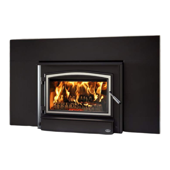
OSBURN 3500-I
(OB03510 Model)
Safety tested according to
ULC S628, UL 1482 and
UL 737 by an accredited
laboratory.
US Environmental Protection
Agency phase II certified
wood insert compliant with
2020 cord wood standard.
EPA
< ≤
2.5
g/h
2020-07-15
46180A
Advertisement
Table of Contents

Subscribe to Our Youtube Channel
Related Manuals for Osburn 3500-I


Summary of Contents for Osburn 3500-I
- Page 1 Installation and Operation Manual OSBURN 3500-I (OB03510 Model) Safety tested according to ULC S628, UL 1482 and UL 737 by an accredited laboratory. US Environmental Protection Agency phase II certified wood insert compliant with 2020 cord wood standard. < ≤...
- Page 3 It is also highly recommended to register the warranty online at https://www.osburn-mfg.com/en/warranty/warranty-registration/ Registering the warranty will help to quickly find the information needed on the unit. Installation and Operation Manual - Osburn 3500-I Page 3...
-
Page 4: Table Of Contents
PART B - INSTALLATION ......................29 7. Masonry Fireplace Requirements ..................29 7.1 Fireplace and Chimney Condition ..................29 7.2 Chimney Caps .......................29 7.3 Adjacent Combustibles ....................29 7.4 Opening Size .........................29 7.5 Masonry Fireplace Throat Damper ..................29 Page 4 Installation and Operation Manual - Osburn 3500-I... - Page 5 Appendix 6: Air Tubes and Baffle Installation ................48 Appendix 7: Removal Instructions .................... 50 Appendix 8: Exploded Diagram and Parts List ................ 51 Osburn Limited Lifetime Warranty .................... 54 Dealer: Installer: Phone Number: Serial Number: Installation and Operation Manual - Osburn 3500-I Page 5...
- Page 6 CERTIFICATION PLATE Page 6 Installation and Operation Manual - Osburn 3500-I...
-
Page 7: Part A - Operation And Maintenance
This product can expose you to chemicals including carbon monoxide, which is known to the State of California to cause cancer, birth defects or other reproductive harm. For more information go to www.P65warnings.ca.gov/ Installation and Operation Manual - Osburn 3500-I Page 7... -
Page 8: General Information
This appliance is officially tested and certified by an independent agency Tested and certified in compliance with CFR 40 part 60, subpart AAA, section 60.534(a)(1(ii) and ASTM E3053-17 based on the ATM send by EPA on October 12th, 2017. Carbon monoxide. Page 8 Installation and Operation Manual - Osburn 3500-I... -
Page 9: Specifications
Z240 MH standard. Tested and certified in compliance with CFR 40 part 60, subpart AAA, section 60.534(a)(1(ii) and ASTM E3053-17 based on the ATM send by EPA on October 12th, 2017. Installation and Operation Manual - Osburn 3500-I Page 9... -
Page 10: Dimensions
21 1/4" 48mm 540mm 11 3/4" 298mm 19" 482mm 9 1/8" 232mm 23 1/8" 586mm 27 5/8" 24 1/8" 613mm 703mm 29" 735mm Front View Side View - Maximum Insert Projection Page 10 Installation and Operation Manual - Osburn 3500-I... - Page 11 10 5/8" 269mm 19" 483mm Door Opening 3/8" 10mm 3/16" 12 7/8" 326mm 22 7/8" 20 1/8" 581mm 510mm Front View - Combustion Chamber Side View - Combustion Chamber Installation and Operation Manual - Osburn 3500-I Page 11...
-
Page 12: Materials
The space where the most time is spent will be warmest, while bedrooms and basement (if there is one) will stay cooler. In this way, less wood is burned than with other forms of heating. Page 12 Installation and Operation Manual - Osburn 3500-I... -
Page 13: Emissions And Efficiency
• Railroad ties or pressure-treated wood; starting a fire in an affected wood heater. Burning these materials may result in release of toxic fumes or render the heater ineffective and cause smoke. Installation and Operation Manual - Osburn 3500-I Page 13... -
Page 14: Tree Species
Do not burn compressed logs made of wax impregnated sawdust or logs with any chemical additives. Follow the manufacturer’s instructions and warnings. Page 14 Installation and Operation Manual - Osburn 3500-I... -
Page 15: Drying Time
− Dry wood is much lighter in weight than wet wood, − The face of a fresh cut feels warm and dry; − The moisture content read by a moisture meter is between 15% to 20%. Installation and Operation Manual - Osburn 3500-I Page 15... -
Page 16: Operating The Insert
• Install the faceplate (See «Appendix 4: Faceplate And Trims Installation»). The following step is optional : • Install the fresh air intake (See «Appendix 3: Fresh Air Intake Kit Installation»). Page 16 Installation and Operation Manual - Osburn 3500-I... -
Page 17: Blower
OPERATING THE INSERT WITH A FIRE SCREEN INCREASES POSSIBILITIES OF GENERATING CARBON MONOXIDE. CARBON MONOXIDE IS AN ODOURLESS GAS THAT IS HIGHLY TOXIC WHICH CAN CAUSE DEATH AT HIGH CONCENTRATION IN AIR. Installation and Operation Manual - Osburn 3500-I Page 17... -
Page 18: Burning Wood Efficiently
It is possible to use ragged paper but it may not hold in place since it tends to roll while it is burning. The best is to wrap a sheet on itself, grab the ends of the roll and make a knot. Page 18 Installation and Operation Manual - Osburn 3500-I... -
Page 19: Combustion Cycles
This is especially true if the chimney is on the outside wall of the house. If the door must be opened while the fire is flaming, fully open air control for a few minutes then open the door slowly. Installation and Operation Manual - Osburn 3500-I Page 19... -
Page 20: Rekindling A Fire
No other waste should be placed in this container. NEVER STORE ASHES INDOORS OR IN A NON-METALLIC CONTAINER OR ON A WOODEN DECK. CENDRES ASHES Page 20 Installation and Operation Manual - Osburn 3500-I... -
Page 21: Air Intake Control
Before reducing the air intake, the load will have to burn at full heat for long enough for charring the surface of the logs. The flame must be bright before letting the fire burn by itself. Installation and Operation Manual - Osburn 3500-I Page 21... - Page 22 East-west loads allow a limited amount of wood since too many logs could cause them to fall on the glass. East-west loads, placed in a compact way, take a long time before breaking down. They are excellent for low-intensity, long-lasting fires in relatively mild weather. Page 22 Installation and Operation Manual - Osburn 3500-I...
-
Page 23: Maintenance
The goal should be having a clear glass with no brown stains. If brown stains appear regularly on the glass, something about the fuel or the operating procedure needs to be changed. Installation and Operation Manual - Osburn 3500-I Page 23... - Page 24 Peel off more of the backing and rotate the glass. The gasket must not be stretched during installation. Page 24 Installation and Operation Manual - Osburn 3500-I...
-
Page 25: Door
Remove the split pin by pulling and turning it using pliers. Turn the handle one counterclockwise turn to increase pressure. Reinstall the split pin with a small hammer. Removing the split pin Installing the split pin Installation and Operation Manual - Osburn 3500-I Page 25... - Page 26 3/32” Allen key to free the adjustable hinge rods. 3/32" Page 26 Installation and Operation Manual - Osburn 3500-I Using a flat screwdriver, turn the adjustable hinge rods in the direction shown to adjust the doors. Ti...
-
Page 27: Exhaust System
If creosote has accumulated (⅛" [3mm] or more it should be removed to reduce the risk of a chimney fire. Installation and Operation Manual - Osburn 3500-I Page 27... - Page 28 Do not use the appliance again until the insert and its chimney have been inspected by a qualified chimney sweep or a fire department inspector. Page 28 Installation and Operation Manual - Osburn 3500-I...
-
Page 29: Part B - Installation
If it is removed from the masonry hearth, the notice plate 27009 must be installed in a visible place, inside the masonry hearth. The plate can be found in the owner’s manual kit. Installation and Operation Manual - Osburn 3500-I Page 29... -
Page 30: Safety Information And Standards
5 of this manual. It will be needed to identify the version of the appliance in the event replacement parts or technical assistance is required. Page 30 Installation and Operation Manual - Osburn 3500-I... -
Page 31: Clearances To Combustible Material
(406 mm USA) and at least 18" (457 mm Canada) without an R value. If the hearth elevation is lower than 6" (152 mm), the non-combustible (B) floor protection in front of the insert should have an R value equal or greater than 2.00 and shall extend 27" (686 mm) in front of the unit. Installation and Operation Manual - Osburn 3500-I Page 31... - Page 32 R-value, must extend at least 16" (406 mm in USA) or 18" (457 mm in Canada) in front of the unit (B). Refer to «Additional Floor Protection - Raised Installation». Page 32 Installation and Operation Manual - Osburn 3500-I...
- Page 33 R value = Thickness/K = 1/0.75 = 1.33 Information as reported by manufacturers and other resources Horizontal still air can’t be «stack» to accumulate R-values; each layer must be separated with another non-combustible material. Installation and Operation Manual - Osburn 3500-I Page 33...
-
Page 34: Minimum Masonry Opening And Clearances To Combustibles
31" (787 mm) 18 3/8" (457 mm) If a fresh air intake is required, it is recommended to add at least 4" to the width of the minimum opening of the hearth. Page 34 Installation and Operation Manual - Osburn 3500-I... -
Page 35: The Venting System
Otherwise, the diameter of the flue should be 6". The reduction of the liner diameter to less than 6" should only be done if the total height of the masonry chimney is greater than 20 feet. Installation and Operation Manual - Osburn 3500-I Page 35... -
Page 36: Chimney Liner Installation
The long end of the brackets must be attached to the insert. Insert the chimney liner into the flue collar of the unit and secure the liner to the brackets with three self-tapping screws (not included). Securing the brackets Page 36 Installation and Operation Manual - Osburn 3500-I... - Page 37 The long end of the brackets must be attached to the insert. Then, follow the instructions in the manual provided with the liner offset adapter kit. Securing the brackets Offset liner adaptor Installation and Operation Manual - Osburn 3500-I Page 37...
-
Page 38: Minimum Chimney Height
Even the finest insert will not work well when connected to this chimney. Chimney location in the house Page 38 Installation and Operation Manual - Osburn 3500-I... -
Page 39: Supply Of Combustion Air
Check the outdoor air duct for soot deposits when the full system is cleaned and inspected at least once each year. Installation and Operation Manual - Osburn 3500-I Page 39... -
Page 40: Appendix 1: Blower And Ash Lip Installation
Install the ash lip (A) on the insert with three screws (B). Center the blower on the ash lip and push it against the firebox. Then push it until it clips. Page 40 Installation and Operation Manual - Osburn 3500-I... -
Page 41: Appendix 2: Door Overlay Installation
Position the overlay (C) on the door frame and secure it in place from behind using the screws (D). To ease the installation, do not tighten the screws until they are all installed. Note: It is not necessary to remove the glass to install the overlay. Installation and Operation Manual - Osburn 3500-I Page 41... -
Page 42: Appendix 3: Fresh Air Intake Kit Installation
(F) using the other pipe clamp (D). The outside wall termination (F) must be installed outside of the home. he pipe must be HVAC type, insulated, and must comply with ULC S110 and/or UL 181, Class 0 or Class 1. Page 42 Installation and Operation Manual - Osburn 3500-I... -
Page 43: Appendix 4: Faceplate And Trims Installation
Line up the holes of the upper faceplate panel (A) with the holes of the side panels (B) and (C). Secure them together using four bolts (D) and nuts (E) provided. Installation and Operation Manual - Osburn 3500-I Page 43... - Page 44 (L) down over the faceplate. between the inner edge of the trim and the front of the faceplate. Page 44 Installation and Operation Manual - Osburn 3500-I...
- Page 45 Align the holes in the faceplate extension (M) with the holes in each faceplate side panels. DETAIL A Secure both assemblies together using 6 bolts (N) and nuts (O) provided. Installation and Operation Manual - Osburn 3500-I Page 45...
- Page 46 11. Once the faceplate is in place, secure the assembly by tightening nuts (P) using a 7/16" (11 mm) open end wrench. Page 46 Installation and Operation Manual - Osburn 3500-I...
-
Page 47: Appendix 5: Optional Fire Screen Installation
Lift the fire screen upwards and push the bottom part towards the insert then let the fire screen rest on the bottom of the door opening. Warning: Never leave the insert unattended while in use with the fire screen. Installation and Operation Manual - Osburn 3500-I Page 47... -
Page 48: Appendix 6: Air Tubes And Baffle Installation
Install the baffle. Repeat steps 1 and 2 for the three other tubes. To remove the tubes use the above steps in reverse order. Page 48 Installation and Operation Manual - Osburn 3500-I... - Page 49 Note that secondary air tubes (A) can be replaced without removing the baffle board (B) and that all tubes are identical. Installation and Operation Manual - Osburn 3500-I Page 49...
-
Page 50: Appendix 7: Removal Instructions
Remove faceplate (B) by pulling on it. Remove the blower assembly (A). Remove the three screws securing the pipe connector (D). Unscrew the bolts securing the insert to the floor on each side of the unit (E). Page 50 Installation and Operation Manual - Osburn 3500-I... -
Page 51: Appendix 8: Exploded Diagram And Parts List
APPENDIx 8: ExPLODED DIAGRAM AND PARTS LIST DETAIL B DETAIL C Installation and Operation Manual - Osburn 3500-I Page 51... - Page 52 2" X 9" 1 1/4" REFRACTORY BRICK HD PL36910 4 1/2» X 7 1/4» X 1 1/4» REFRACTORY BRICK HD PL70864 SECONDARY AIR TUBE 21565 C-CAST 3.5 SERIE BAFFLE 22" X 14" X 1 1/4" Page 52 Installation and Operation Manual - Osburn 3500-I...
- Page 53 OSBURN 3500 ONSERT INSTRUCTION MANUAL KIT 21564 C-CAST 3.5 SERIE INSULATION TOP PL34052 LINER FIXATION BRACKET AC01298 5"Ø FRESH AIR INTAKE KIT AC05959 METALLIC BLACK STOVE PAINT - 342 g (12oz) AEROSOL Installation and Operation Manual - Osburn 3500-I Page 53...
-
Page 54: Osburn Limited Lifetime Warranty
Shall your unit or a component be defective, contact immediately your OSBURN dealer. To accelerate processing of your warranty claim, make sure to have on hand the following information when calling: •... - Page 56 Resale is strictly prohibited. The manufacturer may update St-Augustin-de-Desmaures (Québec) Canada this document from time to time and cannot be responsible G3A 2H3 for problems, injuries, or damages arising out of the use 418-908-8002 of information contained in any document obtained from www.osburn-mfg.com/en unauthorized sources. tech@sbi-international.com...
Need help?
Do you have a question about the 3500-I and is the answer not in the manual?
Questions and answers