
Related Manuals for DPS Telecom TempDefender G2


Summary of Contents for DPS Telecom TempDefender G2
- Page 1 TempDefender G2 USER MANUAL D-PK-TDFG2 Visit our website at www.dpstelecom.com for the latest PDF manual and FAQs. November 19, 2020 D-UM-TDFG2 Firmware Version 2.0A...
- Page 2 Notice The material in this manual is for information purposes and is subject to change without notice. DPS Telecom shall not be liable for errors contained herein or consequential damages in connection with the furnishing, performance, or use of this...
-
Page 3: Table Of Contents
Contents Visit our w ebsite at w w w .dpstelecom .com for the latest PDF m anual and FAQs TempDefender G2 Overview Specifications Shipping List Optional Shipping Items - Available by Request Installation Tools Needed Mounting Power Connection Hardware Options... - Page 4 11.10.3 3 Alarm Module 11.11 Ping Targets 11.11.1 User Analogs 11.12 Modbus (Optional Feature) 11.12.1 Modbus Devices 11.12.2 Modbus Registers 11.13 System Alarms 11.14 Timers 11.15 Date and Time Monitoring via the Web Browser 12.1 Welcome 12.2 Standing Alarms 12.3 Alarms 12.4 Derived Alarms...
- Page 5 17.2 SNMP FAQs Technical Support End User License Agreement...
-
Page 7: Tempdefender G2 Overview
Don’t wait until the day your AC unit fails and your server closet overheats to start protecting your gear. This small, 1RU device alerts you of changing conditions 24 hours a day, 7 days a week, either to your cell or SNMP manager. The TempDefender G2 is the cost-effective way to stay proactive in your monitoring. - Page 8 In addition to its 8 discrete input points, the TempDefender G2 has 3 control relays, all form A, user defined NO/NC with short, 8 analogs, and dwire. The control relays allow network administrators to respond remotely to threats to system integrity.
-
Page 9: Specifications
Specifications Hardware Dimensions: 17.026" W x 1.720" H x 5.136" D Mounting: 19” or 23” Rack Weight: 3.5 lbs (1.56 kg) Discrete Alarm Inputs: 8 (reversible) Discrete Alarm Length: 000Ft. (00m) per Alarm Power Input: -48VDC (-36 to -72 VDC) (Optional) -24VDC Analogs: 8 (optional - 6 user, 1 power, 1 temp/pwr... -
Page 10: Shipping List
Shipping List Please make sure all of the following items are included with your TempDefender G2. If parts are missing, or if you ever need to order new parts, please refer to the part numbers listed and call DPS Telecom at 1-800-622-3314. -
Page 11: Optional Shipping Items - Available By Request
Two Standard Rack Screws Pads 1-000-12500-06 2-015-00030-00 14ft. Ethernet Cable D-PR-932-10B-14 Optional Shipping Items - Available by Request Small WAGO connector 2-802-01020-00... -
Page 12: Installation
The TempDefender G2 can be flush or rear-mounted The TempDefender G2 mounts in a 19" rack or a 23" rack using the provided rack ears for each size. Two rack ear locations are provided. Attach the appropriate rack ears in the flush-mount or rear-mount locations shown in Figure 6.2.1. -
Page 13: Power Connection
Power Connection The TempDefender G2 uses single or dual (Optional) power inputs, powered through two barrier plug power connectors. TempDefender G2 Power Terminals and Fuses To connect the TempDefender G2 to a power supply: 1. Locate the metal grounding lug next to the symbol . -
Page 14: Hardware Options
TempDefender G2 with integrated 10/100Base T Ethernet switch You can order your TempDefender G2 with an optional integrated Ethernet switch, which provides seven regular Ethernet ports. The integrated switch is powered by the same power as the TempDefender, which provides more secure, more robust operation than switches that run off commercial power. -
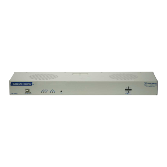
Page 15: Temp Defender G2 Front Panel
Temp Defender G2 Front Panel TempDefender G2 Front Panel... - Page 16 Status Description Solid Green Power Supply A OK No Voltage (or) Power Leads Reversed Solid Green Power Supply B OK B (Optional) No Voltage (or) Power Leads Reversed Solid Red Blown Fuse Fuse OK Flashing Green Application Running Status Flashing Red Bootloader Running Flashing Red New Alarm...
-
Page 17: Temp Defender G2 Back Panel
Quick Start: How to Connect to the Temp Defender G2 Most TempDefender G2 users find it easiest to give the unit an IP address, subnet and gateway through the front craft port (TTY interface) to start. Once these settings are saved and you reboot the unit, you can access it over LAN to do the rest of your databasing via the Web Browser interface. -
Page 18: Via Craft Port (Using Tty Interface)
TempDefender G2 Craft Port Use the front panel craft port to connect the TempDefender G2 IT to a PC for onsite unit configuration. To use the craft port, connect the included DB9 download cable from your PC's COM port to the craft port. - Page 19 5. Insert TempDefender G2 Resource Disc (CD) into your PC. 6. Click "Browse" 7. Select the "Driver" folder of your TempDefender G2 Resource Disc Disc (CD) and click "OK" The following message will confirm installation of a new "USB Communications Port"...
- Page 20 8. Click "Finish" to close the Wizard. Now that the driver has been installed, a new COM port is being emulated on your PC. Before using hyperterminal, you must confirm the identity of that new COM port (COM1, COM2, COM3...) in the Windows Device Manager.
- Page 21 10.Click "Device Manager" in the left pane. 11.Expand the "Ports (COM & LPT)" section in the right pane. Look for "USB Communications Port (COMx)". Note the number of the COM port ("COM3" in the example above). 12.Click on the Start menu > select Programs > Accessories > Communications > HyperTerminal. 13.
- Page 22 Once connected, you will see a blank, white HyperTerminal screen. Press Enter to activate the configuration menu. 17. The TempDefender G2's main menu will appear. 18. ESC to the main menu. When asked if you'd like Type C for C)onfig, then E for E)thernet. Configure the to save your changes, type Y for Y)es.
- Page 23 instructions on setting up your LAN connection.
- Page 24 Now you're ready to do the rest of your configuration via LAN. Plug your LAN cable into the TempDefender G2 and see "Logging On to the TempDefender G2" to continue databasing using the Web Browser.
-
Page 25: Tty Interface
TTY Interface The TTY interface is the TempDefender G2's built-in interface for basic configuration. From the TTY interface, you can: · Edit the IPA, subnet, and gateway · Set DCP info for T/Mon polling · Configure primary port · Ping other devices on the network ·... -
Page 26: Configure Serial Port Via Tty
Configure Serial Port via TTY Serial port configuration 1. To enter configuration setting for the Serial Port, login to the TTY interface and press C)onfig > s(E)rial. 2. Press the hot keys to toggle through the following options. (* Indicates default settings:) NOTE: Default settings may not reflect the primary interface that shipped in the unit. -
Page 27: How To Send Email Notifications
10.1 How to Send Email Notifications 1. Click on the Notifications button in the Provisioning menu. You can setup as many as 8 different notifications. Begin the setup "wizard" by clicking Edit for a notification number. In this example, we'll setup Notification 1 to send emails. - Page 28 4. At the Schedule screen, you'll select the exact days/times you want to receive email notifications. You can set 2 schedules per notification. For example, you may want to receive notifications at certain times during the week, and at different hours on the weekend. Use the check boxes to select the days of the week, and select the time from the drop down menus.
-
Page 29: How To Send Snmp Traps
10.2 How to Send SNMP Traps 1. Click on the SNMP button in the Provisioning menu. Enter the SNMP GET and SNMP SET community strings for your network, then click Save. The typical SNMP SET and GET community strings for network devices is "public". - Page 30 4. At the SNMP Notification screen, you'll enter your network's SNMP settings. Enter the IP address of your SNMP Trap Server. Enter the Trap Port Number (usually 162) and the Trap Community password. Click Save and Next. 5. At the Schedule screen, you'll select the exact days/times you want to receive SNMP notifications. You can set 2 schedules per notification.
-
Page 31: Provisioning Menu Field Descriptions
Provisioning Menu Field Descriptions TempDefender G2 configuration is performed from the Provisioning menus, the menu options in green on the left- side of the web interface. The following pages provide a brief description of the options available in each menu. -
Page 32: System
11.1 System From the Provisioning > System menu, you will configure and edit the global system, call, T/Mon and control settings for the TempDefender G2. The Provisioning > System menu... - Page 33 Name A name for this TempDefender G2 unit. (Optional field) Location The location of this TempDefender G2 unit. (Optional field) Contact telephone number for the person responsible for this TempDefender G2 unit. Contact (Optional field) Disable Telnet (Only on high-security firmware versions) Check to disable Telnet connections to the (not pictured) TempDefender G2.
-
Page 34: History Log Format And Operation
11.1.1 History Log Format and Operation GET parameters can be used with the history.csv or the eventlog.csv request to filter the returned data. When no GET parameters are supplied, all data will be returned in CSV format. To add GET parameters: qRight-click the history.csv link on the Provisioning >... -
Page 35: User Profiles
User Profiles Clicking User Profiles gives you access to modify the default username and password, and to edit the administrator profile and create up to 9 additional unique user profiles, each with different access rights to the TempDefender G2's web interface. - Page 36 To create or edit any of the 10 user profiles (including the Admin), click the Edit button. From there, you can change all configurable settings for a user profile. User Profile Suspend this Profile If this box is checked, the profile will not be able to access the TempDefender G2. Username Enter a username or a user description Password Enter a unique user password Note: All passwords are AES 128 encrypted.
-
Page 37: Ethernet
Unit IP IP address of the TempDefender G2. A road sign to the TempDefender G2, telling it whether your packets should stay on your Subnet Mask local network or be forwarded somewhere else on a wide-area network. An important parameter if you are connected to a wide-area network. It tells the Gateway TempDefender G2 which machine is the gateway out of your local network. -
Page 38: Serial Port
Serial Port The Provisioning > Serial Port menu allows you to change settings depending on the port type of your TempDefender G2. From this menu, you can select a mode of operation and enable reach-through serial port functionality. The Provisioning > Serial Ports menu... -
Page 39: Snmp
Community name for SNMP requests. Set Community Community name for SNMP SET requests. This field defines how the TempDefender G2 unit may be accessed via SNMP. This can be set to the following: Read and Write · Access Disabled- Restricts all access to unit via SNMP Access ·... -
Page 40: Notifications
11.6 Notifications From the initial Provisioning > Notifications menu, you will see which of the 8 notifications are enabled, their server, and schedule. Click on the Edit link for one of the notifications to begin configuration. Once you've chosen which notification you want to setup, check the Enable Notification to turn it "on." Then choose a notification method, either email, SNMP, voice call, or TRIP Dialup (T/Mon). - Page 41 Displays the email address (defined in the Edit menu > System) that the "From" E-mail Address TempDefender G2 will send emails from. Not editable from this screen. The email address of the person responsible for this TempDefender G2, who "To" E-mail Address will receive email alarm notifications.
-
Page 42: Schedule
Indicate whether you would like to send SNMP v1, v2c or v3 traps. 11.6.2 Schedule The notifications scheduling menu is where you will tell the TempDefender G2 exactly which days and times you want to receive alarm notifications. You set 2 different schedules for each. The Schedule creation screen... -
Page 43: Alarms
11.7 Alarms Discrete alarms are configured from the Provisioning > Alarms menu. Descriptions for the alarm points, polarity (normal or reversed) and notification type(s) are defined from this menu. You also have the option to use Basic or Advanced configuration methods, explained in this section. The Provisioning >... -
Page 44: Derived Alarms
11.8 Derived Alarms Basic Controls Configuration ID number for the derived alarm. Description User-definable description for the derived alarm. Rev. Reverse the polarity of the alarm in the software by checking this box. Check which notification device(s), 1 through 8, you want to send alarm notifications Notification Devices for the derived alarm. -
Page 45: Controls
11.9 Controls The TempDefender G2's 3 control relays can be configured in the Provisioning > Controls menu. You can enter your own description for these relays and designate them to a notification device(s). The Provisioning > Controls screen Basic Controls Configuration ID number for the control relay. -
Page 46: Sensors
The TempDefender G2 supports up to 32 daisy-chained D-Wire sensors via its D-Wire input. Sensors connected to the TempDefender G2 will appear on the web interface. The background color of the ROM field informs the user of the sensor's configuration state. - Page 47 The unit will refresh the sensor ID on that channel. Description User-definable description for the sensor channel. Parse Checks to see if the Description field contains a valid equation. Check which notification device(s), 1 through 8, you want to send alarm notifications Notification Devices for that alarm point.
-
Page 48: Hvac Monitoring
11.10.1 HVAC Monitoring Temperature / Air Flow sensors can be used to monitor HVAC health. Enabling HVAC Monitoring on this sensor adds the extra fields below. Sensor with HVAC Monitoring enabled. - Page 49 HVAC Monitor Mode The time the HVAC has between starting and reaching operational Air Flow and Vent Air Flow Qual Time Temperature Mate The ROM ID for the temperate sensor in the same package as the Air Flow sensor Set MjU to -20 Set MnU to -10 Set MnO to a small, positive value.
- Page 50 Setting up a Temperature/Air Flow Sensor as an HVAC Monitor: 1. In Provisioning->Sensors, open the Details menu of the airflow sensor that is going to be used as the HVAC Monitor. 2. Check the 'HVAC Monitor' checkbox 3. Save and Write changes. This will expand menu to display HVAC Monitor Settings. 4.
-
Page 51: Script Sensors
11.10.2 Script Sensors A Script Sensor can be setup by entering a script type in the sensor ID field. The following types are currently supported: ~count - The equation will be evaluated continuously. If the evaluation changes at any point, the sensor's value increases by an increment of 1. - Page 52 How equations are evaluated: Calculations are performed from left-to-right until the end of the equation is reached. As the equation is parsed, each token's value is pushed onto a stack until an operator is found. When an operator is found, the previous 2 values are popped from the stack and are used to perform the operation (the first item popped is the SECOND operand).
-
Page 53: Alarm Module
11.10.3 3 Alarm Module You can now assign derived alarms to the alarm points of a D-Wire 3 Alarm Module. Just like any other D-Wire sensor, you can plug the 3Alarm Module into the D-Wire port of your device, or you can add it to your other daisy chained sensors. -
Page 54: Ping Targets
11.11 Ping Targets The Provisioning > Ping Targets menu allows you to configure the Description, IP Address, and Notification Devices for each of your ping targets. The Provisioning > Ping Targets menu Provisioning Ping Targets ID number for the ping target. Enab Check this box to enable the ping target. -
Page 55: User Analogs
11.11.1 User Analogs The TempDefender G2's sixteen multi-purpose analog inputs measure continuous ranges of voltage or current. Analog alarms are typically used to monitor battery voltage, charging current, temperature, humidity, wind speed, or other continuously changing conditions. To configure a user analog, simply fill in your description, thresholds, and other fields listed in the table below, then click Save. - Page 56 Push to Talk: Enable Checking this box enables Push-to-Talk feature for this analog. Discrete Input Assign the alarm point associated with this analog. Length of time, in milliseconds, that an alarm point must be set before before an analog Qual. Time (ms) can post.
-
Page 57: Modbus (Optional Feature)
Modbus (Optional Feature) The TempDefender G2 is able to support the Modbus protocol. This is an optional capability that can be acquired with a special feature code through the sales department. If you are interested in this capability, call 559-454-1600 or email sales@dpstele.com. - Page 58 Global Settings Modbus Poll Delay Delay between Modbus polls in milliseconds. Modbus Poll Time duration before the Modbus repsonse time fails in seconds. Timeout Send Notification This option is used to send a notification whenever a Modbus register is polled. of every register If the poll delay is too low this may cause some notifications to be lost.
-
Page 59: Modbus Registers
11.12.2 Modbus Registers Provisioning > Modbus Registers... - Page 60 Basic Configuration Modbus register ID Modbus Device Modbus device settings used when polling. Description User0definable description for the Modbus register. Notifications Check which notification device(s), 1 through 8, you want to send alarm notifications for that Modbus register. Details Function Code Modbus function code to use when polling device Event Qualification Qual.
-
Page 61: System Alarms
11.13 System Alarms See "Display Mapping" in the Reference Section for a complete description of system alarms. The Provisioning > System Alarms menu Editing System Alarms Pnt (Point) The system alarm point number Description Non-editable description for this System (housekeeping) Alarm. Silence Check this box to choose to silence this alarm. -
Page 62: Timers
11.14 Timers Enter the amount of time in seconds (sec) or minutes (m), in each value field and click Save. The Provisioning > Timers menu... -
Page 63: Date And Time
Select your time zone from the drop-down menu. Adjust Clock for Daylight Savings Time (DST) Enable DST Check this box to have the TempDefender G2 observe Daylight Savings. Start Day Select the month, weekday, and time when Daylight Savings will begin. -
Page 64: Monitoring Via The Web Browser
Mobile" in the page footer. NOTE: The current device version is located in the top right corner of the page.Clicking the version number will open a new tab to the DPS firmware download page for the TempDefender G2. Welcome screen on a desk top. - Page 65 Welcome screen on a mobile...
-
Page 66: Standing Alarms
12.2 Standing Alarms The Standing Alarms page provides a general overview of any active alarms that may require immediate action. For example: high temperature, door open, or even a derived alarm. This page shows alarm types such as base alarms, controls, sensor and analog thresholds. For base and system alarms a timer will appear for each alarm, showing how long the alarm has been active. -
Page 67: Alarms
12.3 Alarms This selection provides the status of the base alarms by indicating if an alarm has been triggered. Under the State column, the status will appear in red if an alarm has been activated. The status will be displayed in green when the alarm condition is not present. -
Page 68: Derived Alarms
12.4 Derived Alarms From the Monitor > Derived Alarms window, you can see what state each of your Derived Alarms is in. -
Page 69: Controls
3. To issue the control, click on a command (OPR - operate, RLS - release, or MOM - momentary) View and operate control relays from the Monitor > Controls menu Control Relay Operation ID number for the control relay. Description for the TempDefender G2's control relay defined in the Provisioning > Description Controls menu. State Status of the control relay. -
Page 70: Sensors
12.6 Sensors This selection provides the status of the system's analog channels by indicating if an alarm has been triggered. The Monitor > Sensors screen provides a description of each analog channel, the current reading, the units being read, and alarm conditions (major under, minor under, major over, minor over) according to your temperature settings. If configured under Provisioning >... -
Page 71: Hvac Monitoring
12.6.1 HVAC Monitoring When using a Temp/Air Flow sensor for HVAC Monitoring, the HVAC Air Flow sensor monitor section will display 4 thresholds instead of one. Alarm Descriptions HVAC Air Flow This alarm will tell you if there is air flow coming from the HVAC unit. This alarm will trigger if the temperature is not within Heating or Cooling range by the (HVFail) HVAC Failed time Air Flow Qual Time expires, or if during operation Temperature goes out of Heating... -
Page 72: User Analogs
12.7 User Analogs On the Monitor > User Analogs menu, you can monitor all analog inputs. The most recent measurement will be shown, and any alarm thresholds crossed will be shown in shown in either orange for minor alarms or red for major alarms. Fig. -
Page 73: Ping Targets
12.8 Ping Targets Ping Targets can be viewed by going to Monitor > Ping Targets. Here you can view the state (either Clear or Alarm) for each of your configured Ping Targets. View the status of Ping Targets from the Monitor > Ping Targets menu. -
Page 74: Modbus (Optional Feature)
Modbus (Optional Feature) The TempDefender G2 is able to support the Modbus protocol. This is an optional capability that can be acquired with a special feature code through the sales department. If you are interested in this capability, call 559-454-1600 or email sales@dpstele.com. -
Page 75: System Alarms
12.10 System Alarms System alarms are not-editable, housekeeping alarms that are programmed into TempDefender G2. The Monitor > System Alarms screen provides the status of the system alarms by indicating if an alarm has been triggered. Under the State column, the status will appear in red if an alarm has been activated. The status will be displayed in green when the alarm condition is not present. -
Page 76: Graph
12.11 Graph The Graph section of the monitor menu lets you build a graph of past analog and sensor measurements, which gives you a visual indication of data over time and points out trending values. To create your Graph, specify the Channel (Analogs 1-8 or Sensors 1-32), Group Interval (1-120 minutes, hours, days, or weeks), the Group Function (Average, Min, Max), and Start &... -
Page 77: Device Access Descriptions
The Device Access options, listed in pink on the left side of the web interface, provide options for generating reports, updating the TempDefender G2's firmware, and rebooting the unit. Click any of the options under Device Access to perform the desired action. -
Page 78: Backup Configuration
Backup Configuration With the TempDefender G2 you can backup your current configuration from the Web Interface. These configuration files can then be uploaded later, or uploaded to other TempDefender G2 units. The Back up Config tab is located in the Device Access menu shown above. -
Page 79: Firmware Upgrade
Firmware Upgrade To access the Firmware Load screen, click on the Provisioning > System menu. At the bottom of this screen, click the Restore Configuration link located in the System Controls section. To upload firmware, click on Upload on the top right corner of the web interface At the Firmware Load screen, simply browse for the firmware update you've downloaded from www.dpstele.com and click Load. -
Page 80: Reference Section
Reference Section 16.1 Display Mapping Description Port Address Point Discrete Alarms 1-8 Undefined 9-16 Controls 1-3 17-19 Undefined 20-32 Default Configuration DIP Switch Configuration MAC Address Not Set IP Address Not Set LAN Hardware Error SNMP Processing Error SNMP community error Display 1 LAN TX packet drop Notification Failed 1-8... - Page 81 Value 49-64 Analog 5 Minor Under Analog 5 Minor Over Analog 5 Major Under Analog 5 Major Over Reserved (CTRL) 9-16 Value 17-32 Display 5 Analog 6 Minor Under Analog 6 Minor Over Analog 6 Major Under Analog 6 Major Over Reserved (CTRL) 41-48 Value...
- Page 82 Description Port Address Point Analog 7 Minor Under Analog 7 Minor Over Analog 7 Major Under Analog 7 Major Over Reserved (CTRL) 9-16 Value 17-32 Display 6 Analog 8 Minor Under Analog 8 Minor Over Analog 8 Major Under Analog 8 Major Over Reserved (CTRL) 41-48 Value...
- Page 83 Description Port Address Point Digital Sensor 5 - Minor Under Digital Sensor 5 - Minor Over Digital Sensor 5 - Major Under Digital Sensor 5 - Major Over Digital Sensor 5 - Not Detected Control 9-16 Value 17-32 Display 9 Digital Sensor 6 - Minor Under Digital Sensor 6 - Minor Over Digital Sensor 6 - Major Under...
- Page 84 Description Port Address Point Digital Sensor 11 - Minor Under Digital Sensor 11 - Minor Over Digital Sensor 11 - Major Under Digital Sensor 11 - Major Over Digital Sensor 11 - Not Detected Control 9-16 Value 17-32 Display 12 Digital Sensor 12 - Minor Under Digital Sensor 12 - Minor Over Digital Sensor 12 - Major Under...
- Page 85 Description Port Address Point Digital Sensor 17 - Minor Under Digital Sensor 17 - Minor Over Digital Sensor 17 - Major Under Digital Sensor 17 - Major Over Digital Sensor 17 - Not Detected Control 9-16 Value 17-32 Display 15 Digital Sensor 18 - Minor Under Digital Sensor 18 - Minor Over Digital Sensor 18 - Major Under...
- Page 86 Description Port Address Point Digital Sensor 23 - Minor Under Digital Sensor 23 - Minor Over Digital Sensor 23 - Major Under Digital Sensor 23 - Major Over Digital Sensor 23 - Not Detected Control 9-16 Value 17-32 Display 18 Digital Sensor 24 - Minor Under Digital Sensor 24 - Minor Over Digital Sensor 24 - Major Under...
-
Page 87: System Alarms
MAC Address Not Set The MAC Address is not set. 454-1600 See Section "Quick Start: How to Connect to the TempDefender G2 IP Address Not Set The IP Address is not set. via Craft Port." If not using the TempDefender over LAN, set the IP address to 255.255.255.255... - Page 88 would like to send SNMP trap defined and an SNMP trap events, or configure the event not event occurred. to trap. Community string does not Verify both community strings to SNMP Community Error match your SNMP master's make sure they match. community string.
- Page 89 TempDefender Verify that unit can ping T/Mon or configured to listen for DCP DCP Poller inactive disable if not in use. polls but has not received a poll in over 5 minutes. TempDefender Verify that unit can ping modbus configured to listed for modbus Modbus poller inactive master or disable if not in use.
-
Page 90: Derived Alarm And Control Equations
16.3 Derived Alarm and Control Equations Virtual alarms and control relays can be created from derived formulas using the following operations: _OR : Set the current operation to OR. _AN : Set the current operation to AND. _NO : Set the current operation to NOT _XR : Set the current operation to XOR. -
Page 91: Snmp Manager Functions
16.4 SNMP Manager Functions The SNMP Manager allows the user to view alarm status, set date/time, issue controls, and perform a resync. The display and tables below outline the MIB object identifiers. The table below begins with dpsRTU; however, the MIB object identifier tree has several levels above it. -
Page 92: Snmp Granular Trap Packets
The tables below provide a list of the information contained in the SNMP Trap packets sent by the TempDefender SNMP Trap managers can use one of two methods to get alarm information: 1. Granular traps (not necessary to define point descriptions for the TempDefender G2) OR 2. The SNMP manager reads the description from the Trap. -
Page 93: Modbus Register Map
16.6 Modbus Register Map Function Register (Dec) Scale Data Type Description Function 1- Read 0x0000 (0) Control 1 State Coils (Controls) 0x0001 (1) Control 2 State Return value of 0x00 0x0002 (2) Control 3 State means control is released Return value of 0x01 means control is latched 0x0000 (0) - Page 94 0x0002 (2) INT16 User Analog 2 0x0003 (3) INT16 User Analog 3 0x0004 (4) INT16 User Analog 4 0x0005 (5) INT16 User Analog 5 0x0006 (6) INT16 User Analog 6 0x0007 (7) INT16 User Analog 7 0x0008 (8) INT16 User Analog 8 0x0009 (9) INT16 D-Wire Sensor 1...
- Page 95 0x006D (109) INT16 D-Wire Sensor 1 0x006E (110) INT16 D-Wire Sensor 2 0x006F (111) INT16 D-Wire Sensor 3 0x0070 (112) INT16 D-Wire Sensor 4 0x0071 (113) INT16 D-Wire Sensor 5 0x0072 (114) INT16 D-Wire Sensor 6 0x0073 (115) INT16 D-Wire Sensor 7 0x0074 (116) INT16 D-Wire Sensor 8...
- Page 96 Function Register (Dec) Scale Data Type Description 0x00C9 (201) INT16 User Analog 1 0x00CA (202) INT16 User Analog 2 0x00CB (203) INT16 User Analog 3 0x00CC (204) INT16 User Analog 4 0x00CD (205) INT16 User Analog 5 0x00CE (206) INT16 User Analog 6 0x00CF (207) INT16...
- Page 97 0x03EA (1002) INT16 User Analog 2 0x03EB (1003) INT16 User Analog 3 0x03EC (1004) INT16 User Analog 4 0x03ED (1005) INT16 User Analog 5 0x03EE (1006) INT16 User Analog 6 0x03EF (1007) INT16 User Analog 7 0x03F0 (1008) INT16 User Analog 8 0x03F1 (1009) INT16 D-Wire Sensor 1...
- Page 98 Function Register (Dec) Scale Data Type Description 0x044D (1101) INT16 User Analog 1 0x044E (1102) INT16 User Analog 2 0x044F (1103) INT16 User Analog 3 0x0450 (1104) INT16 User Analog 4 0x0451 (1105) INT16 User Analog 5 0x0452 (1106) INT16 User Analog 6 0x0453 (1107) INT16...
- Page 99 0.01 0x04B7 (1207) INT16 User Analog 7 0.01 0x04B8 (1208) INT16 User Analog 8 0.01 0x04B9 (1209) INT16 D-Wire Sensor 1 0.01 0x04BA (1210) INT16 D-Wire Sensor 2 0.01 0x04BB (1211) INT16 D-Wire Sensor 3 0.01 0x04BC (1212) INT16 D-Wire Sensor 4 0.01 0x04BD (1213) INT16...
-
Page 100: Dnp3 Configuration / Interoperability Guide
DNP V3.0 DEVICE PROFILE DOCUMENT (Also see the DNP 3.0 Implementation Table in Section 4.6.2) Vendor Name: DPS Telecom Inc. Device Name: TempDefender G2 Highest DNP Level Supported: Device Function:... - Page 101 DNP V3.0 DEVICE PROFILE DOCUMENT (Also see the DNP 3.0 Implementation Table in Section 4.6.2) Timeouts while waiting for: Data Link Confirmation: Fixed at 2s Complete Appl. Fragment: None Application Confirm: Fixed at 10s Complete Appl. Response: None Other: Transmission Delay, 0 Sends/Executes Control Operations: WRITE BinaryOutputs: Never SELECT/OPERATE: Never...
-
Page 102: Dnp V3.0 Implementation Table
DNP V3.0 DEVICE PROFILE DOCUMENT (Also see the DNP 3.0 Implementation Table in Section 4.6.2) Sends Multi-Fragment Responses: Sequential File Transfer Support: No Append File Mode: No Custom Status Code Strings: No Permissions Field: No File Events Assigned to Class: No File Events Send Immediately: No Multiple Blocks in a Fragment: No Max Number of Files Open: 0... -
Page 103: Dnp V3.0 Point List
16.7.3 DNP V3.0 Point List The tables below identify all the default data points provided by the TempDefender G2. Obj 01 Var 01 - Single-bit Binary Inputs Obj 02 Var 02 - Binary Input Change with Time Point Index... - Page 104 136-139 Analog 2 33-36 144-147 Analog 3 152-155 Analog 4 33-36 160-163 Analog 5 168-171 Analog 6 33-36 176-179 Analog 7 184-187 Analog 8 33-36 192-199 Digital Sensor 1 200-207 Digital Sensor 2 33-40 208-215 Digital Sensor 3 216-223 Digital Sensor 4 33-40 224-231 Digital Sensor 5...
- Page 105 BinaryOutput Status Points Static Variation: Obj 10 Var 02 - BinaryOutput Status Request function codes supported: 5 (direct operate), 6 (direct operate, no ack) Supported relay output: Latch on, Latch off. Point ID Description Class Control 1 Control 1 Control 1 Analog Inputs The following table lists Analog Inputs (Object 30).
- Page 106 Analog Inputs Static Variation: Obj 30 Var 03 - 32-Bit analog w/o flag Request function codes supported: 1 (read) Point ID Description Default Unit Class Analog Channel 1 Voltage (VDC) Analog Channel 2 Voltage (VDC) Analog Channel 3 Voltage (VDC) Analog Channel 4 Voltage (VDC) Analog Channel 5...
-
Page 107: Frequently Asked Questions
Q. How do I connect my TempDefender G2 to the LAN? A. To connect your TempDefender G2 to your LAN, you need to configure the unit IP address, the subnet mask and the default gateway. A sample configuration could look like this: Unit Address: 192.168.1.100... - Page 108 A. SNMP v1, SNMPv2 and SNMPv3. Q. How do I configure the TempDefender G2 to send traps to an SNMP manager? Is there a separate MIB for the TempDefender G2? How many SNMP managers can the agent send traps to? And how do I set the IP address of the SNMP manager and the community string to be used when sending traps? A.
- Page 109 3. Have access to troubled equipment. Please be at or near your equipment when you call DPS Telecom Technical Support. This will help us solve your problem more efficiently. 4. Call during Customer Support hours.
- Page 112 DPS Telecom which arise out of or are related to the non-fulfillment of any covenant or obligation of End User in connection with this Agreement.
- Page 113 Warranty DPS Telecom warrants, to the original purchaser only, that its products a) substantially conform to DPS' published specifications and b) are substantially free from defects in material and workmanship. This warranty expires two years from the date of product delivery with respect to hardware and ninety days from the date of product delivery with respect to software.
- Page 114 Free Tech Support is Only a Click Away Need help with your alarm monitoring? DPS Information Services are ready to serve you … in your email or over the Web! www.DpsTelecom.com Free Tech Support in Your Email: The Protocol Alarm Monitoring Ezine The Protocol Alarm Monitoring Ezine is your free email tech support alert, delivered directly to your in-box every two weeks.
Need help?
Do you have a question about the TempDefender G2 and is the answer not in the manual?
Questions and answers