
Related Manuals for Belden HIRSCHMANN OCTOPUS OS3


Summary of Contents for Belden HIRSCHMANN OCTOPUS OS3
- Page 1 User Manual Installation Managed Ethernet Switch OCTOPUS OS3 Installation OCTOPUS OS3 Technical support Release 03 08/2020 https://hirschmann-support.belden.com...
- Page 2 The naming of copyrighted trademarks in this manual, even when not specially indicated, should not be taken to mean that these names may be considered as free in the sense of the trademark and tradename protection law and hence that they may be freely used by anyone. ©...
-
Page 3: Table Of Contents
Contents Important Information Safety instructions About this manual Description General device description Device name and product code Device views 1.3.1 Device variants with 24 × Ethernet ports 1.3.2 Device variants with 16 × Ethernet ports 1.3.3 Device variants with 8 × Ethernet ports 1.3.4 Device variants with Uplink ports/Bypass function 1.3.5 Port assignment Power supply... - Page 4 Installation Checking the package contents Installing and grounding the device 2.2.1 Mounting on a flat surface 2.2.2 Grounding the device Connecting the ferrites Connecting the supply voltage Connecting data cables Basic Settings Default settings First login (Password change) Monitoring the ambient air temperature Maintenance and service Disassembly Removing the device...
- Page 5 Accessories Underlying technical standards Further support Installation OCTOPUS OS3 Release 03 08/2020...
-
Page 6: Important Information
Important Information Notice: Read these instructions carefully, and look at the equipment to become familiar with the device before trying to install, operate, or maintain it. The following special messages may appear throughout this documentation or on the equipment. The message warns of potential hazards or calls attention to information that clarifies or simplifies a procedure. -
Page 7: Safety Instructions
Safety instructions WARNING UNCONTROLLED MACHINE ACTIONS To avoid uncontrolled machine actions caused by data loss, configure all the data transmission devices individually. Before you start any machine which is controlled via data transmission, be sure to complete the configuration of all data transmission devices. Failure to follow these instructions can result in death, serious injury, or equipment damage. - Page 8 Qualification requirements for personnel Only allow qualified personnel to work on the device. Qualified personnel have the following characteristics: Qualified personnel are properly trained. Training as well as practical knowledge and experience make up their qualifications. This is the prerequisite for grounding and labeling circuits, devices, and systems in accordance with current standards in safety technology.
- Page 9 use of plastic protection screws is prohibited. Protection screws and screw caps made of metal are available as an accessory. See “Accessories” on page 57. Grounding the device Grounding the device is by means of a separate ground connection on the device.
- Page 10 Requirements for connecting the supply voltage The following requirements apply without restrictions: All of the following requirements are complied with: The supply voltage corresponds to the voltage specified on the type plate of the device. The power supply conforms to overvoltage category I or II. ...
- Page 11 CE marking The labeled devices comply with the regulations contained in the following European directive(s): 2011/65/EU and 2015/863/EU (RoHS) Directive of the European Parliament and of the Council on the restriction of the use of certain hazardous substances in electrical and electronic equipment.
- Page 12 Supplier's Declaration of Conformity 47 CFR § 2.1077 Compliance Information OCTOPUS OS3 U.S. Contact Information Belden – St. Louis 1 N. Brentwood Blvd. 15th Floor St. Louis, Missouri 63105, United States Phone: 314.854.8000 This device complies with part 15 of the FCC Rules. Operation is subject...
-
Page 13: About This Manual
About this manual The “Installation” user manual contains a device description, safety instructions, a description of the display, and the other information that you need to install the device. Documentation mentioned in the “User Manual Installation” that is not supplied with your device as a printout can be found as PDF files for downloading on the Internet at: https://www.doc.hirschmann.com Installation OCTOPUS OS3... -
Page 14: Key
The symbols used in this manual have the following meanings: Listing Work step Subheading Installation OCTOPUS OS3 Release 03 08/2020... -
Page 15: Description
Description General device description The device is designed for the special requirements of industrial automation. The device meets the relevant industry standards, provides very high operational reliability, even under extreme conditions, and also long-term reliability and flexibility. The device allows you to set up switched Industrial Ethernet networks according to standard IEEE 802.3. -
Page 16: Device Name And Product Code
Device name and product code The product code is made up of characteristics with defined positions. The characteristic values stand for specific product properties. Item Characteristic Characteri Description stic value 1 ... 3 Product OCTOPUS OS3 (hyphen) Data rate 10/100 Mbit/s ports 10/100/1000 Mbit/s ports 10/100/1000 Mbit/s ports Hardware type... - Page 17 Item Characteristic Characteri Description stic value 26 ... 27 Supply voltage 2 voltage inputs for redundant power supply Rated voltage 24 V DC Rated voltage range 16.8 V DC ... 32 V DC Connection type 5-pin M12 connector 2 voltage inputs for redundant power supply Rated voltage 36 V DC ...
-
Page 18: Device Views
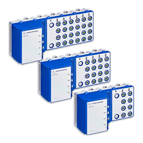
Device views 1.3.1 Device variants with 24 × Ethernet ports V.24 interface 4-pin, “A”-coded M12 socket USB interface 5-pin, “A”-coded M12 socket Signal contact 5-pin, “A”-coded M12 plug Supply voltage connection 5-pin, “K”- or “L”-coded M12 plug LED display elements for port status 24 ×... -
Page 19: Device Variants With 16 × Ethernet Ports
1.3.2 Device variants with 16 × Ethernet ports V.24 interface 4-pin, “A”-coded M12 socket USB interface 5-pin, “A”-coded M12 socket Signal contact 5-pin, “A”-coded M12 plug Supply voltage connection 5-pin, “K”- or “L”-coded M12 plug LED display elements for port status 16 ×... -
Page 20: Device Variants With 8 × Ethernet Ports
1.3.3 Device variants with 8 × Ethernet ports V.24 interface 4-pin, “A”-coded M12 socket USB interface 5-pin, “A”-coded M12 socket Signal contact 5-pin, “A”-coded M12 plug Supply voltage connection 5-pin, “K”- or “L”-coded M12 plug LED display elements for port status 8 ×... -
Page 21: Device Variants With Uplink Ports/Bypass Function
1.3.4 Device variants with Uplink ports/Bypass function First uplink port pair Port 5 and 6 Bypass functionality for device variants OS3-....R6R6... Second uplink port pair Port 7 and 8 Bypass functionality for device variants OS3-....R6R6... Table 5: Front view (using the example OCTOPUS3-40-...) In the case of a power supply failure, Uplink ports are connected with each other. -
Page 22: Port Assignment
1.3.5 Port assignment Figure 1: Port assignment: Port assignment OCTOPUS OS3 Note: The numerical sequence of the port assignment is identical for every device variant. Installation OCTOPUS OS3 Release 03 08/2020... -
Page 23: Power Supply
Note: For devices with PoE/PoE+ ports: The exact position of the PoE/PoE+ ports on the device are printed on the device. Ports with PoE/Poe+ are marked with the PoE/PoE+ logo on the bottom right side of the port. Power supply 1.4.1 Supply voltage with the characteristic value BB The supply voltage can be connected redundantly. -
Page 24: Supply Voltage With The Characteristic Value Qq
1.4.4 Supply voltage with the characteristic value QQ The supply voltage can be connected redundantly. Both inputs are uncoupled. With a non-redundant supply of the supply voltage, the device reports the loss of a supply voltage. You can prevent this message by applying the supply voltage via both inputs, or by changing the configuration in the Management. -
Page 25: Ethernet Ports
Ethernet ports You have the option to connect end devices or other segments to the ports of the device via twisted pair cables. You find information on pin assignments for making patch cables here: “Pin assignments” on page 26 10/100 Mbit/s twisted pair port ... -
Page 26: Pin Assignments
Pin assignments Supply voltage characteristic Pin Function Type value BB, HH, PP, QQ P1+ Plus terminal of supply voltage 1 5-pin M12 connector, Minus terminal of supply voltage 2 “L”-coded Minus terminal of supply voltage 1 P2+ Plus terminal of supply voltage 2 Functional earth connection Table 6: Pin assignments: Supply voltage characteristic value BB, HH, PP, QQ... - Page 27 FE port Pin Function PoE/PoE+ Type Positive V 4-pin M12 socket, “D”-coded Negative V Positive V Negative V Table 9: Pin assignments: FE port V.24 interface Pin Function Type 4-pin M12 socket, “A”-coded Table 10: Pin assignments: V.24 interface USB interface Pin Function Type 5-pin M12 socket, “A”-coded...
-
Page 28: Display Elements
Display elements After the supply voltage is set up, the Software starts and initializes the device. Afterwards, the device performs a self-test. During this process, various LEDs light up. 1.7.1 Device state These LEDs provide information about conditions which affect the operation of the whole device. - Page 29 Display Color Activity Meaning Status Device Status — none Device is starting and/or is not ready for operation. green lights up Device is ready for operation. Characteristics can be configured lights up Device is ready for operation. Device has detected at least one error in the monitoring results flashes 1 time The boot parameters used when the device...
-
Page 30: Port Status
1.7.2 Port Status Note: The port status is displayed via the left side port LED. Figure 3: Port status: location of the display elements on the device (front side of the device) LED Display Color Activity Meaning Link status — none Device detects an invalid or missing link green... -
Page 31: Poe Status
1.7.3 PoE status Note: Only PoE ports have these LEDs. The LED is on the right of the respective link state LED. Figure 4: PoE status: Location of the display elements on the device (front side of the device) LED Display Color Activity Meaning... -
Page 32: Management Interfaces 1.8.1 V.24 Interface (External Management)
Management interfaces 1.8.1 V.24 interface (external management) This interface is a 4-pin, “A”-coded M12 socket. The V.24 interface is a serial interface for the local connection of an external management station (VT100 terminal or PC with corresponding terminal emulation). This allows you to set up a connection to the Command Line Interface (CLI) and to the system monitor. -
Page 33: Input/Output Interfaces
Input/output interfaces 1.9.1 Signal contact Signal Function – – Figure 5: Signal contact: 5-pin, “A”-coded M12 plug; position on the device (front side of the device) Signal contact Not used Normally open contact Normally closed contact Not used Changeover contact The signal contact is a potential-free changeover contact. -
Page 34: Installation
Installation The devices have been developed for practical application in a harsh industrial environment. Hirschmann supplies the device ready for operation. Perform the following steps to install and configure the device: Checking the package contents Installing and grounding the device ... -
Page 35: Mounting On A Flat Surface
2.2.1 Mounting on a flat surface Proceed as follows: You will find the drilling dimensions for mounting the device in the chapter“Dimension drawings” on page Install the device with screws on a flat metal surface. Completely screw the device to the flat surface using screws through each mounting hole. -
Page 36: Grounding The Device
2.2.2 Grounding the device WARNING ELECTRIC SHOCK Ground the device before connecting any other cables. Failure to follow these instructions can result in death, serious injury, or equipment damage. Figure 6: Grounding: location of ground connections on the device (left side of the device) For the position of the ground connection on the device see figure... -
Page 37: Connecting The Ferrites
Connecting the ferrites Note: Exclusively for device variants featuring supply voltage with characteristic value PP: To adhere to EMC conformity, connect the supplied ferrites to the voltage input via the power supply cable. Note: To open the ferrites use the key supplied. Device Front end PSU max. -
Page 38: Connecting The Supply Voltage
Connecting the supply voltage WARNING ELECTRIC SHOCK Connect only a supply voltage that corresponds to the type plate of your device. Failure to follow these instructions can result in death, serious injury, or equipment damage. Mount the power supply cable to the power supply connector of the device. -
Page 39: Connecting Data Cables
Connecting data cables Note the following general recommendations for data cable connections in environments with high electrical interference levels: Keep the length of the data cables as short as possible. When using copper cables, provide a sufficient separation between the power supply cables and the data cables. -
Page 40: Basic Settings
Basic Settings CAUTION DAMAGE TO THE USB INTERFACE Exclusively use a Hirschmann AutoConfiguration Adapter (ACA) to configure the device via the USB interface. Other connectors may cause damage to the interface or result in a faulty configuration. Failure to follow these instructions can result in minor injury or equipment damage. -
Page 41: First Login (Password Change)
Log on to the device again with your new password. Note: If you lost your password, then use the System Monitor to reset the password. For further information see: https://hirschmann-support.belden.com/en/kb/required-password- change-new-procedure-for-first-time-login Installation OCTOPUS OS3 Release 03 08/2020... -
Page 42: Monitoring The Ambient Air Temperature
Monitoring the ambient air temperature Operate the device below the specified maximum ambient air temperature exclusively. See “General data” on page 45. The ambient air temperature is the temperature of the air at a distance of 2 in (5 cm) from the device. It depends on the installation conditions of the device, for example the distance from other devices or other objects, and the output of neighboring devices. -
Page 43: Maintenance And Service
Maintenance and service When designing this device, Hirschmann largely avoided using high-wear parts. The parts subject to wear and tear are dimensioned to last longer than the lifetime of the product when it is operated normally. Operate this device according to the specifications. ... -
Page 44: Disassembly
Disassembly Removing the device WARNING ELECTRIC SHOCK Disconnect the grounding only after disconnecting all other cables. Failure to follow these instructions can result in death, serious injury, or equipment damage. Proceed as follows: Disable the supply voltage. Disconnect the data cables. ... -
Page 45: Technical Data
Technical data General data OCTOPUS OS3 Dimensions See “Dimension drawings” on page 50. W × H × D Weight Device variants with 8 × Ethernet ports 11.7 lbs ... 12.4 lbs (values vary depending (5.3 kg ... 5.6 kg) OS3-..-..0008... on characteristic value of Device variants with 16 ×... - Page 46 Supply voltage with the characteristic value HH Rated voltage 36 V DC ... 48 V DC Voltage range including maximum 25.2 V DC ... 60 V DC tolerances Connection type 5-pin, “L”-coded M12 plug Tightening torque 5.3 lb-in (0.6 Nm) Wire diameter AWG16 (1.5 mm²) Power loss buffer...
- Page 47 Supply voltage with characteristic value QQ Back-up fuse for each voltage input Nominal rating: max. 20 A Characteristic: slow blow Peak inrush current Connection for functional ground See “Grounding the device” on page 36. Current integral I²t <1.5 A²s Max. PoE power Nominally 60 W Table 20: Supply voltage with characteristic value QQ...
-
Page 48: Power Consumption/Power Output
Supply voltage with the characteristic value N9 Current integral I²t non-PoE <1.5 A²s <1 A²s Max. PoE power Nominally 60 W Table 22: Supply voltage with characteristic value N9 a. When using the supplied plug. Ground connection Ground connection See “Grounding the device” on page 36. Connection type M4 screw Tightening torque... -
Page 49: Signal Contact
Signal contact Signal contact Connection type 5-pin, “A”-coded M12 plug Tightening torque 4.5 lb-in (0.51 Nm) Nominal value = 1 A at U = 30 V AC (resistive load) = 2 A at U = 30 V DC (resistive load) = 1 A at U = 60 V DC (resistive load) Table 25: Signal contact... -
Page 50: Dimension Drawings
Dimension drawings 18.82 0.31 77,2 77,2 77,2 77,2 79,2 3.54 3.04 3.04 3.04 3.04 3.12 Figure 8: Dimension drawings: Device variants with 24 × 10/100/1000 Mbit/s twisted pair ports... - Page 51 400,8 15.78 0.31 77,2 77,2 77,2 79,2 3.54 3.04 3.04 3.04 3.12 Figure 9: Dimension drawings: Device variants with 16 × 10/100/1000 Mbit/s twisted pair ports...
- Page 52 323,6 12.74 0.31 77,2 77,2 79,2 3.54 3.04 3.04 3.12 Figure 10: Dimension drawings: Device variants with 8 × 10/100/1000 Mbit/s twisted pair ports...
-
Page 53: Electromagnetic Compatibility (Emc)
Electromagnetic compatibility (EMC) EMC interference Standard applications Railway applications Railway applications emission (trackside) (on vehicles) Radiated emission EN 55032 Class A Class A Class A FCC 47 CFR Part 15 Class A Class A Class A EN 61000-6-4 Fulfilled Fulfilled Fulfilled EMV 06 Rev. -
Page 54: Immunity
Immunity Immunity Standard applications Railway applications (trackside) Railway applications (on vehicles) IEC 60068-2-6, test Fc Vibration 5 Hz ... 8.4 Hz with 0.14 in — Operating (3.5 mm) amplitude 5 Hz ... 150 Hz, Broadband noise vertical: 1.0 m/s² (rms) horizontal: 0.7 m/s²... -
Page 55: 10 Network Range
10 Network range 10/100 Mbit/s twisted pair port Length of a twisted pair segment max. 328 ft (100 m) (for Cat5e cable) Table 30: Network range: 10/100 Mbit/s twisted pair port 10/100/1000 Mbit/s twisted pair port Length of a twisted pair segment max. -
Page 56: 11 Scope Of Delivery
11 Scope of delivery Number Article 1 × Device 1 × Safety and general information sheet 2 × Protection screw for M12 plug, plastic Device variants with 24 × 10/100/1000 Mbit/s twisted pair ports 26 × Protection screw for M12 socket, plastic Device variants with 16 ×... - Page 57 12 Accessories Designation Order number Terminal cable 943 902-001 AutoConfiguration Adapter ACA22-M12 (EEC) 942 125-001 AutoConfiguration Adapter ACA22-M12 (EEC), angled 942 125-002 Field attachable connector for the power supply, M12, “K”-coded 934 935-002 Field attachable connector for the power supply, M12, “L”-coded 934 935-005 Protection screw for M12 socket, metal, IP65/67 (25 pieces) 942 057-001...
- Page 58 13 Underlying technical standards Designation EMV 06 Regulation No. EMV 06: Technical rules for electromagnetic compatibility – Proof of radio compatibility of rail vehicles with railway radio services EN 45545-2 Railway applications – Fire protection in railway rolling stock – Part 2: Requirements regarding the reaction to fire of materials and components EN 50121-4 Railway applications –...
- Page 59 A list of local telephone numbers and email addresses for technical support directly from Hirschmann is available at https:// hirschmann-support.belden.com. This site also includes a free of charge knowledge base and a software download section. Hirschmann Competence Center The Hirschmann Competence Center is ahead of its competitors on three counts with its complete range of innovative services: ...
Need help?
Do you have a question about the HIRSCHMANN OCTOPUS OS3 and is the answer not in the manual?
Questions and answers