
Related Manuals for Belden Hirschmann SPIDER Standard Line Series


Summary of Contents for Belden Hirschmann SPIDER Standard Line Series
- Page 1 User Manual Installation Industrial Ethernet Rail Switch SPIDER Standard Line PoE Installation SPIDER-SL PoE Technical support Release 01 05/2019 https://hirschmann-support.belden.com...
- Page 2 The naming of copyrighted trademarks in this manual, even when not specially indicated, should not be taken to mean that these names may be considered as free in the sense of the trademark and tradename protection law and hence that they may be freely used by anyone.
-
Page 3: Table Of Contents
Contents Safety instructions................4 About this Manual ................. 8 Legend ....................8 1 Description ..................9 1.1 General device description ............9 1.2 Device name and product code ..........9 1.3 Device view ................11 1.3.1 Front view ................ 11 1.4 Power supply ................ -
Page 4: Safety Instructions
Safety instructions General safety instructions You operate this device with electricity. Improper usage of the device entails the risk of physical injury or significant property damage. The proper and safe operation of this device depends on proper handling during transportation, proper storage and installation, and careful operation and maintenance procedures. - Page 5 work. Qualified personnel are familiar with appropriate measures against these hazards in order to reduce the risk for themselves and others. Qualified personnel receive training on a regular basis. National and international safety regulations Verify that the electrical installation meets local or nationally applicable safety regulations.
- Page 6 CE marking The labeled devices comply with the regulations contained in the following European directive(s): 2011/65/EU (RoHS) Directive of the European Parliament and of the Council on the restriction of the use of certain hazardous substances in electrical and electronic equipment. 2014/30/EU (EMC) Directive of the European Parliament and the council for standardizing the regulations of member states with regard to...
- Page 7 FCC note: This device complies with part 15 of the FCC rules. Operation is subject to the following two conditions: (1) this device may not cause harmful interference; (2) this device must accept any interference received, including interference that may cause undesired operation. Appropriate testing has established that this device fulfills the requirements of a class A digital device in line with part 15 of the FCC regulations.
-
Page 8: About This Manual
About this Manual The “Installation User Manual” document contains a device description, safety instructions, a display description and further information that you require to install the device. Legend The symbols used in this manual have the following meanings: Listing ... -
Page 9: Description
You have numerous options of combining the device characteristics. You can determine the possible combinations using the configurator which is available in the Belden E-Catalog (www.e-catalog.beldensolutions.com) on the web page of the device. 1.2 Device name and product code The device name corresponds to the product code. - Page 10 Item Characteristic Characteristic Description value SFP slot for 100/1000 Mbit/s F/O connections without 20 ... 21 Optical fiber port 2 SFP slot for 100/1000 Mbit/s F/O connections without 22 ... 23 Optical fiber port 3 without Temperature range Extended -40 ° C ... +70 ° C (-40 °...
-
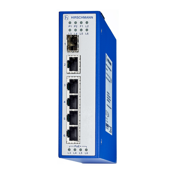
Page 11: Device View
1.3 Device view 1.3.1 Front view SPIDER-SL-44-05T1O6... SPIDER-SL-44-05T199... SPIDER-SL-44-08T19999... SPIDER-SL-44-08T1O6O6... Front view using example of device variants SPIDER-SL-44... SPIDER-SL-44-05T1O6... LED display elements for power supply status 4-pin, pluggable terminal block for power supply LED display elements for port status 1 × SFP slot for 100/1000 Mbit/s F/O connections 1 ×... - Page 12 SPIDER-SL-24-04T1... SPIDER-SL-24-05T1... Front view using example of device variants SPIDER-SL-24... SPIDER-SL-24-04T1... LED display elements for power supply status 4-pin, pluggable terminal block for power supply LED display elements for port status depending on device variant DSC multimode socket for 100 Mbit/s F/O connections ...
-
Page 13: Power Supply
1.4 Power supply You have the following options to supply your device with voltage: Power supply via a 4-pin terminal block For the power supply of the device, a 4-pin terminal block is available. “Wiring the terminal block for the supply For further information see voltage and the grounding”... -
Page 14: 10/100 Mbit/S Twisted Pair Port
100 Mbit/s half-duplex mode, 100 Mbit/s full duplex mode 10 Mbit/s half-duplex mode, 10 Mbit/s full duplex mode Power over Ethernet (PoE/PoE+) 1.5.3 10/100 Mbit/s twisted pair port This port is an RJ45 socket. The 10/100 Mbit/s twisted pair port offers you the ability to connect network components This port supports: ... -
Page 15: Pin Assignments
This port supports: Full duplex mode 1.6 Pin assignments Pin assignment of a TP/TX interface in MDI mode, RJ45 socket RJ45 10/100 Mbit/s 1000 Mbit/s PoE voltage MDI mode BI_DA+ Plus terminal BI_DA- Plus terminal BI_DB+ Minus terminal BI_DC+ BI_DC- BI_DB- Minus terminal... -
Page 16: Display Elements
1.7 Display elements After the supply voltage is switched on, the device performs a self-test. During this process, various LEDs light up. 1.7.1 Power supply state This LED provides information on the status of the power supply. Color Activity Meaning Green Lights up The operating voltage 1 is on... -
Page 17: Port State
1.7.2 Port state These LEDs provide port-related information. LS/DA Color Activity Meaning (link status/data) Green Lights up Device detects a valid link Flashing Device is transmitting and/or receiving data None Device detects an invalid or missing link 1.7.3 PoE state These LEDs provide information on the status of the PoE. -
Page 18: Installation
2 Installation The devices have been developed for practical application in a harsh industrial environment. On delivery, the device is ready for operation. To configure a subdomain, follow these steps: Checking the package contents Mounting the device Installing an SFP transceiver (optional) ... -
Page 19: Mounting The Device
2.2 Mounting the device Installing the device onto the DIN rail 2.2.1 Installing the device onto the DIN rail Prerequisite: The device is for mounting on a 35 mm DIN rail in accordance with DIN EN 60715. Proceed as follows: ... -
Page 20: Installing An Sfp Transceiver (Optional)
2.3 Installing an SFP transceiver (optional) Prerequisite: Use only Hirschmann SFP transceivers which are suitable for usage with the device. See “Accessories” on page 31. Proceed as follows: Remove the protection cap from the SFP transceiver. Push the transceiver with the lock closed into the slot until it latches Installation SPIDER-SL PoE Release 01 05/2019... -
Page 21: Adjust Dip Switch Settings
2.4 Adjust DIP switch settings The 2-pin DIP switch on the top of the device gives you the following options: Device DIP Switch Setting Description SPIDER-SL-44-05T1O6... 100/1GSFP Supports 1000M SFP module Supports 100M SFP module Jumbo Enable Jumbo frame function Disable Jumbo frame function SPIDER-SL-44-05T199... -
Page 22: Wiring The Terminal Block For The Supply Voltage And The Grounding
2.5 Wiring the terminal block for the supply voltage and the grounding WARNING ELECTRIC SHOCK Connect only a supply voltage that corresponds to the type plate of your device. Never insert sharp objects (small screwdrivers, wires, etc.) into the connection terminals for the supply voltage, and do not touch the terminals. -
Page 23: Operating The Device
Proceed as follows: Ensure the required conditions for connecting the supply voltage. See “Requirements for connecting electrical wires” on page 4. Pull the terminal block off the device. Connect the ground connection. Connect the power supply cables. ... -
Page 24: Monitoring The Ambient Air Temperature
3 Monitoring the ambient air temperature Operate the device below the specified maximum ambient air temperature exclusively. See “General technical data” on page 27. The ambient air temperature is the temperature of the air at a distance of 2 in (5 cm) from the device. It depends on the installation conditions of the device, e.g. -
Page 25: Maintenance And Service
4 Maintenance and service When designing this device, Hirschmann largely avoided using high- wear parts. The parts subject to wear and tear are dimensioned to last longer than the lifetime of the product when it is operated normally. Operate this device according to the specifications. Depending on the degree of pollution in the operating environment, check at regular intervals that the ventilation slots in the device are not obstructed. -
Page 26: Disassembly
5 Disassembly 5.1 Removing an SFP transceiver (optional) Proceed as follows: Pull the SFP transceiver out of the slot by means of the opened lock. Close the SFP transceiver with the protective cap. 5.2 Removing the device Proceed as follows: ... -
Page 27: Technical Data
6 Technical data General technical data See “Dimension drawings” on page 28. Dimensions SPIDER Standard Line PoE W × H × D Power supply 2 voltage input 4-pin terminal block Safety extra-low voltage (SELV) Rated voltage range DC 24 V Voltage range DC incl. - Page 28 Dimension drawings Figure 2: Dimensions of device variants SPIDER-SL-24... Figure 3: Dimensions of device variants SPIDER-SL-44... Installation SPIDER-SL PoE Release 01 05/2019...
- Page 29 EMC and immunity EMC interference emission Radiated emission FCC 47 CFR Part 15 Class A EN 55032 Class A Conducted emission FCC 47 CFR Part 15 Class A EN 55032 Class A EMC interference immunity Electrostatic discharge EN 61000-4-2 Contact discharge ±...
- Page 30 Power consumption/ power output at 24V DC Without PoE output Device name Max. power consumption Power output SPIDER-SL-44-05T1... 6.8W 20.3 BTU(IT)/h SPIDER-SL-44-08T1… 7.6W 25.8 BTU(IT)/h SPIDER-SL-24-04T1… 4.1W 13.9 BTU(IT)/h With 120W PoE output Device name Max. power consumption Power output SPIDER-SL-44-05T1...
- Page 31 Accessories Note that products recommended as accessories may have different characteristics to those of the device, which may limit the application range of the overall system. For example, if you add an accessory with IP 20 to a device with IP 65, the IP of the overall system is reduced to Fast-Ethernet-SFP-Transceiver Order number M-FAST SFP-TX/RJ45...
- Page 32 Underlying technical standards Name – EN 55032 Information technology equipment Radio disturbance characteristics – Limits and methods of measurement Electromagnetic compatibility (EMC) – Part 6-2: Generic EN 61000-6-2 standards – Immunity for industrial environments Programmable controllers – Part 2: Equipment requirements and EN 61131-2 tests FCC 47 CFR Part 15...
-
Page 33: Further Support
You will find the addresses of our partners on the Internet at http://www.hirschmann.com. A list of local telephone numbers and email addresses for technical support directly from Hirschmann is available at https://hirschmann-support.belden.com. This site also includes a free of charge knowledge base and a software download section. Hirschmann Competence Center ...
Need help?
Do you have a question about the Hirschmann SPIDER Standard Line Series and is the answer not in the manual?
Questions and answers