Belden Hirschmann RS20 Series User Manual
Industrial ethernet rail switch
Hide thumbs
Also See for Hirschmann RS20 Series:
- User manual (84 pages) ,
- User manual (30 pages) ,
- User manual (74 pages)
Table of Contents
Advertisement
Quick Links
User Manual
Installation
Industrial ETHERNET Rail Switch
RS20/RS22/RS30/RS32/RS40 Family
RS40
FAULT
+24V(P1)
0V 0V
+24V(P2)
P
FAULT
Stand by
RM
RM
ON
Stand by
1
USB
2
V.24
1
2
3
3
4
4
5
6
9
7
8
RS40-0009...
RS32-0802...
RS30
FAULT
+24V(P1)
0V 0V
+24V(P2)
LS
P
FAULT
1
LS
Stand by
RM
DA
RM
ON
Stand by
USB
1
V.24
3
4
LS
5
6
LS
2
2
7
8
DA
9
10
RS30-0802...
RS20-2400...
Installation RS20/22/30/32/40
Release 03 06/2013
RS32
FAULT
+48V(P1)
0V 0V
+48V(P2)
P
FAULT
LS
DA
Stand by
RM
RM
ON
Stand by
USB
1
GB
V.24
3
4
LS
DA
5
6
7
8
2
GB
9
10
RPS90/48V HV
FAULT
+24V(P1)
0V 0V
+24V(P2)
3
4
P
FAULT
DA
Stand by
RM
5
6
RM
ON
Stand by
USB
7
8
9
10
V.24
11
12
DA
13
14
15
16
17
18
RPS90/48V HV
LS
DA
-/N
+/L
1
U: 110 / 230 VAC
U: 60 / 250 VDC
LS
DA
2
P
48-54V
LS
DA
3
0V
LS
DA
+48V / 1,9A
4
RS30-1602...
RS20
RS20
FAULT
+24V(P1)
0V 0V
+24V(P2)
LS
DA
P
FAULT
Stand by
RM
RM
ON
1
Stand by
USB
LS
DA
V.24
2
4
5
19
20
LS
DA
6
7
21
22
3
8
9
23
24
RS20-0900...
RS30
FAULT
+24V(P1)
0V 0V
+24V(P2)
P
FAULT
Stand by
RM
RM
ON
Stand by
USB
V.24
5
6
7
8
13
14
9
10
15
16
11
12
17
18
RS20
FAULT
+24V(P1)
0V 0V
+24V(P2)
P
FAULT
LS
DA
Stand by
RM
RM
ON
Stand by
USB
1
V.24
LS
DA
3
4
2
5
6
7
8
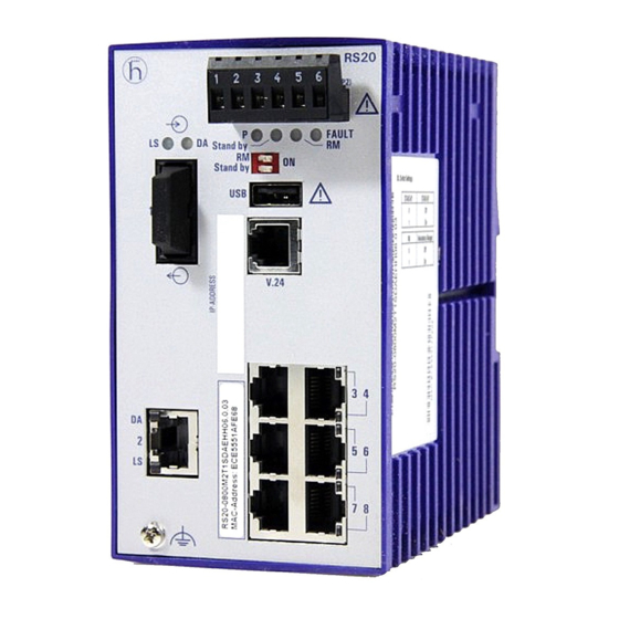
RS20-0800...
Technical support
https://hirschmann-support.belden.eu.com
RS20
FAULT
+24V(P1)
0V 0V
+24V(P2)
P
FAULT
Stand by
RM
RM
ON
Stand by
USB
V.24
LS
1
DA
LS
2
DA
LS
3
DA
LS
4
DA
RS20-0400...
Advertisement
Table of Contents

Subscribe to Our Youtube Channel
Related Manuals for Belden Hirschmann RS20 Series


Summary of Contents for Belden Hirschmann RS20 Series
- Page 1 FAULT FAULT Stand by Stand by Stand by Stand by Stand by Stand by Stand by Stand by Stand by Stand by V.24 V.24 V.24 V.24 V.24 RS30-0802... RS20-2400... RS20-0900... RS20-0800... RS20-0400... Installation RS20/22/30/32/40 Technical support Release 03 06/2013 https://hirschmann-support.belden.eu.com...
- Page 2 The naming of copyrighted trademarks in this manual, even when not specially indicated, should not be taken to mean that these names may be considered as free in the sense of the trademark and tradename protection law and hence that they may be freely used by anyone. ©...
-
Page 3: Table Of Contents
Contents Safety instructions About this Manual Description Description of the device variants 1.1.1 Combination options for RS20/30 1.1.2 Combination options for RS40 1.1.3 Number of ports and media for RS20-... 1.1.4 Number of ports and media for RS30-... 1.1.5 Number of ports and media for RS40-... Device variants with PoE (optional) 1.2.1 Number of ports and media for devices with PoE 1.2.2 PoE power units... -
Page 4: Safety Instructions
Safety instructions Certified usage Please observe the following: The device may only be employed for the purposes described in the catalog and technical description, and only in conjunction with external devices and components recommended or approved by the manufacturer. The product can only be operated correctly and safely if it is transported, stored, installed and assembled properly and correctly. - Page 5 Supply voltage for PoE power supply units (optional) Connect the protective conductor with the ground screw before you set up the other connections. When removing the connections, you remove the protective conductor last. Make sure that the cross-section of the protective conductor cable is the same size as or bigger than the cross-section of the voltage supply cables.
- Page 6 Hazardous Locations Relevant for North America for devices certified for Hazardous Locations: Power, input and output (I/O) wiring must be in accordance with Class I, Division 2 wiring methods [Article 501-4(b) of the National Electrical Code, NFPA 70] and in accordance with the authority having jurisdiction. SUITABLE FOR USE IN CLASS I, DIVISION 2, GROUPS A, B, C AND D HAZARDOUS LOCATIONS, OR NON-HAZARDOUS LOCATIONS ONLY.
- Page 7 CONTROL DRAWING: Hazardous Locations Class I, Division 2, Groups A, B ,C ,D HAZARDOUS LOCATION NON HAZARDOUS LOCATION Power supply: USB Port for Auto Configuration (Redundant: P1 P2) Adapter. Type “D”: 9.6Vdc – 60Vdc For maintenance only Fault contacts. Equipment with nonincendive field wiring parameters: V<30V I<90mA L <1,0µH C...
- Page 8 ATEX directive 94/9/EG – specific regulations for safe operation Relevant for RS20/22/30/32/40 devices when operating in explosive gas atmospheres according to ATEX Directive 94/9/EC, the following applies: List of Standards: EN 60079-0:2009 EN60079-15:2010 Certificate No.: DEKRA 11ATEX0139 X or KEMA 09ATEX0067 X. ...
- Page 9 When the temperature under rated conditions exceeds 70 °C at the cable or conduit entry point, or 80 °C at the branching point of the conductors, the temperature specification of the selected cable and cable entries shall be in compliance with the actual measured temperature values.
- Page 10 For the ground conductor, use a cable with a cross section of at least 1.0 mm². Make sure there is at least 3.94 in (10 cm) of space in front of the ventilation slits of the housing. The device must be installed in the vertical position. ...
- Page 11 Non-observance of these safety instructions can cause material damage and/or injuries. Only appropriately qualified personnel should work on this device or in its vicinity. The personnel must be thoroughly familiar with all the warnings and maintenance procedures outlined in this operating manual.
- Page 12 2004/108/EG (EMV) Directive of the European Parliament and the council for standardizing the regulations of member states with regard to electromagnetic compatibility. RPS90/48V HV: 2006/95/EG Directive of the European Parliament and the council for standardizing the regulations of member states with regard to electrical equipment to be used within specific voltage ranges.
- Page 13 Recycling note After usage, this device must be disposed of properly as electronic waste, in accordance with the current disposal regulations of your county, state, and country. Installation RS20/22/30/32/40 Release 03 06/2013...
-
Page 14: About This Manual
About this Manual The “Installation” user manual contains a device description, safety instructions, a description of the display, and the other information that you need to install the device. The following manuals are available as PDF files on the CD/DVD supplied: ... -
Page 15: Description
Description You can choose from between a wide range of variants. You have the option to set up your device individually based on different criteria: Number of ports Transmission speed Media type Types of connectors Temperature range ... -
Page 16: Description Of The Device Variants
Product configuration data can be provided by: diagnosis displays displaying the operating parameters a label area for the IP address The devices provide you with a large range of functions, which the manuals for the operating software inform you about. You will find these manuals as PDF files on the enclosed CD/DVD, or you can download them from the Internet on the Hirschmann product pages (www.hirschmann.com). -
Page 17: Combination Options For Rs20/30
Uplink ports Other ports PoE ports included Variant Numbe Type Number Type Numbe Type RS30-... 2 Ports 1 and 2 8, 16, 24 10/100 Mbit/s, — — 1000 Mbit/s, TP, RJ45 media selectable, SFP, RJ45 Ports 1+2, 3+4 6, 14, 22 10/100 Mbit/s, —... - Page 18 Item Characteristic Ident. Ident. Property Mbit/s ports 2 × 1000 Mbit/s Ethernet (not for 4 port devices) 10 and 11 Uplink port(s) Twisted pair T(X), RJ45 1 port (Ident. Multimode FX, DSC, 100 Mbit/s column) or alternatively Multimode FX, ST, 100 Mbit/s 2 ports Singlemode FX, DSC, 100 Mbit/s (Ident.2 column)
- Page 19 Devices with ports with product code E2 or EE: only certification “A” available (see product code for item 16). m. For RS20-0900..., RS20-1700..., RS20-2500...; RS22-0900..., RS22-1700..., RS22-2500... n. For RS20-0900..., RS20-1700..., RS20-2500...; RS22-0900..., RS22-1700..., RS22-2500... o. Not in combination with “04×100 Mbit/s Ethernet”. p.
-
Page 20: Combination Options For Rs40
Additional examples of devices with 3 or 4 uplink ports: RS20-0900NNM4TDAE for RS20 with 3 uplink ports (ST) NN: 2 × Multimode FX, ST, 100 Mbit/s (ports 1 and 2) M4: 1 × Multimode FX, ST, 100 Mbit/s (port 3) ... -
Page 21: Number Of Ports And Media For Rs20
Examples for product name RS40- Rail Switch with gigabit ports 0 × 100 Mbit/s Ethernet ports 9 × 1000 Mbit/s Ethernet ports Port 1 + 2 = combo port: SFP slot (100/1000 Mbit/s), alternatively: RJ45 connector (10/100/1000 Mbit/s) Port 3 + 4 = combo port: SFP slot (100/1000 Mbit/s), alternatively: RJ45 connector (10/100/1000 Mbit/s) Temperature range extended (-40 °C to +70 °C) with conformal coating Voltage range: 9.6 V DC to 60 V DC or 18 V AC to 30 V AC... - Page 22 M4: Multimode FX, ST, 100 Mbit/s S2: Singlemode FX, DSC, 100 Mbit/s S4: Singlemode FX, ST, 100 Mbit/s L2: Singlemode Longhaul FX, DSC, 100 Mbit/s G2: Singlemode Longhaul+ FX, DSC, 100 Mbit/s, 200 km 8 – MAC address field 9 – IP address field RS20 FAULT +24V(P1)
- Page 23 RS20 FAULT +24V(P1) 0V 0V +24V(P2) FAULT Stand by Stand by V.24 RS20 RS20 FAULT FAULT +24V(P1) 0V 0V +24V(P2) +24V(P1) 0V 0V +24V(P2) FAULT FAULT Stand by Stand by Stand by Stand by V.24 V.24 RS20-1600T1T1...D... RS20-1600M2M2...D... RS20-1600M2T1...D... Figure 3: Device variants with 16 × 10/100 Mbit/s ports (RS20-1600...) 1 to 9 –...
- Page 24 FAULT RS20 FAULT RS20 FAULT RS20 +24V(P1) 0V 0V +24V(P2) +24V(P1) 0V 0V +24V(P2) +24V(P1) 0V 0V +24V(P2) FAULT FAULT FAULT Stand by Stand by Stand by Stand by Stand by Stand by V.24 V.24 V.24 RS20-2500MMM2...D... RS20-1700MMM2...D... RS20-0900MMM2...D... Figure 5: Device variants with 3 uplink ports (100 Mbit/s) 1 to 6 –...
-
Page 25: Number Of Ports And Media For Rs30
1.1.4 Number of ports and media for RS30-... RS30 FAULT +24V(P1) 0V 0V +24V(P2) FAULT Stand by Stand by V.24 RS30 RS30 FAULT FAULT +24V(P1) 0V 0V +24V(P2) +24V(P1) 0V 0V +24V(P2) FAULT FAULT Stand by Stand by Stand by Stand by V.24 V.24... - Page 26 RS30 FAULT +24V(P1) 0V 0V +24V(P2) FAULT Stand by Stand by V.24 RS30 RS30 FAULT FAULT +24V(P1) 0V 0V +24V(P2) +24V(P1) 0V 0V +24V(P2) FAULT FAULT Stand by Stand by Stand by Stand by V.24 V.24 RS30-1602T1T1...D... RS30-1602O6O6...D... RS30-1602O6T1...D... Figure 7: Device variants with 2 × 1000 Mbit/s ports and 16 × 10/100 Mbit/s ports (RS30-1602...) 1 to 9 –...
- Page 27 RS30 RS30 RS30 FAULT FAULT FAULT +24V(P1) 0V 0V +24V(P2) +24V(P1) 0V 0V +24V(P2) +24V(P1) 0V 0V +24V(P2) FAULT FAULT FAULT Stand by Stand by Stand by Stand by Stand by Stand by V.24 V.24 V.24 RS30-2402OOZZ...D... RS30-1602OOZZ...D... RS30-0802OOZZ...D... Figure 9: Device variants with 4 uplink ports 1 to 6 –...
-
Page 28: Number Of Ports And Media For Rs40
1.1.5 Number of ports and media for RS40-... RS40 FAULT +24V(P1) 0V 0V +24V(P2) FAULT Stand by Stand by V.24 FAULT RS40 +24V(P1) 0V 0V +24V(P2) FAULT Stand by Stand by V.24 RS40-0009CCCCED... RS40-0009CCCCSD... RS40-0009CCCCTD... Figure 10: Device variants with 9 × 1000 Mbit/s ports (RS40-0009...) 1 to 5 and 8 to 9 –... -
Page 29: Device Variants With Poe (Optional)
Device variants with PoE (optional) 1.2.1 Number of ports and media for devices with PoE FAULT RS22 +48V(P1) 0V 0V +48V(P2) FAULT Stand by Stand by V.24 RS22-1700MMM2...P... Figure 11: RS22 device variants with PoE (example: RS22-1700MMM2...P...) 1 to 5 and 7 to 9 – see figure 5 6 –... - Page 30 RS32 FAULT +48V(P1) 0V 0V +48V(P2) FAULT Stand by Stand by V.24 RS32-0802OOZZ...P... Figure 12: RS32 device variants with 4 uplink ports (example: RS32- 0802OOZZ...P...) 1 to 5 and 7 to 9 – see figure 9 6 – ports in compliance with 10/100BASE-T(X) (RJ45 connections; the PoE-capable ports 7 to 10 are indicated accordingly) Device variants RS22-...
-
Page 31: Poe Power Units
1.2.2 PoE power units The following PoE power units are available for supplying the devices with PoE voltage: RPS90/48V LV: Low-voltage PoE power unit Input voltage range: 24 V DC to 48 V DC Power output at up to +60 °C: 90 W Power output at +60 °C to +70 °C: 60 W ... -
Page 32: Assembly And Start-Up
Assembly and start-up The devices have been developed for practical application in a harsh industrial environment. On delivery, the device is ready for operation. Two or more devices configured with the same IP address can cause unpredictable operation of your network. WARNING UNINTENTIONAL OPERATION IN DEVICE Install and maintain a process that assigns a unique IP address to every... -
Page 33: Installing The Sfp Transceivers (Optional)
2.1.2 Installing the SFP transceivers (optional) Before attaching an SFP or XFP transceiver, first remove the protective cap of the SFP/XFP transceiver. Push the SFP/XFP transceiver with the lock closed into the socket until it latches audibly in place. Figure 13: F/O SFP transceiver Note: Only use Hirschmann SFP transceivers. -
Page 34: Adjust Dip Switch Settings
2.1.4 Adjust DIP switch settings The 2-pin DIP switch on the front panel of the device gives you the following options: Stand by Figure 15: 2-pin DIP switch Switch Switch Ring Coup- Ring Coupli Ring Control Coup Software stand-by redun- ling Manag port... - Page 35 FAULT FAULT +24V(P1) 0V 0V +24V(P2) +24V(P1) 0V 0V +24V(P2) Figure 16: Connecting the supply voltage at the 6-pin terminal block 1 – DC voltage, voltage range: 9.6 V DC to 60 V DC 2 – AC voltage, voltage range: 18 V AC to 30 V AC Note: With non-redundant supply of the mains voltage, the device reports a power failure.
-
Page 36: Rs22/Rs32: Supply Voltage And Signal Contact
The following condition is also reported in RM mode: Ring redundancy reserve is available. On delivery, there is no ring redundancy monitoring. Pull the terminal block off the device and connect the power supply and signal lines. 2.1.6 RS22/RS32: supply voltage and signal contact For the RS22/RS32, the PoE supply voltage and the signal contact are connected via the 6-pin terminal block with a snap lock. - Page 37 First connect the protective conductor to the protective conductor terminal. Connect the DC voltage to the 2-pin terminal block. Use a supply cable with a maximum length of 2 meters to the power unit. RPS90/48V HV: connecting the input voltage ...
- Page 38 RS22/RS32 supply voltage The RPS90/48V LV and RPS90/48V HV PoE power supply units provide an output voltage of typically 48 V DC for supplying the RS22-.../RS32-... devices with the PoE voltage. Caution! Note the “Safety instructions” on page 4 and only connect a supply voltage that corresponds to the type plate of your device.
- Page 39 The potential-free signal contact (relay contact, closed circuit) reports through a break in contact: The detected inoperability of at least one of the two voltage supplies (voltage supply 1 or 2 is below the threshold value). The device is not operational. ...
-
Page 40: Installing The Device On The Din Rail, Grounding
2.1.7 Installing the device on the DIN rail, grounding Mounting on the DIN rail The devices are mounted very quickly by snapping them onto the DIN rail. Mount the device on a 35 mm DIN rail in accordance with DIN EN 60175. - Page 41 DIN rail mounting on ships (RS30-0802...) When you are mounting your RS30-0802... Open Rail device on a DIN rail on ships and in similar applications, the Open Rail Mounting Kit available as an accessory can be used to avoid excessive resonance. ...
- Page 42 Mounting on the wall (RS22/RS32) In addition to the option of mounting them on a DIN rail, you can also mount the RS22/RS32 devices on the wall using the wall mounting plate supplied “Accessories” on page Figure 20: Mounting the RS22/RS32 devices on the wall ...
-
Page 43: Dimension Drawings
Grounding With the RS20/RS30/RS40, the front panel of the device is grounded via the separate ground screw. With the RS22/RS32, the front panel and the metal housing of the device is grounded via the separate ground screw. For the ground conductor, use a cable with a cross section of at least 1.0 mm². - Page 44 105,3 13,73 Figure 22: Dimensions of device variants RS20.../RS30.../RS40... with 8 to max. 10 ports Figure 23: Dimensions of device variants RS20.../RS30.../RS40... with 16 to max. 26 ports Installation RS20/22/30/32/40 Release 03 06/2013...
- Page 45 Dimension drawings for RS22/RS32 11,56 Figure 24: Dimensions of device variants RS22.../RS32... with 8 to max. 10 ports 11,56 Figure 25: Dimensions of device variants RS22.../RS32... with 16 to max. 26 ports Installation RS20/22/30/32/40 Release 03 06/2013...
-
Page 46: Connecting The Ferrite
Dimension drawings for PoE power units 7,05 Figure 26: Dimensions of RPS90/48V LV and RPS90/48V HV PoE power units 2.1.9 Connecting the ferrite Note: For PoE devices with 16 or more ports (RS22-16..., RS22-17..., RS22-24... and RS22-25...): To adhere to EMC conformity, you connect the ferrite supplied to the voltage input via the voltage supply line. -
Page 47: Installing The Terminal Block, Start-Up Procedure
Figure 27: Connecting the ferrite to the voltage supply line 2.1.10 Installing the terminal block, start-up procedure WARNING ELECTRIC SHOCK Ground the device before connecting the power supply. Failure to follow these instructions can result in death, serious injury, or equipment damage. ... - Page 48 These ports support: Autonegotiation Autopolarity Autocrossing (if autonegotiation is activated) 100 Mbit/s half-duplex mode, 100 Mbit/s full duplex mode 10 Mbit/s half-duplex mode, 10 Mbit/s full duplex mode Delivery state: autonegotiation activated The socket housing is electrically connected to the front panel. Figure Operation One line pair: receiver path...
- Page 49 Figure Function Receive Data + Receive Data - Transmit Data + Transmit Data - 4,5,7,8 Not used Table 12: Pin assignment of a TP/TX interface for PoE for the voltage supply to the wire pairs transmitting the signal, RJ45 socket, MDI-X mode 10/100/1000 Mbit/s twisted pair connection ...
-
Page 50: Display Elements
100 MBit/s F/O ports enable the connection of terminal devices or independent network segments in compliance with the IEEE 802.3 100BASE-FX standard. These ports support: Full or half duplex mode Default setting: Full duplex Note: Make sure that the LH ports are only connected with LH ports, SM ports are only connected with SM ports, and MM ports only with MM ports. - Page 51 FAULT Stand by Figure 28: Device status LEDs P - Power (green/yellow LED) Glowing green Both supply voltages are on Glowing yellow There is only one supply voltage (P1 or P2) on Not glowing Supply voltages P1 and P2 are too low FAULT - detected error, signal contact (red LED) Glowing red The signal contact is open, i.e.
-
Page 52: Basic Set-Up
LS - link status (green LED) Not glowing No valid connection. Glowing green Valid connection. Flashing green (1 time a period) Port is switched to stand-by. Flashing green (3 times a Port is switched off. period) DA - data (yellow LED) Not glowing No data reception at corresponding port Flashing yellow... - Page 53 Figure Operation VCC (VBus) − Data + Data Ground (GND) Table 14: Pin assignment of the USB interface V.24 interface (external management) The V.24 interface is an RJ11 socket. At the V.24 connection, a serial interface is provided for the local connection of an external management station (VT100 terminal or PC with corresponding terminal emulation) or an AutoConfiguration Adapter ACA 11.
-
Page 54: Maintenance
Maintenance When designing this device, Hirschmann was largely able to forego using parts that are subject to wear and tear. The parts subject to wear are designed to last longer than the lifetime of the product when it is operated properly. -
Page 55: Disassembly
Disassembly Removing the device from the DIN rail To take the device off the DIN rail, insert a screwdriver horizontally under the housing into the locking slide, pull it (without tipping the screwdriver) downwards and lift the device upwards. RS20/RS30/RS40 RS22/RS32 Removing the device from the wall mounting plate... -
Page 56: Technical Data
Technical data General technical data Dimensions RS20-0400... 47 mm × 131 mm × 111 mm W x H x D RS20-08..., RS20-09..., RS30-0802 74 mm × 131 mm × 111 mm RS20-16..., RS20-17..., RS30-1602 110 mm × 131 mm × 111 mm RS20-24..., RS20-25..., RS30-2402 110 mm ×... - Page 57 PoE power unit Nominal voltage AC 110 V ... 230 V, 50 Hz ... 60 Hz RPS90/48V HV Voltage range AC 90 - 265 V, 47 - 63 Hz (incl. max. tolerances) Power consumption at 110 V AC 1.00 A Power consumption at 230 V AC 0.50 A Nominal voltage DC...
- Page 58 Operating RS20/RS30/RS40 Standard: 0 °C to +60 °C temperature Extended: -40 °C to +70 °C RS22-..., RS32-... Standard: 0 °C to +60 °C Extended: -40 °C to +60 °C RS40-...B... (ATEX) Temperature Code T4: Standard (S) +32 °F ... +140 °F (0 °C ... +60 °C) RS40-...B...
- Page 59 EMC interference emission EN 55022 Class A FCC 47 CFR Part Class A German Lloyd Classification + Construction Guidelines VI- — 7-3 Part 1 Ed.2001 Stability Vibration IEC 60068-2-6 Test FC test level according to IEC 61131-2 Germanischer Lloyd Guidelines for the —...
- Page 60 e. including 2.5 dB system reserve when compliance with the fiber data is observed Product Wave Wave Fiber System Example Fiber Dispersion code length length attenuat for F/O attenuati M-SFP- line BIDI... length Type A SM 1310 nm 1550 nm 9/125 µm 0-11 dB 0-20 km 0.4 dB/km 3.5 ps/(nm×km) LX/LC Type B SM 1550 nm 1310 nm 9/125 µm 0-11 dB 0-20 km 0.25...
- Page 61 MM = Multimode, SM = Singlemode, LH = Singlemode Longhaul TP port Length of a twisted pair segment max. 100 m/328 ft (for cat5e cable) Table 19: TP port 10BASE-T / 100BASE-TX / 1000BASE-T Power consumption/power output Device name Device model Maximum Power output...
- Page 62 Device name Device model Maximum Power output power consumption 2 uplink ports: RS22-0800... 2xTX port 70.9 W 31.8 Btu (IT)/h RS22-0800... 1xFX port, 1xTX port 72.1 W 35.9 Btu (IT)/h RS22-0800... 2xFX port 73.3 W 40.0 Btu (IT)/h RS22-1600... 2xTX port 75.0 W 45.8 Btu (IT)/h RS22-1600...
- Page 63 Accessories Gigabit Ethernet SFP transceiver Order number M-SFP-TX/RJ45 943 977-001 M-SFP-SX / LC 943 014-001 M-SFP-SX/LC EEC 943 896-001 M-SFP-MX/LC 942 035-001 M-SFP-LX/LC 943 015-001 M-SFP-LX/LC EEC 943 897-001 M-SFP-LX+/LC 942 023-001 M-SFP-LX+/ LC EEC 942 024-001 M-SFP-LH/LC 943 042-001 M-SFP-LH/LC EEC 943 898-001 M-SFP-LH+/LC...
- Page 64 Other accessories Order number Industrial HiVision Network Management Software 943 156-xxx OPC server software HiOPC 943 055-001 Underlying norms and standards Name UL 508 Safety for Industrial Control Equipment EN 50121-4 Railway applications - EMC - emitted interference and interference immunity for signal and telecommunication systems EN 55022 Information technology equipment –...
-
Page 65: A Further Support
Contact our support at https://hirschmann-support.belden.eu.com You can contact us in the EMEA region at Tel.: +49 (0)1805 14-1538 E-mail: hac.support@belden.com in the America region at Tel.: +1 (717) 217-2270 E-mail: inet-support.us@belden.com in the Asia-Pacific region at ...
Need help?
Do you have a question about the Hirschmann RS20 Series and is the answer not in the manual?
Questions and answers