
Related Manuals for Belden HIRSCHMANN SPIDER SSR40-5TX


Summary of Contents for Belden HIRSCHMANN SPIDER SSR40-5TX
- Page 1 User Manual Installation Industrial Ethernet Rail Switch SPIDER Standard Line Installation SPIDER-SL Technical support Release 09 08/2024 https://hirschmann-support.belden.com...
- Page 2 The naming of copyrighted trademarks in this manual, even when not specially indicated, should not be taken to mean that these names may be considered as free in the sense of the trademark and tradename protection law and hence that they may be freely used by anyone. ©...
-
Page 3: Table Of Contents
Contents Important information Safety instructions About this Manual Description General device description Device name and product code Device view 1.3.1 Front view Power supply 1.4.1 Supply voltage with the characteristic value HH 1.4.2 Supply voltage with characteristic value HK Ethernet ports 1.5.1 10/100/1000 Mbit/s twisted pair port 1.5.2 10/100 Mbit/s twisted pair port 1.5.3 100/1000 Mbit/s F/O port... - Page 4 2.4.2 Connecting the 3-pin voltage terminal with spring (device variants with the characteristic value HK) Operating the device Connecting data cables Monitoring the ambient air temperature Maintenance and service Disassembly Removing an SFP transceiver (optional) Removing the device Technical data Open Source Software used in the product Further support Installation SPIDER-SL...
-
Page 5: Important Information
Important information Note: Read these instructions carefully, and familiarize yourself with the device before trying to install, operate, or maintain it. The following notes may appear throughout this documentation or on the device. These notes warn of potential hazards or call attention to information that clarifies or simplifies a procedure. - Page 6 NOTICE NOTICE provides information about procedures that do not involve the risk of injury. Installation SPIDER-SL Release 09 08/2024...
-
Page 7: Safety Instructions
Safety instructions General safety instructions You operate this device with electricity. Improper usage of the device entails the risk of physical injury or significant property damage. The proper and safe operation of this device depends on proper handling during transportation, proper storage and installation, and careful operation and maintenance procedures. - Page 8 Strain relief Note: If the strain relief is insufficient, there is a potential risk of torsion, contact problems and creeping interruptions. Relieve the connection points of cables and lines from mechanical stress. Design strain reliefs in such a way that they help prevent any mechanical damage to cables, wires or conductors caused by external influences or their own weight.
- Page 9 Shielding ground The shielding ground of the connectable twisted pair cables is connected to the ground connection as a conductor. Beware of possible short circuits when connecting a cable section with conductive shielding braiding. Requirements for connecting electrical wires ...
- Page 10 CE marking The labeled devices comply with the regulations contained in the following European directive(s): 2011/65/EU and 2015/863/EU (RoHS) Directive of the European Parliament and of the Council on the restriction of the use of certain hazardous substances in electrical and electronic equipment.
- Page 11 Supplier's Declaration of Conformity 47 CFR § 2.1077 Compliance Information SPIDER-SL U.S. Contact Information Belden – St. Louis 1 N. Brentwood Blvd. 15th Floor St. Louis, Missouri 63105, United States Phone: 314.854.8000 This device complies with part 15 of the FCC Rules. Operation is subject...
-
Page 12: About This Manual
About this Manual The “Installation” user manual contains a device description, safety instructions, a description of the display, and the other information that you need to install the device. Documentation mentioned in the “User Manual Installation” that is not supplied with your device as a printout can be found as PDF files for downloading on the Internet at: https://www.doc.hirschmann.com Installation SPIDER-SL... -
Page 13: Key
The symbols used in this manual have the following meanings: Listing Work step Subheading Installation SPIDER-SL Release 09 08/2024... -
Page 14: Description
You have numerous options of combining the device characteristics. You can determine the possible combinations using the configurator which is available in the Belden Online Catalog https://catalog.belden.com on the web page of the device. -
Page 15: Device Name And Product Code
Device name and product code The device name corresponds to the product code. The product code is made up of characteristics with defined positions. The characteristic values stand for specific product properties. The following device variants have a corresponding short designation in addition to the product code: Short designation Product code... -
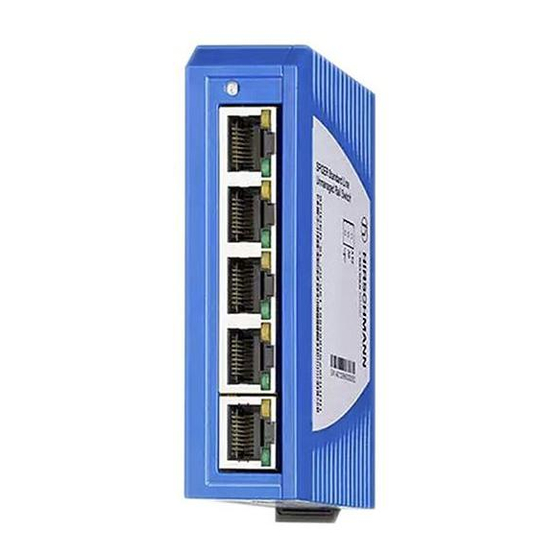
Page 16: Device View
Item Characteristic Character Description istic value 22 ... 23 Optical fiber port 3 without Temperature range Standard 0 °C ... +60 °C (+32 °F ... +140 °F) Derating Extended -40 °C ... +70 °C (-40 °F ... +158 °F) 25 ... 26 Certificates and CE, FCC, EN 61131, RCM declarations Z9 + cUL 61010... - Page 17 3-pin, pluggable terminal block for power supply LED display elements for port status depending on device variant DSC multimode socket for 100 Mbit/s F/O connections DSC singlemode socket for 100 Mbit/s F/O connections RJ45 socket for 10/100 Mbit/s Twisted pair connections Rail lock slide for DIN rail mounting 7 ...
-
Page 18: Power Supply
LED display elements for device status 3-pin, pluggable terminal block for power supply LED display elements for port status SFP slot for 100/1000 Mbit/s F/O connections 5 ... 6 2 × RJ45 socket for 10/100/1000 Mbit/s Twisted Pair connections Rail lock slide for DIN rail mounting 8 ... -
Page 19: 10/100/1000 Mbit/S Twisted Pair Port
1.5.1 10/100/1000 Mbit/s twisted pair port This port is an RJ45 socket. The 10/100/1000 Mbit/s twisted pair port allows you to connect network components according to the IEEE 802.3 10BASE-T/100BASE-TX/ 1000BASE-T standard. This port supports: Autonegotiation Autopolarity Autocrossing ... -
Page 20: Pin Assignments
Pin assignments RJ45 10/100 Mbit/s 1000 Mbit/s MDI mode BI_DA+ TX− BI_DA− BI_DB+ — BI_DC+ — BI_DC− RX− BI_DB− — BI_DD+ — BI_DD− MDI-X mode BI_DB+ RX− BI_DB− BI_DA+ — BI_DD+ — BI_DD− TX− BI_DA− — BI_DC+ — BI_DC− Display elements After the supply voltage is switched on, the device performs a self-test. -
Page 21: Port Status
Color Activity Meaning green lights up Supply voltage is on Device is ready for operation none Supply voltage is too low Device is not ready for operation 1.7.2 Port status These LEDs provide port-related information. Color Activity Meaning (link status/data) green lights up Device detects a valid link... -
Page 22: Installation
Installation The devices have been developed for practical application in a harsh industrial environment. On delivery, the device is ready for operation. To install the device, perform the following work steps: Checking the package contents Mounting the device ... - Page 23 Perform the following work steps: Slide the upper snap-in guide of the device into the DIN rail. Use a screwdriver to pull the rail lock slide downwards. Snap in the device by releasing the rail lock slide. Installation SPIDER-SL Release 09 08/2024...
-
Page 24: Mounting On A Flat Surface
2.2.2 Mounting on a flat surface inch 57,5 2.26 1.65 24,25 0.95 35,75 1.41 inch 87,5 3.44 2.83 54,25 2.14 65,75 2.59 Perform the following work steps: Attach the wall mounting plate to a flat surface of the wall using screws. You will find the dimensions necessary for mounting the device in the illustration. -
Page 25: Installing An Sfp Transceiver (Optional)
Installing an SFP transceiver (optional) Prerequisites: Exclusively use Hirschmann SFP transceivers. See “Accessories” on page 38. Figure 1: Installing SFP transceivers: Installation sequence Perform the following work steps: Take the SFP transceiver out of the transport packaging (1). Remove the protection cap from the SFP transceiver (2). ... -
Page 26: Connecting The 3-Pin Terminal Block (Device Variants With Characteristic Value Hh)
The shielding ground of the connectable twisted pair cables is connected to the ground connection as a conductor. 2.4.1 Connecting the 3-pin terminal block (device variants with characteristic value HH) Figure 2: 3-pin terminal block, characteristic value HH Type of the voltages Specification of the supply Pin assignment that can be... -
Page 27: Connecting The 3-Pin Voltage Terminal With Spring (Device Variants With The Characteristic Value Hk)
Fasten the wires in the terminal block by tightening the terminal screws. Mount the terminal block for the supply voltage and the ground by plugging them in. 2.4.2 Connecting the 3-pin voltage terminal with spring (device variants with the characteristic value HK) Figure 3: 3-pin voltage terminal with spring, characteristic value HK Type of the voltages Specification of the supply... -
Page 28: Operating The Device
Open the terminal lock by pressing the corresponding lever with a screwdriver. Connect the wires according to the pin assignment on the device with the clamps. Mount the terminal block for the supply voltage and the ground by plugging them in. -
Page 29: Monitoring The Ambient Air Temperature
Monitoring the ambient air temperature Operate the device below the specified maximum ambient air temperature exclusively. See “General technical data” on page 33. The ambient air temperature is the temperature of the air at a distance of 5 cm (2 in) from the device. It depends on the installation conditions of the device, for example the distance from other devices or other objects, and the output of neighboring devices. -
Page 30: Maintenance And Service
Maintenance and service When designing this device, Hirschmann largely avoided using high-wear parts. The parts subject to wear and tear are dimensioned to last longer than the lifetime of the product when it is operated normally. Operate this device according to the specifications. Depending on the degree of pollution in the operating environment, check at regular intervals that the ventilation slots in the device are not obstructed. -
Page 31: Disassembly
Disassembly Removing an SFP transceiver (optional) Figure 4: De-installing SFP transceivers: De-installation sequence Perform the following work steps: Open the locking mechanism of the SFP transceiver (1). Pull the SFP transceiver out of the slot via the open locking mechanism (2). - Page 32 Perform the following work steps: Disconnect the data cables. Disable the supply voltage. Remove the terminal connector from the device. Use a screwdriver to pull the rail lock slide downwards. Pull the device downwards from the DIN rail module. Installation SPIDER-SL Release 09 08/2024...
-
Page 33: Technical Data
Technical data General technical data Dimensions SPIDER Standard Line See “Dimension drawings” on W × H × D page 34. Weight SPIDER-SL-20-01T1... 120 g (4.23 oz) SPIDER-SL-20-04T1... 130 g (4.59 oz) SPIDER-SL-20-06T1M29... 225 g (7.94 oz) SPIDER-SL-20-06T1S29... 225 g (7.94 oz) SPIDER-SL-20-06T1M2M... - Page 34 b. For device variants SPIDER SL-40-06T1O6O699SZ9HHHH and SSR40-6TX/2SFP, the maximum permitted ambient air temperature has to be reduced to +50 °C (+122 °F). Dimension drawings 14,3 14,3 13,8 14,3 inch 25,5 25,5 37,8 SPIDER-SL-20-06T1... SPIDER-SL-20-01T1... SPIDER-SL-20-08T1... SPIDER-SL-20-04T1... Figure 5: Dimensions of device variants SPIDER-SL-20... Installation SPIDER-SL Release 09 08/2024...
- Page 35 13,8 14,3 13,8 14,3 inch 25,5 37,8 SSR40-6TX/2SFP SPIDER-SL-40-06T1... SSR40-5TX SSR40-8TX Figure 6: Dimensions of device variants SPIDER-SL-40... Installation SPIDER-SL Release 09 08/2024...
- Page 36 EMC and immunity Note: Use shielded data cables for gigabit transmission via copper cables. Use shielded data cables for all transmission rates to meet the requirements according to EN 50121-4 and marine applications. EMC interference emission Radiated emission FCC 47 CFR Part 15 Class A EN 55032 Class A...
- Page 37 Network range 10/100/1000 Mbit/s twisted pair port Length of a twisted pair segment max. 100 m (328 ft) (for Cat5e cable) Table 5: Network range: 10/100/1000 Mbit/s twisted pair port Power consumption/power output at 24 V DC Device name Max.
- Page 38 Device Order number SPIDER-SL-20-08T1999999SZ9HHHH 942-132-002 SPIDER-SL-40-05T1999999SZ9HHHH 942-132-003 SSR40-5TX (SPIDER-SL-40-05T1999999SxxxxHHxx) 942-335-003 SPIDER-SL-40-06T1O69999SZ9HHHH 942-132-014 SPIDER-SL-40-06T1O6O699SZ9HHHH 942-132-015 SSR40-6TX/2SFP (SPIDER-SL-40-06T1O6O699SxxxxHHxx) 942-335-015 SPIDER-SL-40-08T1999999SYZ9HHHH 942-132-004 SSR40-8TX (SPIDER-SL-40-08T1999999SxxxxHHxx) 942-335-004 SSR40-5TX-IP (SPIDER-SL-40-05T1999999SxxxxHIxx) 942-335-013 SSR40-8TX-IP (SPIDER-SL-40-08T1999999SxxxxHIxx) 942-335-014 SSR40-5TX-PN (SPIDER-SL-40-05T1999999SxxxxHPxx) 942-335-023 SSR40-8TX-PN (SPIDER-SL-40-08T1999999SxxxxHPxx) 942-335-024 Accessories Note that products recommended as accessories may have different characteristics to those of the device, which may limit the application range of the overall system.
- Page 39 942 205-002 SFP-FAST-BA SM+/LC EEC 942 206-001 SFP-FAST-BB SM+/LC EEC 942 206-002 a. You find further information on certifications on the Internet at the Belden product pages (https://belden.com). Bidirectional Gigabit Ethernet SFP transceiver Order number M-SFP-BIDI Type A LX/LC EEC...
- Page 40 Underlying technical standards Name CSA C22.2 No. 142 Canadian National Standard(s) – Process Control Equipment – Industrial Products EN 50121-4 Railway applications – EMC – Emission and immunity of the signaling and telecommunications apparatus (Rail Trackside) EN 55032 Electromagnetic compatibility of multimedia equipment – Emission Requirements EN 61000-6-2 Electromagnetic compatibility (EMC) –...
-
Page 41: A Open Source Software Used In The Product
Open Source Software used in the product The product contains, among other things, Open Source Software files, as defined below, developed by third parties and licensed under an Open Source Software license. These Open Source Software files are protected by copyright. Your right to use the Open Source Software is governed by the relevant applicable Open Source Software license conditions Your compliance with those license conditions will entitle you to use the Open... - Page 42 Hirschmann Automation and Control GmbH specifically disclaims any warranty for defects caused by altering any Open Source Software or the product's configuration. Any warranty claims against Hirschmann Automation and Control GmbH in the event that the Open Source Software contained in this product infringes the intellectual property rights of a third party are excluded.
- Page 43 THIS SOFTWARE IS PROVIDED BY ATMEL "AS IS" AND ANY EXPRESS OR IMPLIED WARRANTIES, INCLUDING, BUT NOT LIMITED TO, THE IMPLIED WARRANTIES OF MERCHANTABILITY, FITNESS FOR A PARTICULAR PURPOSE AND NON-INFRINGEMENT ARE EXPRESSLY AND SPECIFICALLY DISCLAIMED. IN NO EVENT SHALL ATMEL BE LIABLE OR ANY DIRECT, INDIRECT, INCIDENTAL, SPECIAL, EXEMPLARY, OR CONSEQUENTIAL DAMAGES (INCLUDING, BUT NOT LIMITED TO, PROCUREMENT OF SUBSTITUTE GOODS OR SERVICES;...
- Page 44 END USER LICENCE AGREEMENT FOR THE CORTEX MICROCONTROLLER SOFTWARE INTERFACE STANDARD (CMSIS) SPECIFICATION AND SOFTWARE THIS END USER LICENCE AGREEMENT (“LICENCE”) IS A LEGAL AGREEMENT BETWEEN YOU (EITHER A SINGLE INDIVIDUAL, OR SINGLE LEGAL ENTITY) AND ARM LIMITED (“ARM”) FOR THE USE OF THE CMSIS SPECIFICATION, EXAMPLE CODE, DSP LIBRARY SPECIFICATION AND DSP LIBRARY IMPLEMENTATION AS SUCH TERMS ARE DEFINED BELOW (COLLECTIVELY, THE “ARM...
- Page 45 “DSP Library Specification” means the DSP library documentation and C programming language file defining the application programming interface of the DSP Library Implementation. Notwithstanding the foregoing, “DSP Library Specification” shall not include (i) the implementation of other published specifications referenced in the DSP Library Specification; (ii) any enabling technologies that may be necessary to make or use any product or portion thereof that complies with the DSP Library Specification, but are not themselves expressly set forth in the DSP Library Specification (e.g.
- Page 46 (iii) use, copy, modify and sublicense the Example Code solely for the purpose of developing, having developed, manufacturing, having manufactured, offering to sell, selling, supplying or otherwise distributing products that comply with either or both the CMSIS Specification and the DSP Library Specification, provided that you preserve any copyright notices which are included with, or in, the Example Code and that you do not use ARM's name, logo or trademarks to market such products;...
- Page 47 COPYRIGHT AND RESERVATION OF RIGHTS: The ARM Deliverables are owned by ARM or its licensors and are protected by copyright and other intellectual property laws and international treaties. The ARM Deliverables are licensed not sold. Except as expressly licensed herein, you acquire no right, title or interest in the ARM Deliverables or any intellectual property therein.
- Page 48 7.3 This Licence shall immediately terminate and shall be unavailable to you if you or any party affiliated to you asserts any patents against ARM, ARM affiliates, third parties who have a valid licence from ARM for the ARM Deliverables, or any customers or distributors of any of them based upon a claim that your (or your affiliate) patent is Necessary to implement the CMSIS Specification or DSP Library Specification.
- Page 49 BSD3 Copyright (c) 2020 Marvell Semiconductor Ltd. All rights reserved. Redistribution and use in source and binary forms, with or without modification, are permitted provided that the following conditions are met: 1) Redistributions of source code must retain the above copyright notice, this list of conditions and the following disclaimer.
-
Page 50: B Further Support
For technical questions, please contact any Hirschmann dealer in your area or Hirschmann directly. You find the addresses of our partners on the Internet at https://www.belden.com. A list of local telephone numbers and email addresses for technical support directly from Hirschmann is available at https://hirschmann-support.belden.com. - Page 51 Installation SPIDER-SL Release 09 08/2024...
Need help?
Do you have a question about the HIRSCHMANN SPIDER SSR40-5TX and is the answer not in the manual?
Questions and answers