Belden Hirschmann RS20 Series User Manual
Installation industrial ethernet rail switch
Hide thumbs
Also See for Hirschmann RS20 Series:
- User manual (84 pages) ,
- User manual (66 pages) ,
- User manual (52 pages)
Table of Contents
Advertisement
Quick Links
User Manual
Installation
Industrial Ethernet Rail Switch
RS20/RS22/RS30/RS32/RS40 Family
RS40
FAULT
+24V(P1)
0V 0V
+24V(P2)
P
FAULT
Stand by
RM
RM
ON
Stand by
1
USB
2
V.24
1
2
3
3
4
4
5
6
9
7
8
RS40-0009...
RS32-0802...
RS30
FAULT
+24V(P1)
0V 0V
+24V(P2)
LS
P
FAULT
1
LS
Stand by
RM
DA
RM
ON
Stand by
USB
1
V.24
3
4
LS
5
6
LS
2
2
7
8
DA
9
10
RS30-0802...
RS20-2400...
Installation RS20/22/30/32/40
Release 04 02/2015
RS32
FAULT
+48V(P1)
0V 0V
+48V(P2)
P
FAULT
LS
DA
Stand by
RM
RM
ON
Stand by
USB
1
GB
V.24
3
4
LS
DA
5
6
7
8
2
GB
9
10
RPS90/48V HV
FAULT
+24V(P1)
0V 0V
+24V(P2)
3
4
P
FAULT
DA
Stand by
RM
5
6
RM
ON
Stand by
USB
7
8
9
10
V.24
11
12
DA
13
14
15
16
17
18
RPS90/48V HV
LS
DA
-/N
+/L
1
U: 110 / 230 VAC
U: 60 / 250 VDC
LS
DA
2
P
48-54V
LS
DA
3
0V
LS
DA
+48V / 1,9A
4
RS30-1602...
RS20
RS20
FAULT
+24V(P1)
0V 0V
+24V(P2)
LS
DA
P
FAULT
Stand by
RM
RM
ON
1
Stand by
USB
LS
DA
V.24
2
4
5
19
20
LS
DA
6
7
21
22
3
8
9
23
24
RS20-0900...
RS30
FAULT
+24V(P1)
0V 0V
+24V(P2)
P
FAULT
Stand by
RM
RM
ON
Stand by
USB
V.24
5
6
7
8
13
14
9
10
15
16
11
12
17
18
RS20
FAULT
+24V(P1)
0V 0V
+24V(P2)
P
FAULT
LS
DA
Stand by
RM
RM
ON
Stand by
USB
1
V.24
LS
DA
3
4
2
5
6
7
8
RS20-0800...
Technical Support
https://hirschmann-support.belden.eu.com
RS20
FAULT
+24V(P1)
0V 0V
+24V(P2)
P
FAULT
Stand by
RM
RM
ON
Stand by
USB
V.24
LS
1
DA
LS
2
DA
LS
3
DA
LS
4
DA
RS20-0400...
Advertisement
Table of Contents

Related Manuals for Belden Hirschmann RS20 Series


Summary of Contents for Belden Hirschmann RS20 Series
- Page 1 FAULT FAULT Stand by Stand by Stand by Stand by Stand by Stand by Stand by Stand by Stand by Stand by V.24 V.24 V.24 V.24 V.24 RS30-0802... RS20-2400... RS20-0900... RS20-0800... RS20-0400... Installation RS20/22/30/32/40 Technical Support Release 04 02/2015 https://hirschmann-support.belden.eu.com...
- Page 2 The naming of copyrighted trademarks in this manual, even when not specially indicated, should not be taken to mean that these names may be considered as free in the sense of the trademark and tradename protection law and hence that they may be freely used by anyone. ©...
-
Page 3: Table Of Contents
Content Safety Information About this manual Description Description of the device variants 1.1.1 Combination options of the device variants RS20/RS30/RS22/RS32 1.1.2 Combination options for the RS40 device variants 1.1.3 Number of ports and media for RS20-... 1.1.4 Number of ports and media for RS30-... 1.1.5 Number of ports and media for RS40-... - Page 4 Wiring the terminal blocks 2.5.1 RS20/RS30/RS40 supply voltage and Signal contact 2.5.2 RS22/RS32: Supply voltage and signal contact Mounting a terminal block Connecting the ferrite Operating the device Connecting data cables 2.10 Insert data in label area Making basic settings Monitoring the ambient air temperature Maintenance and service Disassembly...
-
Page 5: Safety Information
Safety Information WARNING UNCONTROLLED MACHINE ACTIONS To avoid uncontrolled machine actions caused by data loss, configure all the data transmission devices individually. Before you start any machine which is controlled via data transmission, be sure to complete the configuration of all data transmission devices. Failure to follow these instructions can result in death, serious injury, or equipment damage. - Page 6 Device casing Only technicians authorized by the manufacturer are permitted to open the housing. Never insert pointed objects (narrow screwdrivers, wires, etc.) into the device or into the connection terminals for electric conductors. Do not touch the connection terminals. ...
- Page 7 Supply voltage The supply voltage is electrically isolated from the housing. The devices are designed for operation with safety extra-low voltage. Connect only safety extra-low voltage circuits with voltage restrictions in line with IEC/EN 60950-1 to the supply voltage connections and signal contacts.
- Page 8 Supply voltage for PoE power supply units (optional) Connect the protective conductor with the ground screw before you set up the other connections. When removing the cables, remove the protective conductor last. Make sure that the cross-section of the protective conductor cable is the same size as or bigger than the cross-section of the voltage supply cables.
- Page 9 ATEX directive 94/9/EC – specific regulations for safe operation Relevant for RS20/22/30/32/40 devices when operating in explosive gas atmospheres according to ATEX Directive 94/9 EC, the following applies: List of standards: EN 60079-0:2009 EN 60079-15:2010 Certificate No.: DEKRA 11ATEX0139 X or KEMA 09ATEX0067 X. ...
- Page 10 Make provisions to prevent the voltage of the rated voltage connections from exceeding the 119 V threshold due to transient disturbances. Connectors shall be connected or disconnected exclusively in dead- voltage state. DIP switches shall be switched exclusively in dead-voltage state. The USB port shall remain disconnected.
- Page 11 CONTROL DRAWING: Hazardous Locations Class I, Division 2, Groups A, B ,C ,D HAZARDOUS LOCATION NON HAZARDOUS LOCATION Power supply: USB Port for Auto Configuration (Redundant: P1 P2) Adapter. Type “D”: 9.6Vdc – 60Vdc For maintenance only Fault contacts. Equipment with nonincendive field wiring parameters: V<30V I<90mA L <1,0µH C...
- Page 12 IECEx – IEC Certification Scheme for Explosive Atmospheres For RS20/22/30/32/40 devices labeled with an IECEx certificate number, the following applies: List of standards: IEC 60079-0:2011+ Cor. 2012 + Cor. 2013 IEC 60079-15:2010 The device is suitable for use in an area with a degree of soiling of 2 as per IEC 60664-1 ...
- Page 13 When the temperature under rated conditions exceeds 70 °C at the cable or conduit entry point, or 80 °C at the branching point of the conductors, the temperature specification of the selected cable and cable entries shall be in compliance with the actual measured temperature values.
- Page 14 Applies only to power supply unit RPS90/48V HV: 2011/65/EU (RoHS) Directive of the European Parliament and of the Council on the restriction of the use of certain hazardous substances in electrical and electronic equipment. In accordance with the above-named EU directive(s), the EU conformity declaration will be at the disposal of the relevant authorities at the following address: Hirschmann Automation and Control GmbH...
- Page 15 FCC note This device complies with part 15 of the FCC rules. Operation is subject to the following two conditions: (1) this device may not cause harmful interference; (2) this device must accept any interference received, including interference that may cause undesired operation. Appropriate testing has established that this device fulfills the requirements of a class A digital device in line with part 15 of the FCC regulations.
-
Page 16: About This Manual
About this manual The “Installation” user manual contains a device description, safety instructions, a description of the display, and the other information that you need to install the device. The following manuals are available as PDF files on the CD/DVD supplied: ... -
Page 17: Description
Description You can choose from between a wide range of variants. You have the option to set up your device individually based on different criteria: Number of Ports Data Rate Media type Types of connectors Temperature range ... -
Page 18: Description Of The Device Variants
This gives you a quick overview of the product configuration through: diagnosis displays displaying the operating parameters a label area for the IP address The devices provide you with a large range of functions, which the manuals for the operating software inform you about. -
Page 19: Combination Options Of The Device Variants Rs20/Rs30/Rs22/Rs32
Uplink ports Other ports PoE ports included Variant Numbe Type Number Type Numbe Type RS30-... 2 Ports 1 and 2 8, 16, 24 10/100 Mbit/s, — — 1000 Mbit/s, TP, RJ45 media selectable, SFP, RJ45 Ports 1+2, 3+4 6, 14, 22 10/100 Mbit/s, —... - Page 20 Position Characteristic Ident. Ident.2 Property 8 and 9 Number of 0 × 1000 Mbit/s Ethernet 1000 Mbit/s ports 2 × 1000 Mbit/s Ethernet (not for 4-port devices) 10 and 11 Uplink port(s) Twisted Pair TX, RJ45 1 port (Ident. Multimode FX, DSC, 100 Mbit/s column) Multimode FX, ST, 100 Mbit/s or alternatively...
- Page 21 k. For RS20-0900..., RS20-1700..., RS20-2500...; RS22-0900..., RS22-1700..., RS22-2500... Devices with ports with product code E2 or EE: only certification “A” available (see product code for item 16). m. For RS20-0900..., RS20-1700..., RS20-2500...; RS22-0900..., RS22-1700..., RS22-2500... n. For RS20-0900..., RS20-1700..., RS20-2500...; RS22-0900..., RS22-1700..., RS22-2500...
-
Page 22: Combination Options For The Rs40 Device Variants
Temperature range Extended −40 °F to +158 °F (−40 °C to +70 °C ) Voltage range: 9.6 V DC to 60 V DC or 18 V AC to 30 V AC Approvals: CE, UL 508, ISA 12.12.01 (UL 1604) Software variant: Enhanced Table 4: Example of RS30 with 2 uplink ports: RS30-0802O6T1TDAE Additional examples of devices with 3 or 4 uplink ports:... - Page 23 Position Characteristic Ident. Property Approval CE, UL 508, ISA 12.12.01 (UL 1604) CE, UL 508, GL, Bahn (along track), Sub Station, ISA 12.12.01 (UL 1604) CE, UL 508, GL, Rail (along track), Substation, ISA 12.12.01 (UL 1604), Hazardous Location/ATEX/IECEx Software variant Enhanced Professional Table 5:...
-
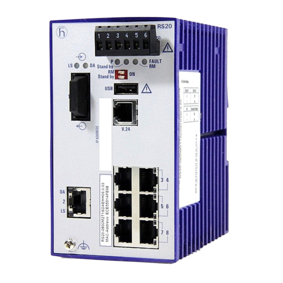
Page 24: Number Of Ports And Media For Rs20
1.1.3 Number of ports and media for RS20-... RS20 FAULT +24V(P1) 0V 0V +24V(P2) FAULT Stand by Stand by V.24 RS20 RS20 FAULT FAULT +24V(P1) 0V 0V +24V(P2) +24V(P1) 0V 0V +24V(P2) FAULT FAULT Stand by Stand by Stand by Stand by V.24 V.24... - Page 25 RS20 FAULT +24V(P1) 0V 0V +24V(P2) FAULT Stand by Stand by V.24 RS20 RS20 FAULT FAULT +24V(P1) 0V 0V +24V(P2) +24V(P1) 0V 0V +24V(P2) FAULT FAULT Stand by Stand by Stand by Stand by V.24 V.24 RS20-0800M2M2...D... RS20-0800T1T1...D... RS20-0800M2T1...D... Figure 2: Device variants with 8 × 10/100 Mbit/s ports (RS20-0800...) 1 to 9 –...
- Page 26 RS20 FAULT +24V(P1) 0V 0V +24V(P2) FAULT Stand by Stand by V.24 RS20 RS20 FAULT FAULT +24V(P1) 0V 0V +24V(P2) +24V(P1) 0V 0V +24V(P2) FAULT FAULT Stand by Stand by Stand by Stand by V.24 V.24 RS20-2400M2M2...D... RS20-2400M2T1...D... RS20-2400T1T1...D... Figure 4: Device variants with 24× 10/100 Mbit/s ports (RS20-2400...) 1 to 9 –...
-
Page 27: Number Of Ports And Media For Rs30
9 – Port 1 + Port 2, Connection as required: MM: Multimode FX, DSC, 100 Mbit/s NN: Multimode FX, ST, 100 Mbit/s VV: Single-mode FX, DSC, 100 Mbit/s UU: Single-mode FX, ST, 100 Mbit/s LL: Single-mode long haul FX, DSC, 100 Mbit/s GG: Single-mode long haul+ FX, DSC, 100 Mbit/s, 200 km 10 –... - Page 28 RS30 FAULT +24V(P1) 0V 0V +24V(P2) FAULT Stand by Stand by V.24 RS30 RS30 FAULT FAULT +24V(P1) 0V 0V +24V(P2) +24V(P1) 0V 0V +24V(P2) FAULT FAULT Stand by Stand by Stand by Stand by V.24 V.24 RS30-1602T1T1...D... RS30-1602O6O6...D... RS30-1602O6T1...D... Figure 7: Device variants with 2× 1000 Mbit/s ports and 16 × 10/100 Mbit/s ports (RS23-1602...) 1 to 9 –...
- Page 29 RS30 RS30 RS30 FAULT FAULT FAULT +24V(P1) 0V 0V +24V(P2) +24V(P1) 0V 0V +24V(P2) +24V(P1) 0V 0V +24V(P2) FAULT FAULT FAULT Stand by Stand by Stand by Stand by Stand by Stand by V.24 V.24 V.24 RS30-2402OOZZ...D... RS30-1602OOZZ...D... RS30-0802OOZZ...D... Figure 9: Device variants with 4 uplink ports 1 to 6 –...
-
Page 30: Number Of Ports And Media For Rs40
1.1.5 Number of ports and media for RS40-... RS40 FAULT +24V(P1) 0V 0V +24V(P2) FAULT Stand by Stand by V.24 FAULT RS40 +24V(P1) 0V 0V +24V(P2) FAULT Stand by Stand by V.24 RS40-0009CCCCED... RS40-0009CCCCSD... RS40-0009CCCCTD... Figure 10: Device variants with 9 × 1000 Mbit/s ports (RS40-0009...) 1 to 5 and 8 to 9 –... -
Page 31: Device Variants With Poe (Optional)
Device variants with PoE (optional) 1.2.1 Number of ports and media for devices with PoE FAULT RS22 +48V(P1) 0V 0V +48V(P2) FAULT Stand by Stand by V.24 RS22-1700MMM2...P... Figure 11: RS22 device variants with PoE (for example: RS22-1700MMM2...P...) 1 to 5 and 7 to 9 – see figure 5 6 –... - Page 32 RS32 FAULT +48V(P1) 0V 0V +48V(P2) FAULT Stand by Stand by V.24 RS32-0802OOZZ...P... Figure 12: RS32 device variants 4 uplink ports (for example: RS32-0802OOZZ...P...) 1 to 5 and 7 to 9 – see figure 9 6 – Ports as per 10/100BASE-T(X) (RJ45 connectors, the PoE-capable ports 7 to 10 are marked accordingly) Device variants RS22-...
-
Page 33: Poe Power Units
1.2.2 PoE power units The following PoE power units are available for supplying the devices with PoE voltage: RPS90/48V LV: Low voltage PoE power supply unit Input voltage range: 24 V DC to 48 V DC Output power at up to +60 °C: 90 W Output power at +60 °C to +70 °C: 60 W ... -
Page 34: 10/100 Mbit/S Twisted Pair Port
Delivery state: Autonegotiation enabled The port housing is electrically connected to the front panel. The pin assignments comply with MDI-X. Function BI_DB+ BI_DB− BI_DA+ BI_DD+ BI_DD− BI_DA− BI_DC+ BI_DC− Table 7: Pin assignments of the 10/100/1000 Mbit/s twisted pair port in 1000 Mbit/s mode, RJ45 socket, MDI-X mode 1.3.2 10/100 Mbit/s twisted pair port... -
Page 35: 1000-Mbit/S F/O Port
This port supports: Autonegotiation Autopolarity Autocrossing (if autonegotiation is activated) 100 Mbit/s half duplex, 100 Mbit/s full duplex, 10 Mbit/s half duplex, 10 Mbit/s full duplex. Power over ETHERNET (PoE, at the last four ports of the device) Delivery state: Autonegotiation enabled The socket housing is electrically connected with the front panel. -
Page 36: 100 Mbit/S F/O Port
1.3.5 100 Mbit/s F/O port In device variants RS20 and RS22, these ports are DSC connectors or ST connectors. In device variants RS30, RS32 and RS40, these ports are SFP slots. The 100 Mbit/s F/O port offers you the ability to connect network components according to the IEEE 802.3 100BASE-FX standard. -
Page 37: Display Elements
Delivery state: 100 Mbit/s full duplex when using a Fast Ethernet SFP transceiver 1000 Mbit/s full duplex when using a Gigabit Ethernet SFP transceiver Display elements After the supply voltage is set up, the software starts and initializes itself. Afterwards, the device performs a self-test. -
Page 38: Management Interfaces
RM and Stand-by - display saving processes of the AutoConfiguration Adapter (ACA) Flashing alternately Error during saving process. LEDs flash synchronously, two Loading configuration from the ACA. times a second LEDs flash synchronously, Saving the configuration in the ACA. once a second Port status ... -
Page 39: Interface (External Management)
Figure Function VCC (VBus) − Data + Data Ground (GND) Table 11: Pin assignment of the USB interface 1.5.2 V.24 interface (external management) The V.24 interface is an RJ11 socket. At the V.24 connection, a serial interface is provided for the local connection of an external management station (VT100 terminal or PC with corresponding terminal emulation) or an AutoConfiguration Adapter ACA 11. -
Page 40: Installation
Installation The devices have been developed for practical application in a harsh industrial environment. On delivery, the device is ready for operation. To install and configure the device, please complete the following steps: Checking the package contents Installing and grounding the device ... -
Page 41: Snapping A Unit Onto The Din Rail
Only when using the PoE power supply unit RPS90/48V HV: WARNING ELECTRIC SHOCK Install this device only in a switch cabinet or in a restricted access location, to which maintenance staff have exclusive access. Install the device at ambient temperatures greater than 113 °F (45 °C) in “restricted access locations”... -
Page 42: Din Rail Mounting On Ships (Rs30-0802
Note: The overall shield of a connected shielded twisted pair cable is connected to the ground connector on the front panel as a conductor. 2.2.2 DIN rail mounting on ships (RS30-0802...) When you are mounting your RS30-0802... Open Rail device on a DIN rail on ships and in similar applications, the Open Rail Mounting Kit available as an accessory can be used to avoid excessive resonance. -
Page 43: Mounting On A Vertical Flat Surface
2.2.3 Mounting on a vertical flat surface Applies to the device variants RS22 and RS32: You have the option of attaching the device to a vertical flat surface. You need a wall mounting plate for this, which you can purchase as an accessory. See “Accessories”... -
Page 44: Installing An Sfp Transceiver (Optional)
Installing an SFP transceiver (optional) Exclusively use SFP transceivers by Hirschmann that are suitable for this device. See “Accessories” on page 67. Proceed as follows: Remove the protection cap from the SFP transceiver. Push the SFP transceiver with the lock closed into the slot until it latches Adjust DIP switch settings The 2-pin DIP switch on the front panel of the device gives you the following options:... -
Page 45: Wiring The Terminal Blocks
Wiring the terminal blocks WARNING ELECTRIC SHOCK Connect only a supply voltage that corresponds to the type plate of your device. Never insert sharp objects (small screwdrivers, wires, etc.) into the connection terminals for electric conductors, and do not touch the terminals. Observe the maximum values for contact load of the signal contact. -
Page 46: Rs22/Rs32: Supply Voltage And Signal Contact
With a non-redundant supply of the supply voltage, the device reports the loss of a supply voltage. You can prevent this message by changing the configuration in the Management. Signal contact for RS20/RS30/RS40 The signal contact ("FAULT", pin assignment of terminal block figure 18) is used to monitor the device function, and thus supports remote diagnostics. - Page 47 The power supply unit and the devices with PoE ports form a “limited power source” according to IEC 60950-1. The external PoE power supply unit must be able to provide the power for the connected PDs (Power Devices) and for the Switch. RPS90/48V LV: Connecting the input voltage ...
- Page 48 Figure Assignment Supply voltage range Protective conductor High voltage input voltage: 60 V DC to 250 V DC Minus terminal of the supply voltage Plus terminal of the supply voltage = external fuse for supply voltages > 125 V DC Table 14: Connecting the high-voltage supply voltage at PoE power unit RPS90/48V HV (DC voltage) ...
- Page 49 Connect the PoE voltage to the 6-pin terminal block for the device included in the delivery. Make sure the following requirements are met: Supply line length < 0,5 m. FAULT +48V(P1) 0V 0V +48V(P2) Figure 19: Connecting the PoE voltage at the 6-pin terminal block of the RS22/RS32 devices RS22/RS32 signal contact ...
-
Page 50: Mounting A Terminal Block
Mounting a terminal block Mount the terminal block for the voltage supply and signal contact on the front of the device using the snap lock. Make sure that the latching mechanism engages. Connecting the ferrite Note: For Power over Ethernet devices with 16 or more ports (RS22-16..., RS22-17..., RS22-24... -
Page 51: Connecting Data Cables
Connecting data cables In general, adhere to the following recommendations for data cable connections in environments with high electrical interference levels: Keep the length of the data cables as short as possible. Use optical data cables for the data transmission between the buildings. ... -
Page 52: Making Basic Settings
Making basic settings WARNING UNINTENTIONAL OPERATION IN DEVICE Install and maintain a process that assigns a unique IP address to every device in the network. Failure to follow these instructions can result in death, serious injury, or equipment damage. The IP parameters must be entered when the device is installed for the first time. -
Page 53: Monitoring The Ambient Air Temperature
Monitoring the ambient air temperature Only operate the device up to the specified maximum ambient air temperature. See “General technical data” on page 57. The ambient air temperature is the temperature of the air at a distance of 5 cm from the device. It depends on the installation conditions of the device, e.g. -
Page 54: Maintenance And Service
Maintenance and service When designing this device, Hirschmann largely avoided using wear parts. The parts subject to wear and tear are dimensioned to last longer than the lifetime of the product when it is operated normally. Operate this device according to the specifications. ... -
Page 55: Disassembly
Disassembly Removing the device WARNING ELECTRIC SHOCK Disconnect the grounding only after disconnecting all other cables. Failure to follow these instructions can result in death, serious injury, or equipment damage. RS20/RS30/RS40 RS22/RS32 Proceed as follows: Disconnect the data cables. ... -
Page 56: Removing An Sfp Transceiver (Optional)
Removing an SFP transceiver (optional) Proceed as follows: Pull the SFP transceiver out of the slot via the open locking mechanism. Close the SFP transceiver with the protection cap. Installation RS20/22/30/32/40 Release 04 02/2015... -
Page 57: Technical Data
Technical Data General technical data Dimensions RS20-0400... 1.85 in. × 5.16 in. × 4.37 in. W × H × D RS20-08..., RS20-09..., RS30-0802 (47 mm × 131 mm × 111 mm) RS20-16..., RS20-17..., RS30-1602 2.91 in. × 5.16 in. × 4.37 in. RS20-24..., RS20-25..., RS30-2402 (74 mm ×... - Page 58 Power supply Nominal voltage AC 48 V RS22-..., RS32-... Max. Voltage range AC 47 V ... 52 V (incl. max. tolerances) Connection type 6-pin terminal block with snap lock Power failure bridging > 10 ms Back-up fuse Nominal rating: 3,5 A Characteristic: slow blow Peak inrush current...
- Page 59 Environment Storage temperature Standard: −40 °F ... +158 °F (ambient air temperature) (−40 °C ... +70 °C ) Extended −40 °F ... +185 °F (−40 °C ... +85 °C ) Humidity 10 % ... 95 % (non-condensing) Air pressure Up to 2000 m (795 hPa), higher altitudes on request Minimum clearance around the Top and bottom device side: 3.94 in...
- Page 60 Dimension drawings inch 4.17 0.55 1.81 Figure 21: Dimensions of device variants RS20-04... with operating temperature characteristic value S, T and E inch 2.84 4.17 0.55 Figure 22: Dimensions of device variants - RS20-08... and RS20-09...with operating temperature characteristic value S, T and E - RS30-08...
- Page 61 inch 4.33 4.17 0.55 Figure 23: Dimensions of device variants - RS20-16... , RS20-17... and RS20-24...with operating temperature characteristic value S, T and E - RS30-16... and RS30-24... with operating temperature characteristic value S, T and E - RS40-09... with operating temperature characteristic value T and E 3.55 4.53 0.47...
- Page 62 4.53 4.73 0.47 Figure 25: Dimensions of device variants RS22.../RS32... with 16 to 26 ports with operating temperature characteristic value S, T and E 7,05 2.36 4.53 0.28 Figure 26: Dimensions of RPS90/48V LV and RPS90/48V HV PoE power units EMC and immunity ...
- Page 63 EMC compliance – IEC/EN 61000-6-2:2005 EMI TYPE tests, test acc. to: IEC/EN 61000-4-3 Electromagnetic field 80 MHz ... 3000 MHz 10 V/m 20 V/m 20 V/m IEC/EN 61000-4-4 Fast transients (burst) Power line 2 kV 4 kV 4 kV Data line 1 kV 4 kV 4 kV...
- Page 64 Product Wave Fiber System Example Fiber code length attenuatio of optical attenuatio Dispersion M-SFP-... fiber line length -SX/LC... MM 850 nm 50/125 µm 0-7.5 dB 0-550 m 3.0 dB/km 400 MHz×km -SX/LC... MM 850 nm 62.5/125 µm 0-7.5 dB 0-275 m 3.2 dB/km 200 MHz×km -MX/LC...
- Page 65 Product Wave Fiber System Example Fiber BLP/ code length attenuatio of optical attenuation dispersion M-FAST- fiber line SFP-... length -MM/LC... MM 1310 nm 50/125 µm 0-8 dB 0-5 km 1.0 dB/km 800 MHz×km -MM/LC... MM 1310 nm 62.5/125 µm 0-11 dB 0-4 km 1.0 dB/km 500 MHz×km...
- Page 66 Device name Device model Maximum Power output power consumption RS20-1600... RS22-1600... 1xFX port, 1xTX port 10.6 W 36.2 Btu (IT)/h RS20-1600... RS22-1600... 2xFX port 11.8 W 40.3 Btu (IT)/h RS20-2400-... RS22-2400-... 2xTX port 12.1 W 41.3 Btu (IT)/h RS20-2400-... RS22-2400-... 1xFX port, 1xTX port 13.3 W 45.4 Btu (IT)/h...
- Page 67 Device name Device model Maximum Power output power consumption RS32-1602-... 2xTX port 78.6 W 58.1 Btu (IT)/h RS32-1602-... 1xFX port, 1xTX port 78.3 W 57.1 Btu (IT)/h RS32-1602-... 2xFX port 78.0 W 56.1 Btu (IT)/h RS32-2402-... 2xTX port 81.3 W 67.3 Btu (IT)/h RS32-2402-...
- Page 68 Gigabit Ethernet SFP transceiver Order number M-SFP-TX/RJ45 943 977-001 Note the following for the M-SFP-TX/RJ45 transceiver: Usable with: - HiOS as of software version 03.0.00 - Classic Switch software, as of software version 04.1.00. - HiSecOS as of software version 01.2.00 Do not use with the following devices: - SPIDER II - MSP/MSM...
- Page 69 Fast Ethernet SFP transceiver Order number M-FAST SFP-SM+/LC 943 867-001 M-FAST SFP-SM+/LC EEC 943 945-501 M-FAST SFP-LH/LC 943 868-001 M-FAST SFP-LH/LC EEC 943 945-501 Special accessories for the RS22/RS32 device variants: Order number Wall mounting plate in DIN rail design, width 4.72 in. (120 mm) 943 971-001 Wall mounting plate for DIN rail mounting, width 3.54 in.
- Page 70 Name IEEE 802.1 D Media access control (MAC) bridges (includes IEEE 802.1p Priority and Dynamic Multicast Filtering, GARP, GMRP) IEEE 802.1Q Virtual LANs (VLANs, MRP, Spanning Tree) IEEE 802.1 Q Virtual Bridged Local Area Networks (VLAN Tagging, GVRP) IEEE 802.1w Rapid Reconfiguration IEEE 802.3 Ethernet...
-
Page 71: A Further Support
Contact our support at https://hirschmann-support.belden.eu.com Contact us in the EMEA region at Tel.: +49 (0)1805 14-1538 Email: hac.support@belden.com in the America region at Tel.: +1 (717) 217-2270 Email: inet-support.us@belden.com in the Asia-Pacific region at ... - Page 72 Installation RS20/22/30/32/40 Release 04 02/2015...
- Page 73 Installation RS20/22/30/32/40 Release 04 02/2015...
Need help?
Do you have a question about the Hirschmann RS20 Series and is the answer not in the manual?
Questions and answers