Belden Hirschmann OCTOPUS 8TX-EEC Installation Manual
Ip65/67 switch
Hide thumbs
Also See for Hirschmann OCTOPUS 8TX-EEC:
- Description and operating instructions (9 pages) ,
- User manual (66 pages)

Related Manuals for Belden Hirschmann OCTOPUS 8TX-EEC


Summary of Contents for Belden Hirschmann OCTOPUS 8TX-EEC
- Page 1 User Manual Installation IP65/67 Switch OCTOPUS 8TX-EEC OCTOPUS 8TX PoE-EEC OCTOPUS 8TX-EEC-M Installation OCTOPUS 8TX-EEC Technical support Release 07 01/2021 https://hirschmann-support.belden.com...
- Page 2 The naming of copyrighted trademarks in this manual, even when not specially indicated, should not be taken to mean that these names may be considered as free in the sense of the trademark and tradename protection law and hence that they may be freely used by anyone. ©...
-
Page 3: Table Of Contents
Contents Safety instructions About this Manual Legend Description General device description Device view 1.2.1 OCTOPUS 8TX-EEC 1.2.2 OCTOPUS 8TX PoE-EEC 1.2.3 OCTOPUS 8TX-EEC-M Power supply Ethernet ports 1.4.1 10/100 Mbit/s twisted pair port 1.4.2 10/100 Mbit/s PoE port 1.4.3 Pin assignment OCTOPUS 8TX-EEC and OCTOPUS 8TX-EEC-M 1.4.4 Pin assignment OCTOPUS 8TX PoE-EEC Display elements... - Page 4 2.3.3 Pin assignment OCTOPUS 8TX PoE-EEC 2.3.4 Pin assignment OCTOPUS 8TX-EEC-M Operating the device Connecting data cables Configuration (optional) 2.6.1 Configuration readout Making basic settings First login (Password change) Monitoring the ambient air temperature Maintenance and service Disassembly Technical data General technical data Dimension drawings EMC and immunity...
-
Page 5: Safety Instructions
Safety instructions WARNING UNCONTROLLED MACHINE ACTIONS To avoid uncontrolled machine actions caused by data loss, configure all the data transmission devices individually. Before you start any machine which is controlled via data transmission, be sure to complete the configuration of all data transmission devices. Failure to follow these instructions can result in death, serious injury, or equipment damage. - Page 6 Installation site requirements When you are selecting the installation location, make sure you observe the climatic threshold values specified in the technical data. Operate the device at the specified ambient temperature (temperature of the ambient air at a distance of 2 in (5 cm) from the device) and at the specified relative humidity exclusively.
- Page 7 National and international safety regulations Verify that the electrical installation meets local or nationally applicable safety regulations. Shielding ground The overall shield of a connected shielded twisted pair cable is connected to the ground connection on the metal housing as a conductor. ...
- Page 8 Requirements for connecting the supply voltage Alternative 3 All of the following requirements are complied with: The power supply complies with the requirements for a safety extra-low voltage (SELV) as per IEC/EN 60950-1. Install a fuse suitable for DC voltage in the plus conductor of the power supply.
- Page 9 E marking The labeled devices comply with the conditions of ECE Directive No. 10: Certified devices must be labeled with the E type approval indicator. The labeled devices comply with the conditions of ECE Directive No. 118: Certified devices must be labeled with the E type approval indicator. OCTOPUS 8TX-EEC devices are suited for installation in vehicles according to the conditions of ECE Regulation No.
- Page 10 Supplier's Declaration of Conformity 47 CFR § 2.1077 Compliance Information OCTOPUS 8TX-EEC U.S. Contact Information Belden – St. Louis 1 N. Brentwood Blvd. 15th Floor St. Louis, Missouri 63105, United States Phone: 314.854.8000 This device complies with part 15 of the FCC Rules. Operation is subject...
-
Page 11: About This Manual
About this Manual The “Installation” user manual contains a device description, safety instructions, a description of the display, and the other information that you need to install the device. Documentation mentioned in the “User Manual Installation” that is not supplied with your device as a printout can be found as PDF files for downloading on the Internet at: https://www.doc.hirschmann.com Installation OCTOPUS 8TX-EEC... -
Page 12: Legend
The symbols used in this manual have the following meanings: Listing Work step Subheading Installation OCTOPUS 8TX-EEC Release 07 01/2021... -
Page 13: Description
Description General device description The device is designed for the special requirements of industrial automation. The device meets the relevant industry standards, provides very high operational reliability, even under extreme conditions, and also long-term reliability and flexibility. The device allows you to set up switched Industrial Ethernet networks according to standard IEEE 802.3. -
Page 14: Device View
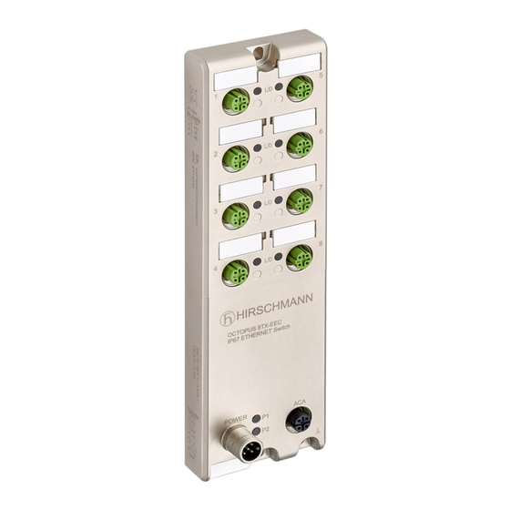
Device view 1.2.1 OCTOPUS 8TX-EEC POWER Item Characteristic Slot hole for mounting on a flat surface 8 × Indicator plate 8 × 4-pin, “D”-coded M12 socket for 10/100 Mbit/s twisted pair connections 8 × LED display elements for port status LED display element for device status M12 interface for the connection of ACA21-M12 (EEC) and ACA22-M12 (EEC) Ground connection... -
Page 15: Octopus 8Tx Poe-Eec
1.2.2 OCTOPUS 8TX PoE-EEC POWER Item Characteristic Slot hole for mounting on a flat surface 8 × Indicator plate 7 × 4-pin, “D”-coded M12 socket for 10/100 Mbit/s twisted pair connections with PoE support 15 × LED display elements for port status PoE status LED display element for device status M12 interface for the connection of ACA21-M12 (EEC) and ACA22-M12 (EEC) - Page 16 The device supports Power over Ethernet Plus in accordance with IEEE 802.3at (PoE+) and enables you to supply current to terminal devices such as IP phones via the twisted-pair cable. The Power over Ethernet Plus function is activated both globally and on the PoE-capable ports on delivery.
-
Page 17: Octopus 8Tx-Eec-M
1.2.3 OCTOPUS 8TX-EEC-M POWER ACA22-C Item Characteristic Slot hole for mounting on a flat surface 8 × Indicator plate 8 × 4-pin, “D”-coded M12 socket for 10/100 Mbit/s twisted pair connections 8 × LED Port status LED display element for device status M12 interface for the connection of ACA22-M12-C (EEC) or a USB adapter cable Ground connection Slot hole for mounting on a flat surface... -
Page 18: Power Supply
Power supply The supply voltage is connected by means of a 5-pin, “A”-coded M12 connector (e. g. ELWIKA 5012 PG7). You will find more information here: “Connecting the power supply and the signal contact lines” on page 32 Ethernet ports You can connect terminal devices and other segments at the ports of the device via twisted pair cables. -
Page 19: Pin Assignment Octopus 8Tx Poe-Eec
This port supports: Autonegotiation Autopolarity Autocrossing 100 Mbit/s half-duplex mode, 100 Mbit/s full duplex mode 10 Mbit/s half-duplex mode, 10 Mbit/s full duplex mode Power over Ethernet (PoE/PoE+) Devices are supplied with PoE voltage (54 V DC SELV) using the internal power supply. -
Page 20: Display Elements
Display elements After the supply voltage is set up, the software starts and initializes itself. During this process, various LEDs light up. 1.5.1 Device state These LEDs provide information about conditions which affect the operation of the whole device. Power Figure 1: Display elements device status OCTOPUS 8TX-EEC Display Color...
Need help?
Do you have a question about the Hirschmann OCTOPUS 8TX-EEC and is the answer not in the manual?
Questions and answers