Table of Contents
Advertisement
Quick Links
User Manual
Installation
Unmanaged IP65/67 Switch
OCTOPUS OS20 / OS24
x y
P1 P2
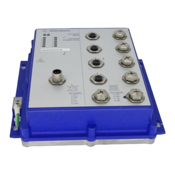
OCTOPUS
OS20
1
6
Unmanaged
2
7
ETHERNET Switch
3
8
4
9
5
10
OS20-001000T5T5TAFUHB
Power
Power
5
3
2
4
1
Pin Function
1
P1+
2
N.C.
3
P-
4
P2+
5
N.C.
OS20–001000T5T5TAFUHB
x y
P1
P2
FAULT
OCTOPUS
OS24
1
6
Unmanaged
2
7
ETHERNET Switch
3
8
P
4
9
5
10
Port 2-5, 7-10
OS24-081000T5T5TFFUHB
Power
1
5
Power
2
4
3
Pin Function
1
P1+
2
3
N.C.
P-
4
5 P2+
OS24–081000T5T5TFFUHB
Installation OCTOPUS OS20/OS24 Unmanaged
Release 10 08/2017
x y
P
OCTOPUS
OS20
1
6
Unmanaged
2
7
ETHERNET Switch
3
8
4
9
5
10
OS20-001000T5T5TNEUHB
Power
Power
4
2
3
1
Pin Function
1
P+
2
N.C.
3
P-
4 N.C.
OS20–001000T5T5TNEUHB
x y
P
FAULT
OCTOPUS
OS24
1
6
Unmanaged
2
7
ETHERNET Switch
3
8
P
4
9
5
10
Port 2-5, 7-10
OS24-081000T5T5TNEUHB
Power
Power
4
2
3
1
Pin Function
1
P+
2
N.C.
3
P-
4 N.C.
OS24–081000T5T5TNEUHB
https://hirschmann-support.belden.eu.com
Technical Support
Advertisement
Table of Contents

Related Manuals for Belden Hirschmann OCTOPUS OS20


Summary of Contents for Belden Hirschmann OCTOPUS OS20
- Page 1 Unmanaged Unmanaged ETHERNET Switch ETHERNET Switch Port 2-5, 7-10 Port 2-5, 7-10 OS24-081000T5T5TFFUHB OS24-081000T5T5TNEUHB Power Power Power Power Pin Function Pin Function N.C. N.C. 4 N.C. 5 P2+ OS24–081000T5T5TFFUHB OS24–081000T5T5TNEUHB Installation OCTOPUS OS20/OS24 Unmanaged Technical Support Release 10 08/2017 https://hirschmann-support.belden.eu.com...
- Page 2 The naming of copyrighted trademarks in this manual, even when not specially indicated, should not be taken to mean that these names may be considered as free in the sense of the trademark and tradename protection law and hence that they may be freely used by anyone. ©...
-
Page 3: Table Of Contents
Contents Safety instructions About this Manual Legend Description General device description Device name and product code Device view Power supply 1.4.1 Supply voltage with the characteristic value A 1.4.2 Supply voltage with the characteristic value F 1.4.3 Supply voltage with the characteristic value N Ethernet ports 1.5.1 10/100 Mbit/s twisted pair port 1.5.2 10/100 Mbit/s PoE port... - Page 4 Connecting data cables Monitoring the ambient air temperature Maintenance and service Technical data Further support Installation OCTOPUS OS20/OS24 Unmanaged Release 10 08/2017...
-
Page 5: Safety Instructions
Safety instructions WARNING UNCONTROLLED MACHINE ACTIONS To avoid uncontrolled machine actions caused by data loss, configure all the data transmission devices individually. Before you start any machine which is controlled via data transmission, be sure to complete the configuration of all data transmission devices. Failure to follow this instruction can result in death, serious injury, or equipment damage. - Page 6 Device casing Only technicians authorized by the manufacturer are permitted to open the casing. Never insert pointed objects (narrow screwdrivers, wires, etc.) into the device or into the connection terminals for electric conductors. Do not touch the connection terminals. ...
- Page 7 Supply voltage The supply voltage is electrically isolated from the housing. Use undamaged parts. Relevant for North America: Only use copper wire/conductors of class 1, 167 °F (75 °C). Applies to devices featuring supply voltage with the characteristic value F: Exclusively connect SELV circuits with the voltage restrictions in accordance with IEC/EN 60950-1 to the supply voltage connections.
- Page 8 E marking The labeled devices comply with the regulations contained in the following European directive(s): Regulation No. 10 of the Economic Commission for Europe of the United Nations (UN/ECE): Devices with an approval are labeled with the E type approval mark. (Relevant for devices with certification type F) CE marking ...
- Page 9 FCC note: This device complies with part 15 of the FCC rules. Operation is subject to the following two conditions: (1) this device may not cause harmful interference; (2) this device must accept any interference received, including interference that may cause undesired operation. Appropriate testing has established that this device fulfills the requirements of a class A digital device in line with part 15 of the FCC regulations.
-
Page 10: About This Manual
About this Manual The “Installation” user manual contains a device description, safety instructions, a description of the display, and the other information that you need to install the device. Installation OCTOPUS OS20/OS24 Unmanaged Release 10 08/2017... -
Page 11: Legend
Legend The symbols used in this manual have the following meanings: Listing Work step Subheading Installation OCTOPUS OS20/OS24 Unmanaged Release 10 08/2017... -
Page 12: Description
Description General device description The OCTOPUS OS20/OS24 Unmanaged devices are designed for the special requirements of industrial automation. They meet the relevant industry standards, provide very high operational reliability, even under extreme conditions, and also long-term reliability and flexibility. The devices allow you to set up switched industrial Ethernet networks that conform to the IEEE 802.3 standard in the line structure. -
Page 13: Device Name And Product Code
The characteristic values stand for specific product properties. You have numerous options of combining the device characteristics. You can determine the possible combinations using the Configurator which is available in the Belden E-Catalog (www.e-catalog.beldensolutions.com) the web page of the device. Item... - Page 14 Item Product Product Value for the characteristic characteristic code Supply voltage Rated voltage range DC See “Power supply” 24 V ... 48 V on page 19. Observe the warning for railway standard EN 50155! See “Devices featuring supply voltage with the characteristic value A” on page Voltage range DC incl.
-
Page 15: Device View
Device view P1 P2 OCTOPUS OS20 Unmanaged ETHERNET Switch OS20-001000T5T5TAFUHB Power Power Pin Function N.C. N.C. OS20-001000T5T5TAFUHB LED display elements Device Status Supply voltage 1 Supply voltage 2 100 Mbit/s ports Connecting the supply voltage Grounding screw Product code LED display elements Port status Installation OCTOPUS OS20/OS24 Unmanaged Release 10 08/2017... - Page 16 OCTOPUS OS20 Unmanaged ETHERNET Switch OS20-001000T5T5TNEUHB Power Power Pin Function N.C. 4 N.C. OS20-001000T5T5TNeUHB LED display elements Device Status Supply voltage 100 Mbit/s ports Connecting the supply voltage Grounding screw Product code LED display elements Port status Installation OCTOPUS OS20/OS24 Unmanaged Release 10 08/2017...
- Page 17 FAULT OCTOPUS OS24 Unmanaged ETHERNET Switch Port 2-5, 7-10 OS24-081000T5T5TFFUHB Power Power Pin Function N.C. 5 P2+ OS24-081000T5T5TFFUHB LED display elements Device Status Supply voltage 1 Supply voltage 2 FAULT Total PoE output Ports 100 Mbit/s ports Ports 100 Mbit/s PoE+ ports 2,3,4,5,7,8,9,10 Connecting the supply voltage Grounding screw...
- Page 18 FAULT OCTOPUS OS24 Unmanaged ETHERNET Switch Port 2-5, 7-10 OS24-081000T5T5TNEUHB Power Power Pin Function N.C. 4 N.C. OS24-081000T5T5TNEUHB LED display elements Device Status Supply voltage FAULT Total PoE output Ports 100 Mbit/s ports Ports 100 Mbit/s PoE+ ports 2,3,4,5,7,8,9,10 Connecting the supply voltage Grounding screw Product code LED display elements...
-
Page 19: Power Supply
Power supply 1.4.1 Supply voltage with the characteristic value A A 5-pin M12 plug is available for the redundant supply to the device. See “Devices featuring supply voltage with the characteristic value A” on page 23. 1.4.2 Supply voltage with the characteristic value F A 5-pin 7/8"... -
Page 20: Ethernet Ports
Ethernet ports You can connect end devices and other segments to the device ports using twisted pair cables or optical fibers (F/O). You find information on pin assignments for making patch cables here: “Pin assignments” on page 21 1.5.1 10/100 Mbit/s twisted pair port This port is designed as an 4-pin M12 socket. -
Page 21: Pin Assignments
The devices are supplied with PoE voltage (53 V DC safety low voltage) via the internal voltage supply. The PoE voltage to the twisted-pair cables is supplied via the wire pairs transmitting the signal (phantom voltage). The total PoE power output is limited to 61.6 W. 1.5.3 Pin assignments M12 4-pin (“D”-coded) -
Page 22: Display Elements
Display elements Device state These LEDs provide information about conditions which affect the operation of the whole device. Display Color Activity Meaning Supply Green Lights up Supply voltage is on voltage 1 None Supply voltage is too low Supply Green Lights up Supply voltage is on... -
Page 23: Installation
Installation The devices have been developed for practical application in a harsh industrial environment. On delivery, the device is ready for operation. Perform the following steps to install and configure the device: Checking the package contents Wiring the connector for the supply voltage ... -
Page 24: Devices Featuring Supply Voltage With The Characteristic Value F
Type and specification of the supply voltage Rated voltage range DC 24 V ... 48 V Voltage range DC incl. maximum tolerances 9.6 V ... 60 V The input voltage is electrically isolated from the housing. You have the option of supplying the supply voltage redundantly, without load distribution. -
Page 25: Devices Featuring Supply Voltage With The Characteristic Value N
Type and specification of the supply voltage Rated voltage range DC 24 V ... 48 V Voltage range DC incl. maximum tolerances 16.8 V ... 60 V The input voltage is electrically isolated from the housing. You have the option of supplying the supply voltage redundantly, without load distribution. -
Page 26: Installing And Grounding The Device
Figure Function + 72 ... 110 V DC N.C. N.C. Not used Not used P− Table 7: Pin assignment of the 4-pin 7/8" connector for connecting the supply voltage Connect the power supply cables. Installing and grounding the device WARNING ELECTRIC SHOCK Applies to devices featuring supply voltage with the characteristic value N:... -
Page 27: Grounding The Device
To protect the exposed uninstalled contacts of the components from dirt, connect the individual system components in a dry and clean working area. When you are selecting the installation location, make sure you observe the climatic threshold values specified in the technical data. Prevent heat from the surroundings from affecting the device. -
Page 28: Connecting The Ferrite
Connecting the ferrite Applies to devices featuring supply voltage with the characteristic value F: To adhere to EMC conformity, you connect the ferrite supplied to the voltage input via the power supply cable. Insert the power supply cable through the ferrite 3 times. ... -
Page 29: Operating The Device
Operating the device When you connect the supply voltage, you start up the device. Connecting data cables You have the option to connect end devices or other segments to the ports of the device via twisted pair cables. Note the following general recommendations for data cable connections in environments with high electrical interference levels: ... - Page 30 Monitoring the ambient air temperature Operate the device below the specified maximum ambient air temperature exclusively. The ambient air temperature is the temperature of the air at a distance of 2 in (5 cm) from the device. It depends on the installation conditions of the device, e.g.
- Page 31 Maintenance and service When designing this device, Hirschmann largely avoided using high-wear parts. The parts subject to wear and tear are dimensioned to last longer than the lifetime of the product when it is operated normally. Operate this device according to the specifications. Relays are subject to natural wear.
- Page 32 Technical data General technical data Dimensions See “Dimension drawings” on page 34. W × H × D Weight 67.02 oz (1900 g) Power supply Redundant power supply Type A Note: Ensure that the externally power unit connected upstream fulfills one of following conditions: ...
- Page 33 Power supply Rated voltage range DC 72 V ... 110 V Type N Voltage range DC incl. maximum 50.4 V ... 138 V tolerances Connection type 7/8" connectors, 4-pin Tightening torque 22 lb-in (2.5 Nm) Power loss buffer > 10 ms No buffering of powered devices (PDs) Overload current protection at input Non-replaceable fuse...
- Page 34 Dimension drawings 183,8 mm 7.24 inch 171,8 mm 6.77 inch Figure 1: Dimensions EMC and immunity EMC interference immunity IEC/EN 61000-4-2 Electrostatic discharge Contact discharge 6 kV Air discharge 8 kV IEC/EN 61000-4-3 Electromagnetic field 80 MHz ... 2700 MHz 20 V/m IEC/EN 61000-4-4 Fast transients (burst)
- Page 35 EMC interference emission German Lloyd Classification + Construction Guidelines VI-7-3 Part 1 Ed.2001 Stability Vibration IEC 60068-2-6 Test FC test level according to IEC 61131-2 Germanischer Lloyd Guidelines for the Performance of Type Tests Part 1 IEC 60870-2-2 table 3 normal installation according to EN 61850-3 EN 61373, Category 1, Class A (broadband noise), installation in acc.
- Page 36 Power consumption/power output Device name and product Maximum power consumption Power output code OS20-001000T5T5TAFUHB 5.8 W 19.8 Btu (IT)/h OS20-001000T5T5TNEUHB 12 W 41 Btu (IT)/h OS24-081000T5T5TFFUHB 80 W 68 Btu (IT)/h OS24-081000T5T5TNEUHB 80 W 68 Btu (IT)/h Scope of delivery ...
- Page 37 Accessories Note: Some products recommended as accessories do not support the entire temperature range specified for the device. They can thus restrict the possible range of usage for the overall system. Special sockets with protection class IP65/67 and an extended temperature range are available on request.
- Page 38 Underlying technical standards Name EN 50121-4 Railway applications - EMC - emitted interference and interference immunity for signal and telecommunication systems EN 50155 Railway applications - Electronic equipment used on rolling stock EN 55032 Electromagnetic compatibility of multimedia equipment – Emission Requirements EN 61000-6-2 Electromagnetic compatibility (EMC) –...
- Page 39 You find the addresses of our partners on the Internet at http://www.hirschmann.com. A list of local telephone numbers and email addresses for technical support directly from Hirschmann is available at https://hirschmann-support.belden.eu.com. This site also includes a free of charge knowledge base and a software download section. Hirschmann Competence Center...
Need help?
Do you have a question about the Hirschmann OCTOPUS OS20 and is the answer not in the manual?
Questions and answers