Table of Contents
Advertisement
Quick Links
User Manual
Installation
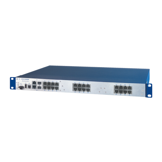
Industrial Ethernet Workgroup Switch
MACH104-PoEP Full Gigabit Family
x y
1
MACH104
FAULT
USB
V.24
FAULT
RM
Sb
P
2
MACH104-16TX-PoEP+2X...
MACH104-16TX-PoEP+2X-R...
MACH104-16TX-PoEP+2X-E...
x y
1
MACH104
FAULT
USB
V.24
FAULT
RM
Sb
P
2
MACH104-16TX-PoEP...
MACH104-16TX-PoEP-R...
MACH104-16TX-PoEP-E...
Installation MACH104-PoEP
Release 10 09/2019
3
5
7
9
11
6
8
10
12
4
3
5
7
9
11
6
8
10
12
4
13
15
17
19
21
14
16
18
20
13
15
17
19
14
16
18
20
https://hirschmann-support.belden.com
22
Technical support
Advertisement
Table of Contents

Related Manuals for Belden Hirschmann MACH104-PoEP Series


Summary of Contents for Belden Hirschmann MACH104-PoEP Series
-
Page 1: User Manual
User Manual Installation Industrial Ethernet Workgroup Switch MACH104-PoEP Full Gigabit Family MACH104 FAULT V.24 FAULT MACH104-16TX-PoEP+2X... MACH104-16TX-PoEP+2X-R... MACH104-16TX-PoEP+2X-E... MACH104 FAULT V.24 FAULT MACH104-16TX-PoEP... MACH104-16TX-PoEP-R... MACH104-16TX-PoEP-E... Installation MACH104-PoEP Technical support Release 10 09/2019 https://hirschmann-support.belden.com... - Page 2 The naming of copyrighted trademarks in this manual, even when not specially indicated, should not be taken to mean that these names may be considered as free in the sense of the trademark and tradename protection law and hence that they may be freely used by anyone. ©...
-
Page 3: Table Of Contents
Contents Safety instructions About this manual Legend Description General device description Device name and product code Device variants available Device views 1.4.1 Front view 1.4.2 Rear view Supply voltage 1.5.1 MACH104-16TX-PoEP... und MACH104-16TX- PoEP+2X... 1.5.2 MACH104-16TX-PoEP-R... und MACH104-16TX- PoEP+2X-R... 1.5.3 MACH104-16TX-PoEP-E... und MACH104-16TX- PoEP+2X-E... - Page 4 Installation Checking the package contents Installing an SFP transceiver (optional) MACH104-16TX-PoEP-E..., MACH104-16TX-PoEP+2X-E...: Wiring and installation of the supply voltage Wiring and installing the signal contact Installing the device and grounding 2.5.1 Selecting the assembly location 2.5.2 Mounting on a flat surface 2.5.3 Mounting in a switch cabinet 2.5.4 Mounting on the wall 2.5.5 Grounding the device...
- Page 5 Underlying technical standards Further support Installation MACH104-PoEP Release 10 09/2019...
-
Page 6: Safety Instructions
Safety instructions WARNING UNCONTROLLED MACHINE ACTIONS To avoid uncontrolled machine actions caused by data loss, configure all the data transmission devices individually. Before you start any machine which is controlled via data transmission, be sure to complete the configuration of all data transmission devices. Failure to follow these instructions can result in death, serious injury, or equipment damage. - Page 7 Certified usage Use the product only for the application cases described in the Hirschmann product information, including this manual. Operate the product only according to the technical specifications. See “Technical data” on page 38. Connect to the product only components suitable for the requirements of the specific application case.
- Page 8 Prerequisites: The supply voltage corresponds to the voltage specified on the type plate of the device. The power supply conforms to overvoltage category I or II. The power supply has an easily accessible disconnecting device (for example a switch or a plug).
- Page 9 Prerequisites: Alternative 3 All of the following requirements are complied with: The power supply complies with the requirements for a safety extra-low voltage (SELV) as per IEC/EN 60950-1. Supply with DC voltage: A fuse suitable for DC voltage is located at both voltage inputs in the plus conductor of the power supply.
- Page 10 Device variant Directive MACH104-16TX-PoEP... 2011/65/EU and 2015/863/EU (RoHS) MACH104-16TX-PoEP+2X... Directive of the European Parliament and of the Council on the MACH104-16TX-PoEP-R... restriction of the use of certain hazardous substances in MACH104-16TX-PoEP+2X-R... electrical and electronic equipment. MACH104-16TX-PoEP-E... 2014/30/EU (EMC) MACH104-16TX-PoEP+2X-E... Directive of the European Parliament and of the Council on the harmonisation of the laws of the Member States relating to electromagnetic compatibility.
- Page 11 Appropriate testing has established that this device fulfills the requirements of a class A digital device in line with part 15 of the FCC regulations. These requirements are designed to provide sufficient protection against interference when the device is being used in a business environment. The device creates and uses high frequencies and can also radiate these frequencies.
-
Page 12: About This Manual
About this manual The “Installation” user manual contains a device description, safety instructions, a description of the display, and the other information that you need to install the device. The following manuals are available as PDF files on the Internet on the Hirschmann product pages (www.hirschmann.com): ... -
Page 13: Legend
Legend The symbols used in this manual have the following meanings: Listing Work step Subheading Installation MACH104-PoEP Release 10 09/2019... -
Page 14: Description
Description General device description The MACH104-PoEP family provides you with a range of device variants. The device is designed for the special requirements of industrial automation. The device meets the relevant industry standards, provides very high operational reliability, even under extreme conditions, and also long-term reliability and flexibility. -
Page 15: Device Name And Product Code
Device name and product code The device name corresponds to the product code. The product code is made up of characteristics with defined positions. The characteristic values stand for specific product properties. Item Product Characteristic Description characteristic value 1 ... 17 Basic properties MACH104- Industrial Ethernet Workgroup Switch with:... -
Page 16: Device Views
Device views 1.4.1 Front view MACH104 FAULT V.24 FAULT LED display Device Status elements Signal contact USB interface V.24 interface Ports 1 ... 4 1000-Mbit/s Combo Ports Ports 5 to 12 1000-Mbit/s Twisted-Pair Ports with PoE+ Ports 13 to 20 1000-Mbit/s Twisted-Pair Ports with PoE+ Ports 21, 22 10-Gbit/s F/O ports... -
Page 17: Rear View
1.4.2 Rear view Non-heating Connecting the supply voltage appliance socket Table 4: Front view of device variants: MACH104-16TX-PoEP... MACH104-16TX-PoEP+2X... Non-heating Connecting the supply voltage appliance socket Supply voltage 2 Non-heating Connecting the supply voltage appliance socket Supply voltage 1 Table 5: Front view of device variants: MACH104-16TX-PoEP-R... -
Page 18: Supply Voltage
Supply voltage Note: Note the safety instructions in “Requirements for connecting electrical wires” on page Note: Observe the information about the voltages to be connected: “Technical data” on page 38 1.5.1 MACH104-16TX-PoEP... und MACH104-16TX- PoEP+2X... For the supply voltage, the following applies: ... -
Page 19: Ethernet Ports
Ethernet ports You can connect end devices and other segments to the device ports using twisted pair cables or optical fibers (F/O). 1.6.1 10/100/1000 Mbit/s twisted pair port This port is an RJ45 socket. The 10/100/1000 Mbit/s twisted pair port allows you to connect network components according to the IEEE 802.3 10BASE-T/100BASE-TX/ 1000BASE-T standard. -
Page 20: 1000 Mbit/S F/O Port
This port supports: Full or half duplex mode Default setting: Full duplex 1.6.3 1000 Mbit/s F/O port This port is an SFP slot. The 1000 Mbit/s F/O port offers you the ability to connect network components according to the IEEE 802.3 100BASE-SX/1000BASE-LX standard. -
Page 21: Combo Ports
The PoE support complies with the following technical standards: Standard Description IEEE 802.3af Brief description Classes max. Powered Device (PD) class 0 (15.4 W) IEEE 802.3at Brief description PoE Plus Classes Max. Powered Device (PD) class 4 (30 W) Table 9: PoE support: technical standards The following applies to PoE ports: ... -
Page 22: Sfp/Xfp Transceiver
1.6.7 SFP/XFP transceiver Figure 1: SFP transceiver and XFP transceiver 1 – Fast Ethernet F/O SFP transceiver 2 – Gigabit Ethernet F/O SFP transceiver 3 – 10-Gigabit Ethernet F/O XFP transceiver SFP is the acronym for Small Form-factor Pluggable which is also commonly known as mini-GBIC (GigaBit Interface Converter). -
Page 23: Device State
1.7.1 Device state FAULT These LEDs provide information about conditions which affect the operation of the whole device. The following table applies to the stated device variants only: MACH104-16TX-PoEP-R... MACH104-16TX-PoEP+2X-R... Display Color Activity Meaning Supply — none Supply voltages 1 and 2 are too low. voltage green lights up... -
Page 24: Port Status
Display Color Activity Meaning ACA memory green Flashing Error in the memory operation operations alternately flashes Saves a configuration file from the storage synchronously medium ACA to the device. 2 × per period flashes Saves a configuration file from the device to synchronously the storage medium ACA. -
Page 25: Management Interfaces
Management interfaces 1.8.1 V.24 interface (external management) The V.24 interface is an RJ11 socket. The V.24 user interface is serial and allows you to connect the following devices directly: External management station (VT100 terminal or PC with appropriate terminal emulation). With this management station, the Command Line Interface (CLI) is available to you. -
Page 26: Signal Contact
Figure Function VCC (VBus) − Data + Data Ground (GND) Table 11: Pin assignment of the USB interface Signal contact The signal contact is a potential-free relay contact. The signal contact is open when the device is not connected to a power supply. The signal contact allows you to control external devices or monitor device functions. -
Page 27: Installation
Installation On delivery, the device is ready for operation. The following procedure has been proven to be successful for the assembly of the device: Checking the package contents MACH104-16TX-PoEP-E..., MACH104-16TX-PoEP+2X-E...: Wiring and installation of the supply voltage Wiring and installing the signal contact ... -
Page 28: Mach104-16Tx-Poep-E
Proceed as follows: Take the SFP transceiver out of the transport packaging (1). Remove the protection cap from the SFP transceiver (2). Push the SFP transceiver with the lock closed into the slot until it latches in (3). MACH104-16TX-PoEP-E..., MACH104-16TX-PoEP+2X-E...: Wiring and installation of the supply voltage... -
Page 29: Wiring And Installing The Signal Contact
Figure Function Protective grounding Minus terminal of the supply voltage Plus terminal of the supply voltage Table 12: 3-pin terminal block pin assignment Remove the terminal connector from the device. Connect the protective conductor with the clamp. Connect the lines for the supply voltage to the + and - terminals. ... -
Page 30: Installing The Device And Grounding
Every time you connect the electrical conductors, make sure that the following requirements are met: The electrical wires are voltage-free. The connected voltage is limited by a current limitation device or a fuse. Observe the electrical threshold values for the signal contact. See “General technical data”... -
Page 31: Mounting In A Switch Cabinet
2.5.3 Mounting in a switch cabinet Note: For more information on sliding/mounting rails and how to install them, please contact your switch cabinet manufacturer. The devices are designed to be mounted in a 19" switch cabinet. Ensure adequate ventilation. If necessary, install an additional fan in the switch cabinet to prevent the device from overheating. -
Page 32: Mounting On The Wall
You obtain the additional brackets as accessories. See “Accessories and order numbers” on page 47. 2.5.4 Mounting on the wall Note: In order to fix the device to a concrete wall choose screws with a thread major diameter of at least 5 mm. ... -
Page 33: Operating The Device
Operating the device WARNING ELECTRIC SHOCK Connect only a supply voltage that corresponds to the type plate of your device. Failure to follow these instructions can result in death, serious injury, or equipment damage. Note: Note the safety instructions in “Requirements for connecting electrical wires”... -
Page 34: Making Basic Settings
Making basic settings Note: Two or more devices configured with the same IP address can cause unpredictable operation of your network. Install and maintain a process that assigns a unique IP address to every device in the network. When you install the device for the first time enter the IP parameters. The device provides the following options for entering the IP parameters during the first installation: ... -
Page 35: Default Settings
Default settings The device looks for the IP address using DHCP Management password: user, password: public (read only) admin, password: private (read and write) V.24 data rate: 9600 Baud Ring redundancy disabled Ethernet ports: link status is not evaluated (signal contact) ... -
Page 36: Maintenance And Service
Maintenance and service When designing this device, Hirschmann largely avoided using high-wear parts. The parts subject to wear and tear are dimensioned to last longer than the lifetime of the product when it is operated normally. Operate this device according to the specifications. See “Technical data”... -
Page 37: Deinstallation
Deinstallation Removing the device Disconnect the data cables. Disable the supply voltage. Disconnect the supply voltage. Remove the terminal connector from the device. To detach the device from the switch cabinet or the wall, remove the screws from the brackets on the device. -
Page 38: Technical Data
Technical data General technical data Dimensions See “Dimension drawings” on page 40. Weight MACH104-16TX-PoEP... 10.14 lb (4.6 kg) MACH104-16TX-PoEP+2X... MACH104-16TX-PoEP-R... 11.46 lb (5.2 kg) MACH104-16TX-PoEP+2X-R... MACH104-16TX-PoEP-E... 9.7 lb (4.4 kg) MACH104-16TX-PoEP+2X-E... Supply voltage MACH104-16TX-PoEP... Rated voltage range MACH104-16TX-PoEP+2X... 100 V AC ... 240 V AC, 50 Hz ... 60 Hz MACH104-16TX-PoEP-R... - Page 39 PoE power Maximum number of Powered 8 × Powered Device (PD) class 4 (30 W) Devices (PDs) 16 × Powered Device (PD) class 0 (15.4 W) Power loss buffer MACH104-16TX-PoEP... > 20 ms MACH104-16TX-PoEP+2X... MACH104-16TX-PoEP-R... MACH104-16TX-PoEP+2X-R... MACH104-16TX-PoEP-E... > 10 ms MACH104-16TX-PoEP+2X-E...
-
Page 40: Dimension Drawings
Dimension drawings 462,6 18.21 0.13 inch 19,3 19,3 0.76 17.48 0.76 EMC and immunity EMC interference immunity IEC/EN 61000-4-2 Electrostatic discharge Contact discharge 6 kV Air discharge 8 kV IEC/EN 61000-4-3 Electromagnetic field 80 MHz ... 3000 MHz max. 20 V/m IEC/EN 61000-4-4 Fast transients (burst) Power line... - Page 41 EMC interference immunity IEC/EN 61000-4-5 Voltage surges This applies to the following device variants only: MACH104-16TX-PoEP-E... MACH104-16TX-PoEP+2X-E... Power line, line / line 0.5 kV Power line, line / ground 1 kV Data line 1 kV This applies to the following device variants only: ...
-
Page 42: Network Range
Network range Note: The line lengths specified for the transceivers apply for the respective fiber data (fiber attenuation and Bandwidth Length Product (BLP)/ Dispersion). 10/100/1000 Mbit/s twisted pair port Length of a twisted pair segment max. 328 ft (100 m) (for Cat5e cable) Table 13: Network range: 10/100/1000 Mbit/s twisted pair port Product code Mode... - Page 43 Product code Mode Wave length Fiber System Example for F/O Fiber /Dispersion M-SFP-... attenuation cable length attenuation -SX/LC... 850 nm 50/125 µm 0 dB ... 7.5 dB 0 mi ... 0.34 mi 3.0 dB/km 400 MHz×km (0 km ... 0.55 km) -SX/LC...
- Page 44 Product code Mode Wave length Fiber System Example for F/O Fiber /Dispersion M-XFP-... attenuation cable length attenuation -SR/LC 850 nm 50/125 µm 0 dB ... 8.1 dB max. 0.041 mi 3.0 dB/km 400 MHz×km (0.066 km) -SR/LC 850 nm 50/125 µm 0 dB ...
- Page 45 Product code Mode Wave length Wave length Fiber System Example for F/O Fiber Dispersion M-SFP-BIDI... attenuation cable length attenuation Type A LH/LC EEC LH 1490 nm 1590 nm 9/125 µm 5 dB ... 24 dB 14.29 mi ... 49.71 mi 0.25 dB/km 19 ps/(nm×km) (23 km ...
-
Page 46: Power Consumption/Power Output
Power consumption/power output MACH104-PoEPdevice Maximum Maximum power consumption power output MACH104-16TX-PoEP... 330 W 300 Btu (IT)/h MACH104-16TX-PoEP+2X... MACH104-16TX-PoEP-R... 340 W 340 Btu (IT)/h MACH104-16TX-PoEP+2X-R... MACH104-16TX-PoEP-E... 300 W 200 Btu (IT)/h MACH104-16TX-PoEP+2X-E... Installation MACH104-PoEP Release 10 09/2019... -
Page 47: Scope Of Delivery, Order Numbers And Accessories
Scope of delivery, order numbers and accessories Scope of delivery Device Scope of delivery MACH104-16TX-PoEP... Device MACH104-16TX-PoEP+2X... General safety instructions Casing feet, stick on 1 × 2-pin terminal block for signal contact 1 × Non-heating appliance cable (Euro model) 2 ×... - Page 48 Name Order number AutoConfiguration AdapterACA21-USB (EEC) 943 271-003 AutoConfiguration AdapterACA11 943 751-001 Terminal cable 943 301-001 2-pin terminal block (50 pieces) 943 845-010 Bracket for fastening the casing 943 943-001 Bracket, long (+ 1.97 in (50 mm)), for fastening the casing (extra) 943 943-101 Network management software Industrial HiVision 943 156-xxx...
- Page 49 Fast Ethernet SFP transceiver Order number M-FAST SFP-TX/RJ45 942 098-001 M-FAST SFP-TX/RJ45 EEC 942 098-002 The following operating conditions apply to twisted pair transceivers: Usable with: - HiOS as of software version 03.0.00 - for PRP ports on RSP devices, as of software version 02.0.01 - for PRP ports on EES devices, as of software version 02.0.02 - Classic switch software as of software version 08.0.00 - HiSecOS as of software version 01.2.00...
- Page 50 Underlying technical standards Name CSA 22.2 No. 60950-1 Information Technology Equipment – Safety – Part 1: General Requirements EN 61000-6-2 Electromagnetic compatibility (EMC) – Part 6-2: Generic standards – Immunity for industrial environments EN 55032 Electromagnetic compatibility of multimedia equipment – Emission Requirements FCC 47 CFR Part 15 Code of Federal Regulations...
-
Page 51: Further Support
A list of local telephone numbers and email addresses for technical support directly from Hirschmann is available at https:// hirschmann-support.belden.com. This site also includes a free of charge knowledge base and a software download section. Hirschmann Competence Center The Hirschmann Competence Center is ahead of its competitors on three counts with its complete range of innovative services: ...
Need help?
Do you have a question about the Hirschmann MACH104-PoEP Series and is the answer not in the manual?
Questions and answers