
Subscribe to Our Youtube Channel
Related Manuals for Belden HIRSCHMANN GREYHOUND GRM Series


Summary of Contents for Belden HIRSCHMANN GREYHOUND GRM Series
- Page 1 User Manual Installation GREYHOUND Switch Hirschmann Switch GREYHOUND GRS1020/1120/1030/1130/GRM Installation GRS1020/1120/1030/1130 Technical support Release 04 01/2020 https://hirschmann-support.belden.com...
- Page 2 The naming of copyrighted trademarks in this manual, even when not specially indicated, should not be taken to mean that these names may be considered as free in the sense of the trademark and tradename protection law and hence that they may be freely used by anyone. ©...
-
Page 3: Table Of Contents
Contents Safety instructions About this Manual Legend Description General device description Device name and product code 1.2.1 Basic device 1.2.2 Media modules Combination options 1.3.1 Basic device 1.3.2 Media modules Device views 1.4.1 Basic device 1.4.2 Port assingment 1.4.3 Media modules Power supply 1.5.1 Supply voltage with characteristic value C 1.5.2 Supply voltage with characteristic value M... - Page 4 Installing and grounding the device Mounting a media module (optional) Installing an SFP transceiver (optional) Connecting the terminal blocks 2.5.1 Supply voltage with characteristic value C 2.5.2 Supply voltage with characteristic value M 2.5.3 Signal contact Operating the device Connecting data cables Filling out the inscription label Making basic settings Default settings...
- Page 5 Scope of delivery Basic device Media modules Accessories General accessories Order numbers Fast Ethernet SFP transceiver Gigabit Ethernet SFP transceiver Bidirectional Gigabit Ethernet SFP transceiver Underlying technical standards Further support Installation GRS1020/1120/1030/1130 Release 04 01/2020...
-
Page 6: Safety Instructions
Safety instructions WARNING UNCONTROLLED MACHINE ACTIONS To avoid uncontrolled machine actions caused by data loss, configure all the data transmission devices individually. Before you start any machine which is controlled via data transmission, be sure to complete the configuration of all data transmission devices. Failure to follow these instructions can result in death, serious injury, or equipment damage. - Page 7 Certified usage Use the product only for the application cases described in the Hirschmann product information, including this manual. Operate the product only according to the technical specifications. See “Technical data” on page 60. Connect to the product only components suitable for the requirements of the specific application case.
- Page 8 Requirements for connecting the supply voltage Before connecting the supply voltage, always verify that the requirements listed are complied with. Prerequisites: All of the following requirements are complied with: The supply voltage corresponds to the voltage specified on the type plate of the device. ...
- Page 9 Prerequisites: Alternative 3 All of the following requirements are complied with: The power supply complies with the requirements for a safety extra-low voltage (SELV) as per IEC/EN 60950-1. Supply with DC voltage: The wire diameter of the power supply cable is at least 1 mm² (North America: AWG16) on the supply voltage input.
- Page 10 Device casing Only technicians authorized by the manufacturer are permitted to open the casing. Keep the ventilation slits free to ensure good air circulation. Make sure there is at least 3.94 in (10 cm) of space in front of the ventilation slits of the casing.
- Page 11 Relevant for use in explosion hazard areas (Hazardous Locations, Class I, Division 2): The relay connections are to be installed and used within their entity parameters as per Control Drawing 000192283DNR. Details see the next two pages. Avertissement - Risque d'explosion - Ne pas débrancher tant que le circuit est sous tension à...
- Page 12 Any GREYHOUND-GRS1xxx device Class I, Division 2 Ordinary location, Groups A, B, C, D non-hazardous area, Hazardous Location non-explosive atmosphere Front view THE USB POWER SUPPLY CONTACTS DEPEND ON THE FOLLOWING PARAMETERS: *) 10 μF 10 μH USB pin 4 USB pin 1 Back view THE RELAY TERMINALS DEPEND ON THE...
- Page 13 SUITABLE FOR USE IN CLASS I DIVISION 2 GROUPS A, B ,C ,D HAZARDOUS LOCATIONS, OR NON-HAZARDOUS LOCATIONS ONLY. For use in HAZARDOUS LOCATIONS only allowed for model numbers which are labelled accordingly. National Electrical Code (NEC), NFPA 70, article 501;CEC, Appendix J, Annex J18. WARNING –...
- Page 14 ESD Guidelines The modules are equipped with electrostatically sensitive components. These can be destroyed, or their life cycles reduced, by the effects of an electrical field or by a charge equalization if the connections are touched. You will find information about electrostatically endangered assemblies in DIN EN 61340-5-1 (2007-08) and DIN EN 61340-5-2 (2007-08).
- Page 15 CE marking The labeled devices comply with the regulations contained in the following European directive(s): Device variant Directive All variants 2011/65/EU and 2015/863/EU (RoHS) Directive of the European Parliament and of the Council on the restriction of the use of certain hazardous substances in electrical and electronic equipment.
- Page 16 47 CFR § 2.1077 Compliance Information GRS1020/1120/1030/1130 GRM20-... U.S. Contact Information Belden – St. Louis 1 N. Brentwood Blvd. 15th Floor St. Louis, Missouri 63105, United States Phone: 314.854.8000 This device complies with part 15 of the FCC rules. Operation is subject to the following two conditions: (1) this device may not cause harmful interference;...
-
Page 17: About This Manual
About this Manual The “Installation” user manual contains a device description, safety instructions, a description of the display, and the other information that you need to install the device. Documentation mentioned in the “User Manual Installation” that is not supplied with your device as a printout can be found as PDF files for downloading on the Internet at: https://www.doc.hirschmann.com Installation GRS1020/1120/1030/1130... -
Page 18: Legend
Legend The symbols used in this manual have the following meanings: Listing Work step Subheading Installation GRS1020/1120/1030/1130 Release 04 01/2020... -
Page 19: Description
Description General device description You can choose from between a wide range of variants. You have the option to set up your device individually based on different criteria: Number of ports Transmission speed Types of connectors Temperature range ... - Page 20 The Network Management Software Industrial HiVision provides you with options for smooth configuration and monitoring. You find further information on the Internet at the Hirschmann product pages: http://www.hirschmann.com/en/QR/INET-Industrial-HiVision The device provides you with a large range of functions, which the manuals for the operating software inform you about.
-
Page 21: Device Name And Product Code
Device name and product code The device name corresponds to the product code. The product code is made up of characteristics with defined positions. The characteristic values stand for specific product properties. 1.2.1 Basic device Item Characteristic Characte- Description ristic value 1 ... - Page 22 Item Characteristic Characte- Description ristic value 16 ... 17 Certificates and You will find detailed information on the certificates and declarations declarations applying to your device in a separate overview. See table 3 on page 23. 18 ... 19 Customer-specific Hirschmann standard version Hardware configuration S...
- Page 23 Application case Certificates and declarations Characteristic value Standard applications EN 60950-1 EN 61131-2 ISA-12.12.01 – Class I, Div. 2 cUL 60950-1 Substation applications IEC 61850-3 IEEE 1613 Navy applications DNV GL Railway applications EN 50121-4 (trackside) Table 3: Assignment: application cases, certificates and declarations, characteristic values a.
-
Page 24: Media Modules
1.2.2 Media modules Item Characteristic Characteristic Description value 1 ... 3 Product GREYHOUND media modules Data rate 10/100 Mbit/s PoE support none (hyphen) – 7 ... 8 Configuration 2 × RJ45 socket for 10/100 Mbit/s Twisted pair Port 1 and port 3 connections 2 ×... -
Page 25: Combination Options
Combination options 1.3.1 Basic device Item 1 ... 3 4 9 ... 12 13 16 ... 17 18 ... 19 20 22 ... 23 24 ... 28 Char Prod Serie Position of Data (hyphen Config Temp Supply Supply Approvals Custome Hardwa Softwar Softwar... -
Page 26: Media Modules
1.3.2 Media modules Item 1 ... 3 7 ... 8 9 ... 10 11 ... 12 13 ... 14 15 16 ... 17 18 ... 19 Charact Device Data (hyphen) Port 1 Port 5 Port 2 Port 6 Temperatur Certificates Customer- Hardware eristic... - Page 27 Item 1 ... 3 7 ... 8 9 ... 10 11 ... 12 13 ... 14 15 16 ... 17 18 ... 19 Charact Device Data (hyphen) Port 1 Port 5 Port 2 Port 6 Temperatur Certificates Customer- Hardware eristic rate support and port...
-
Page 28: Device Views
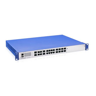
Device views 1.4.1 Basic device 1 2 3 4 USB interface V.24 interface Grounding screw LED display elements 8 × RJ45 socket for 10/100 Mbit/s Twisted pair connections 8 × SFP slot for 100 Mbit/s F/O connections Cover panel Table 5: Front view using example of device variant GRS1020 1 2 3 4 USB interface... - Page 29 Supply voltage connection 1 alternatively, Supply voltage with 2-pin terminal block depending on characteristic value C device variant Supply voltage with 3-pin terminal block characteristic value M Connection for the signal contact Grounding screw Supply voltage connection 2 ...
-
Page 30: Port Assingment
Supply voltage connection 1 alternatively, Supply voltage with 2-pin terminal block depending on characteristic value C device variant Supply voltage with 3-pin terminal block characteristic value M Grounding screw Connection for the signal contact Supply voltage connection 2 alternatively, Supply voltage with ... -
Page 31: Media Modules
1 3 5 7 9 11 11 13 13 15 2 4 6 8 10 12 12 14 14 16 Port Port description 1 ... 16 16 × RJ45 socket for 10/100 Mbit/s Twisted pair connections Table 13: Port assignment: Rear view GRS1120 5 5 7 7 9 9 11 13 15 15 17... - Page 32 Port assignment of the media module variants Port Port description 1, 3 2 × RJ45 socket 5, 7 2 × RJ45 socket 2, 4 2 × RJ45 socket 6, 8 2 × RJ45 socket Table 15: GRM20-TTTTTTTT Port Port description 1, 3 2 ×...
-
Page 33: Power Supply
Default settings Ethernet ports: link status is not evaluated (signal contact) IP address: The device looks for the IP address using DHCP Optical ports: Full duplex TP ports: Autonegotiation Further information on the basic settings of the device can be found in the “Basic Configuration”... -
Page 34: Ethernet Ports
Ethernet ports You can connect end devices and other segments to the device ports using twisted pair cables or optical fibers (F/O). Note: By using media modules, you obtain up to 8 additional Fast Ethernet ports. 1.6.1 Basic device Gigabit combo port ... - Page 35 Delivery state: Autonegotiation activated The port casing is electrically connected to the front panel. The pin assignment corresponds to MDI-X. Function BI_DB+ BI_DB- BI_DA+ BI_DD+ BI_DD- BI_DA- BI_DC+ BI_DC- Table 21: Pin assignments of the 10/100/1000 Mbit/s twisted pair port in 1000 Mbit/s mode, RJ45 socket, MDI-X mode 10/100 Mbit/s twisted pair port ...
-
Page 36: Media Modules
100 Mbit/s F/O port (optional) This port is an SFP slot. The 100 Mbit/s F/O port allows you to connect network components according to the IEEE 802.3 100BASE-FX standard. This port supports: 100 Mbit/s half-duplex mode, 100 Mbit/s full duplex mode Default setting: Full duplex 1.6.2 Media modules... -
Page 37: Display Elements
Function Receive path Receive path Transmission path Transmission path 4, 5, 7, 8 – Table 23: Pin assignment 10/100 Mbit/s twisted pair port, RJ45 socket, MDI-X mode Display elements After the supply voltage is set up, the Software starts and initializes the device. -
Page 38: Port Status
Display Color Activity Meaning Ring Manager – none No redundancy configured green lights up Redundancy exists flashes 1 time Device is reporting an incorrect a period configuration of the RM function yellow lights up No redundancy exists Power Supply voltage –... -
Page 39: Media Module Status
By default, the port status is displayed on the service panel. You have the option of changing between the LED displays using the command line interface (CLI). You require administrator rights for this. To change to the LED display on the port panel, execute the following commands in the CLI: Change to the privileged EXEC mode. -
Page 40: Management Interfaces 1.8.1 V.24 Interface (External Management)
Management interfaces 1.8.1 V.24 interface (external management) A serial interface is provided on the RJ45 socket (V.24 interface) for the local connection of an external management station (VT100 terminal or PC with corresponding terminal emulation). This enables you to set up a connection to the Command Line Interface CLI and to the system monitor. -
Page 41: Usb Interface
1.8.2 USB interface The USB interface allows you to connect the AutoConfiguration Adapter ACA22 storage medium. This is used for saving/loading the configuration data and diagnostic information, and for loading the software. For information about the position on the device see “Device views”... -
Page 42: Signal Contact
Signal contact Figure 1: Signal contact: 2-pin terminal block with screw locking The signal contact is a potential-free relay contact. The signal contact is open when the device is not connected to a power supply. The signal contact allows you to control external devices or monitor device functions. -
Page 43: Installation
Installation The devices have been developed for practical application in a harsh industrial environment. On delivery, the device is ready for operation. Perform the following steps to install and configure the device: Checking the package contents Installing and grounding the device ... - Page 44 CAUTION OVERHEATING OF THE DEVICE Verify that all ventilation slots are clear when installing the device. Avoid touching the device while it is operating. Failure to follow these instructions can result in minor injury or equipment damage. Mounting in a switch cabinet ...
- Page 45 Figure 2: Assembly in a switch cabinet with sliding/mounting rails 1 - device 2 - sliding/mounting rail 3 - 19" switch cabinet Proceed as follows: Assemble the sliding or mounting rails in the 19" switch cabinet as specified by the manufacturer. ...
- Page 46 Mounting on a vertical flat surface WARNING FIRE HAZARD Install the device in a fire enclosure according to EN 60950-1 if you install the device vertically. Failure to follow these instructions can result in death, serious injury, or equipment damage. ...
- Page 47 Grounding the device The device variants have a connection for protective grounding. Ground the device via the ground screw. You find the prescribed tightening torque in chapter: “General technical data” on page 60 Note: This applies to the following device variants only: Supply voltage with characteristic value M The device is grounded via the ground screw and also via the power supply socket.
-
Page 48: Mounting A Media Module (Optional)
Mounting a media module (optional) Hirschmann supplies the media modules in a ready-to-operate state. By using a media module, you obtain up to 8 additional Fast Ethernet ports. You have the option of mounting the media modules while the device is operating. Figure 4: Mounting a media module Proceed as follows: ... -
Page 49: Installing An Sfp Transceiver (Optional)
Installing an SFP transceiver (optional) Prerequisites: Exclusively use Hirschmann SFP transceivers. See “Accessories” on page 74. Figure 5: Installing SFP transceivers: Installation sequence Proceed as follows: Take the SFP transceiver out of the transport packaging (1). Remove the protection cap from the SFP transceiver (2). ... -
Page 50: Connecting The Terminal Blocks
Connecting the terminal blocks WARNING ELECTRIC SHOCK Connect only a supply voltage that corresponds to the type plate of your device. Failure to follow these instructions can result in death, serious injury, or equipment damage. WARNING ELECTRIC SHOCK Never insert pointed objects (narrow screwdrivers, wires, etc.) into the device or into the connection terminals for electric conductors. -
Page 51: Supply Voltage With Characteristic Value M
Type of the voltages Specification of the supply Pin assignment that can be voltage connected DC voltage Rated voltage range Plus terminal of the supply voltage 24 V DC ... 48 V DC Minus terminal of the supply voltage Voltage range incl. maximum tolerances 18 V DC ... -
Page 52: Signal Contact
Type of the voltages Specification of the supply Pin assignment that can be connected voltage DC voltage Rated voltage range Plus terminal of the supply 110 V DC ... 250 V DC voltage Voltage range incl. Minus terminal of the supply maximum tolerances voltage 88 V DC ... -
Page 53: Operating The Device
Operating the device Proceed as follows: Use screws to secure the connectors to the device. You find the prescribed tightening torque in chapter: “General technical data” on page 60 Enable the supply voltage. Connecting data cables Note the following general recommendations for data cable connections in environments with high electrical interference levels: ... -
Page 54: Making Basic Settings
Making basic settings Note: 2 or more devices configured with the same IP address can cause unpredictable operation of your network. Install and maintain a process that assigns a unique IP address to every device in the network. The IP parameters must be entered when the device is installed for the first time. -
Page 55: First Login (Password Change)
Log on to the device again with your new password. Note: If you lost your password, then use the System Monitor to reset the password. For further information see: https://hirschmann-support.belden.com/en/kb/required-password- change-new-procedure-for-first-time-login Installation GRS1020/1120/1030/1130 Release 04 01/2020... -
Page 56: Monitoring The Ambient Air Temperature
Monitoring the ambient air temperature Operate the device below the specified maximum ambient air temperature exclusively. See “General technical data” on page 60. The ambient air temperature is the temperature of the air at a distance of 2 in (5 cm) from the device. It depends on the installation conditions of the device, for example the distance from other devices or other objects, and the output of neighboring devices. -
Page 57: Maintenance And Service
Maintenance and service When designing this device, Hirschmann largely avoided using high-wear parts. The parts subject to wear and tear are dimensioned to last longer than the lifetime of the product when it is operated normally. Operate this device according to the specifications. ... -
Page 58: Disassembly
Disassembly Removing a media module (optional) Figure 8: Demounting a media module Loosen the screws in the front panel of the media module. Open the locking mechanism of the media module by pressing the locking levers outwards (1, 2). ... -
Page 59: Removing An Sfp Transceiver (Optional)
Removing an SFP transceiver (optional) Figure 9: De-installing SFP transceivers: De-installation sequence Proceed as follows: Open the locking mechanism of the SFP transceiver (1). Pull the SFP transceiver out of the slot via the open locking mechanism (2). ... -
Page 60: Technical Data
Technical data General technical data Basic device Dimensions GRS1020 See “Dimension drawings” on page 65. W × H × D GRS1120 GRS1030 GRS1130 Weight GRS1020-16T9 8.16 lb (3.7 kg) Supply voltage with GRS1120-16T9 characteristic value M GRS1030-16T9 8.38 lb (3.8 kg) GRS1130-16T9 GRS1020-8T8Z 7.94 lb (3.6 kg) -
Page 61: Supply Voltage
Media modules Dimensions See “Dimension drawings” on page 65. Weight GRM20-TTTTTTTT 14.48 oz (X = Characteristic (450 g) value M, N, U or V) GRM20-XXXXXXXXS 16.72 oz (520 g) GRM20-XXXXXXXXT 21.45 oz GRM20-XXXXXXXXE (670 g) GRM20-ZZZZZZZZS 20.90 oz Without SFP transceiver GRM20-ZZZZZZZZT (650 g) GRM20-ZZZZZZZZE... -
Page 62: Power Consumption/Power Output
Supply voltage with characteristic value C Rated voltage 24 V DC ... 48 V DC Voltage range incl. maximum 18 V DC ... 60 V DC tolerances Connection type 2-pin terminal block Tightening torque 3 lb-in (0.34 Nm) min. conductor diameter AWG16 (1 mm²) max. -
Page 63: Signal Contact
Signal contact Signal contact Nominal value = 2 A at U = 230 V AC = 2 A at U = 30 V DC = 0.2 A at U = 125 V DC = 0.1 A at U = 250 V DC according to the UL Standards: = 1 A at U = 60 V DC... -
Page 64: Climatic Conditions During Storage
e. If you are using SFP modules without the “EEC” extension, an operating temperature range of +32 °F to +140 °F (0 °C to +60 °C) applies for your device. See “Accessories” on page 74. Applies to device variants with extended temperature range: If more than 4 SFP transceivers are used, the maximum operating temperature is reduced by 2 K per additional SFP transceiver. -
Page 65: Dimension Drawings
Dimension drawings Basic device inch 482,6 465,9 18.3 17.5 10,3 Figure 10: Dimension drawings: basic device Installation GRS1020/1120/1030/1130 Release 04 01/2020... - Page 66 Media modules inch 5.51 128,4 5.05 Figure 11: Dimension drawings: media modules Installation GRS1020/1120/1030/1130 Release 04 01/2020...
-
Page 67: Emc And Immunity
EMC and immunity Note: Use shielded data cables for gigabit transmission via copper cables. Use shielded data cables for all transmission rates to meet the requirements according to EN 50121-4 and marine applications. EMC interference Standard Merchant Navy Railway Substation emission applications applications... - Page 68 EMC interference Standard Merchant Navy Railway Substation immunity applications applications applications (trackside) Electrostatic discharge EN 61000-4-2 Contact discharge ±4 kV ±6 kV ±6 kV ±8 kV IEEE C37.90.3 EN 61000-4-2 Air discharge ±8 kV ±8 kV ±8 kV ±15 kV IEEE C37.90.3 Electromagnetic field EN 61000-4-3...
- Page 69 EMC interference Standard Merchant Navy Railway Substation immunity applications applications applications (trackside) Damped oscillation – DC supply connection EN 61000-4-12 line/ground – – – 2.5 kV IEEE C37.90.1 EN 61000-4-12 line/line – – – 1 kV IEEE C37.90.1 Damped oscillation – data line EN 61000-4-12 line/ground –...
-
Page 70: Network Range
Network range Note: The line lengths specified for the transceivers apply for the respective fiber data (fiber attenuation and Bandwidth Length Product (BLP)/ Dispersion). Product code Mode Wave length Fiber System attenuation Example for F/O Fiber attenuation /Dispersion M-SFP-... cable length -SX/LC... - Page 71 c. Using the bandwidth-length product is inappropriate for expansion calculations. d. With F/O adapter compliant with IEEE 802.3-2002 Clause 38 (single-mode fiber offset-launch mode conditioning patch cord). e. With F/O adapter compliant with IEEE 802.3-2002 Clause 38 (single-mode fiber offset-launch mode conditioning patch cord). Including 2.5 dB system reserve when compliance with the fiber data is observed.
- Page 72 Product code Mode Wave length Fiber System Example for F/O Fiber attenuation BLP/Dispersion M-FAST-SFP-... attenuation cable length -LH/LC... 1550 nm 9/125 µm 10 dB ... 29 dB 29.20 mi ... 64.62 mi 0.25 dB/km 19 ps/(nm×km) (47 km ... 104 km) -LH/LC...
-
Page 73: Scope Of Delivery
Scope of delivery Basic device Number Article 1 × Basic device 1 × 2-pin terminal block for signal contact 1 × 3-pin terminal block for the supply voltage (exclusively for device variants featuring supply voltage with characteristic value M9) 2 × 3-pin terminal block for the supply voltage (exclusively for device variants featuring supply voltage with characteristic value MM) -
Page 74: Accessories
Accessories Note: Note that products recommended as accessories may have characteristics that do not fully correspond to those of the respective product. This may limit their possible usage in the overall system. General accessories General accessories Order number Power Cord, supply voltage cable with EURO connector according to 942 067-001 CEE 7/4 to 3-pin terminal block (4.9 ft (1.5 m)) Power Cord, supply voltage cable with EURO connector according to... -
Page 75: Fast Ethernet Sfp Transceiver
Fast Ethernet SFP transceiver Fast Ethernet SFP transceiver Order number M-FAST SFP-TX/RJ45 942 098-001 M-FAST SFP-TX/RJ45 EEC 942 098-002 The following operating conditions apply to twisted pair transceivers: Usable with: - HiOS as of software version 03.0.00 - for PRP ports on RSP devices, as of software version 02.0.01 - for PRP ports on EES devices, as of software version 02.0.02 - Classic switch software as of software version 08.0.00 - HiSecOS as of software version 01.2.00... - Page 76 Gigabit Ethernet SFP transceiver Order number M-SFP-TX/RJ45 EEC 942 161-001 The following operating conditions apply to twisted pair transceivers: Usable with: - HiOS as of software version 03.0.00 - Classic Switch software, as of software version 04.1.00. - HiSecOS as of software version 01.2.00 Do not use with the following devices: - SPIDER II - MSP/MSM...
-
Page 77: Bidirectional Gigabit Ethernet Sfp Transceiver
Bidirectional Gigabit Ethernet SFP transceiver Bidirectional Gigabit Ethernet SFP transceiver Order number M-SFP-BIDI Type A LX/LC EEC 943 974-001 M-SFP-BIDI Type B LX/LC EEC 943 974-002 M-SFP-BIDI Type A LH/LC EEC 943 975-001 M-SFP-BIDI Type B LH/LC EEC 943 975-002 M-SFP-BIDI Bundle LX/LC EEC (Type A + B) 943 974-101 M-SFP-BIDI Bundle LH/LC EEC (Type A + B) -
Page 78: 10 Underlying Technical Standards
10 Underlying technical standards Name ANSI/ ISA 12.12.01 Nonincendive Electrical Equipment for Use in Class I and II, Division 2, and Class III, Divisions 1 and 2 Hazardous (Classified)Locations CSA C22.2 No. 142 Canadian National Standard(s) – Process Control Equipment – Industrial Products EN 50121-4 Railway applications –... -
Page 79: A Further Support
A list of local telephone numbers and email addresses for technical support directly from Hirschmann is available at https:// hirschmann-support.belden.com. This site also includes a free of charge knowledge base and a software download section. Hirschmann Competence Center The Hirschmann Competence Center is ahead of its competitors on three counts with its complete range of innovative services: ...
Need help?
Do you have a question about the HIRSCHMANN GREYHOUND GRM Series and is the answer not in the manual?
Questions and answers